Table of Contents
Advertisement
Quick Links
Advertisement
Table of Contents

Related Manuals for Tektronix CPS250


Summary of Contents for Tektronix CPS250
- Page 1 User Manual CPS250 Triple Output Power Supply 070-6740-03...
- Page 2 Copyright Tektronix, Inc. 1987. All rights reserved. Tektronix products are covered by U.S. and foreign patents, issued and pending. Information in this publication supercedes that in all previously published material. Specifications and price change privileges reserved. Printed in the U.S.A.
- Page 3 Tektronix, with shipping charges prepaid. Tektronix shall pay for the return of the product to Customer if the shipment is to a location within the country in which the Tektronix service center is located. Customer shall be responsible for paying all shipping charges, duties, taxes, and any other charges for products returned to any other locations.
-
Page 5: Table Of Contents
....... . . Optional Accessories ....... . . CPS250 User Manual... - Page 6 ....Figure 11: Parallel-Tracking Applications ....CPS250 User Manual...
-
Page 7: General Safety Summary
Do Not Operate Without Covers To avoid electric shock or fire hazard, do not operate this product with covers or panels removed. Use Proper Fuse To avoid fire hazard, use only the fuse type and rating specified for this product. CPS250 User Manual... - Page 8 Provide Proper Ventilation To prevent product overheating, provide proper ventilation. Do Not Operate With Suspected Failures If you suspect there is damage to this product, have it inspected by qualified service personnel. CPS250 User Manual...
-
Page 9: Safety Terms And Symbols
CAUTION indicates a hazard to property including the product. Symbols on the Product The following symbols may appear on the product: Double DANGER Protective Ground ATTENTION Insulated High Voltage (Earth) Terminal Refer to Manual CPS250 User Manual... - Page 10 General Safety Summary Certifications and Compliances CSA Certified Power Cords CSA Certification includes the products and power cords appropriate for use in the North America power network. All other power cords supplied are approved for the country of use. CPS250 User Manual...
-
Page 11: Getting Started
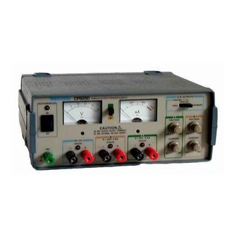
Getting Started The Tektronix CPS250 Triple Output Power Supply is a multifunc- tion bench or portable instrument. The fixed 5 volt output is available for use in transistor-transistor-logic (TTL) applications. Two 0 V to 20 volt, 500 mA, variable outputs meet the needs of most semiconductor test or experimental applications. -
Page 12: Preparing The Power Supply For Use
Getting Started Preparing the Power Supply for Use Check the following items prior to operating the CPS250 Triple Output Power Supply for the first time (see Figure 1 for locations of items 1 through 3): Figure 1: Line Voltage Selectors, Power Input, and Fuse Locations CAUTION. - Page 13 T o prevent damage to the circuit(s) powered by the CPS250 Triple Output Power Supply, check the polarity of the circuit(s) before connecting them to the power supply.
-
Page 14: Front Panel
V and mA meters. Always rotate the adjustment in a clockwise direction for optimum results. 5. A/B Meter Switch. This switch connects the V and mA meters to the A or B output circuit. CPS250 User Manual... - Page 15 14. 5 V 2 A Output. Positive (red) and negative (black) output for fixed 5 volts DC, 2 A maximum. LED lights when OVERLOAD current limit is reached or exceeded. 15. Chassis Ground Connector. The green binding post is connected through the power cord to the power receptacle ground. CPS250 User Manual...
- Page 16 Getting Started CPS250 User Manual...
-
Page 17: Reference
Reference This section of the manual includes examples of how to use the CPS250 Triple Output Power Supply. The number of possible applications is extensive, so only a few examples are given. CAUTION. Heat buildup may occur on the rear-panel heat sink during operation. -
Page 18: Figure 3: Independent Floating Application
To configure the power supply for independent floating, do the following: 1. With the CPS250 Triple Output Power Supply on and the outputs disconnected from loads, set the A and B VOLTAGE controls to the values needed (read on the V meter). Set the A and B CURRENT controls to midrange. - Page 19 GND and the black (–) post of the 5 V, 2 A output. To set up this configuration, proceed as follows: 1. Turn the CPS250 POWER to OFF. Connect the outputs as shown in Figure 4 on page 10.
-
Page 20: Figure 4: Independent Ground-Referenced Applications (A)
Zero to –20 V Zero to 2 A Zero to 0.5 A Zero to 0.5 A Figure 5: Independent Ground-Referenced Applications (B) 1. Turn the CPS250 POWER to OFF. Connect the outputs as shown in Figure 5. CPS250 User Manual... -
Page 21: Figure 6: Connecting The Two 0-20 V Supplies In Series
3. Turn POWER to ON, and observe the V meter in the A and B positions to set the desired voltage. Remember, the total output is the sum of the two readings. 4. Turn tPOWER to OFF, and connect the loads. CPS250 User Manual... -
Page 22: Figure 7: Connections To Provide Fixed +5 V And 0
Figure 7: Connections to Provide Fixed +5 V and 0 to –40 V Figure 8 shows the configuration for three, ground referenced, negative supplies. Load 1 Load 2 Load 3 –5 V Zero to –20 V Zero to –20 V Figure 8: Independent Ground-Referenced Applications (negative output) CPS250 User Manual... -
Page 23: Tracking Mode Applications
A VOLTAGE and A CURRENT controls. For convenience, set the B VOLTAGE and B CURRENT controls fully clockwise to avoid the B supply shutting down. The 5 V fixed supply may be independently grounded or allowed to float. CPS250 User Manual... -
Page 24: Figure 10: Series-Tracking Applications
The parallel output may be floating or ground referenced, but only one terminal (+ or –) may be at ground reference. Those options are shown in Figure 11. The 5 V fixed supply may be independently grounded or allowed to float. CPS250 User Manual... -
Page 25: Figure 11: Parallel-Tracking Applications
Reference Internal connections Load 1 Zero to +20 V 1.0 A Internal connections Load 1 Zero to –20 V 1.0 A Figure 11: Parallel-Tracking Applications CPS250 User Manual... - Page 26 Reference CPS250 User Manual...
-
Page 27: Appendix A: Specifications
Appendix A: Specifications The following tables list the physical, environmental, operational, and electrical characteristics of the CPS250 Triple Output Power Supply: Table 2: Certifications and Compliances EC Declaration of Meets intent of Directive 89/336/EEC for Electromagnetic Conformity – EMC Compatibility. Compliance was demonstrated to the following... - Page 28 0–600 mA 2.5% of full scale Table 6: Electrical Characteristics Line Voltage Range 90 to 110, 108 to 132, 198 to 242, and 216 to 250 VAC at 50–60 Hz Power Consumption 175 VA, 160 W maximum CPS250 User Manual...
-
Page 29: Appendix B: Maintenance
Appendix B: Maintenance This appendix provides information for the basic maintenance of the CPS250 Triple Output Power Supply. Cleaning To clean the power supply, use a soft cloth dampened in a solution of mild detergent and water. Do not spray cleaner directly onto the instrument, since it may leak into the cabinet and cause damage. -
Page 30: Troubleshooting
Appendix B: Maintenance Troubleshooting Electronic maintenance on the CPS250 Triple Output Power Supply must be performed by a trained technician. However, an operator can perform some basic and routine maintenance. The power supply will give some indications of problems to aid the operator. - Page 31 POWER Light ON, but No Output from A or B Supplies with Power Supply connected to Circuit 1. Disconnect the CPS250 outputs from the circuit being tested. Check A and B VOLTAGE and CURRENT controls. 2. If the outputs are good, check the circuit under test for a short or low resistance.
- Page 32 Appendix B: Maintenance CPS250 User Manual...
-
Page 33: Appendix C: Replaceable Parts
Appendix C: Replaceable Parts Replaceable parts may be ordered directly from your authorized Tektronix dealer. Standard Accessories The following items are shipped with the CPS250 Triple Output Power Supply: Table 7: Standard Accessories Accessory Tektronix Part Number Fuse, 3AG, 2A, 250V, SB 159–0023-00... - Page 34 Table 9: Accessory Power Cords Tektronix Part Plug Configuration Normal Usage Number North America 161-0104-00 115 V Europe 161-0104-06 230 V United Kingdom 161-0104-07 230 V Australia 161-0104-05 230 V North America 161-0104-08 230 V Switzerland 161-0167-00 230 V CPS250 User Manual...
Need help?
Do you have a question about the CPS250 and is the answer not in the manual?
Questions and answers