Tektronix PS280 User Manual
Dc power supplies
Hide thumbs
Also See for PS280:
- Service & reference manual (111 pages) ,
- Technical reference (382 pages)
Table of Contents
Advertisement
Quick Links
Download this manual
See also:
Service Reference Manual
Advertisement
Table of Contents

Related Manuals for Tektronix PS280


Summary of Contents for Tektronix PS280
- Page 1 User Manual PS280 & PS283 DC Power Supplies 070-8355-03...
- Page 2 Copyright Tektronix, Inc. 1991. All rights reserved. Tektronix products are covered by U.S. and foreign patents, issued and pending. Information in this publication supercedes that in all previously published material. Specifications and price change privileges reserved. Tektronix, Inc., P.O. Box 1000, Wilsonville, OR 97070–1000...
- Page 3 Tektronix, with shipping charges prepaid. Tektronix shall pay for the return of the product to Customer if the shipment is to a location within the country in which the Tektronix service center is located. Customer shall be responsible for paying all shipping charges, duties, taxes, and any other charges for products returned to any other locations.
-
Page 5: Table Of Contents
Optional Accessories ....... . . PS280 & PS283 User Manual... - Page 6 ..Figure 10: Independent Negative Stacked Application ..Figure 11: Series Tracking Inside the PS280 or PS283 ..Figure 12: Series Tracking Application .
-
Page 7: General Safety Summary
To avoid electric shock or fire hazard, do not operate this product with covers or panels removed. Use Proper Fuse To avoid fire hazard, use only the fuse type and rating specified for this product. PS280 & PS283 User Manual... -
Page 8: Safety Terms And Symbols
If you suspect there is damage to this product, have it inspected by qualified service personnel. Safety Terms and Symbols Terms in This Manual These terms may appear in this manual: WARNING. Warning statements identify conditions or practices that could result in injury or loss of life. PS280 & PS283 User Manual... - Page 9 Certifications and Compliances CSA Certified Power Cords CSA Certification includes the products and power cords appropriate for use in the North America power network. All other power cords supplied are approved for the country of use. PS280 & PS283 User Manual...
- Page 10 General Safety Summary PS280 & PS283 User Manual...
-
Page 11: Getting Started
0 to 4 A for the PS280 at 0 to 30 V, or from 0 to 2 A at 0 to 30 V for the PS283. PS280 & PS283 User Manual... -
Page 12: Preparing The Power Supply For Use
WARNING. To prevent electrical shock, unplug the power cord and disconnect the test leads from the circuit before checking or replacing the fuse. 2. Check that the correct line fuse is installed. The line fuse provides protection if the equipment malfunctions or an overload PS280 & PS283 User Manual... - Page 13 Do not remove the ground lug from the power cord for any reason. 3. Connect the input power cord. Use only the power cords specified for this equipment. Refer to Appendix C: Replaceable Parts on page 33 for power cord part numbers. PS280 & PS283 User Manual...
-
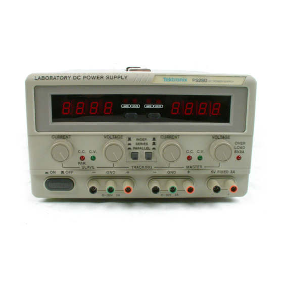
Page 14: Front Panel
Figure 2 shows the front-panel controls, connectors, and indicators with brief descriptions following the figure. 3 4 5 6 Figure 2: PS280 or PS283 Front Panel 1. LED Display. Lights when the instrument is turned on. The numbers indicate the voltage or current produced by the left variable power supply. - Page 15 12. C.V. Indicator. If this is lighted, the left variable power supply is producing a constant voltage. See Figure 3 on page 10 for an illustration of the constant voltage/constant current cross- over point. PS280 & PS283 User Manual...
- Page 16 15. TRACKING Buttons. These buttons select the test mode of the instrument. The PS280 or PS283 features two tracking modes: series and parallel. If both push-button switches are disengaged (out), the two variable power supplies operate independently. If the left switch is pushed in, the instrument operates in series mode.
- Page 17 The red terminal on the right is the positive polarity output terminal. The black terminal on the left is the negative polarity output terminal. 22. The overload indicator lights when the current on the 5 V FIXED power supply becomes too large. PS280 & PS283 User Manual...
-
Page 18: Turning On The Instrument
Getting Started Turning On the Instrument After you have ensured that the PS280 or PS283 is set up for the proper line voltage and has the proper fuse (refer to Preparing the Power Supply for Use on page 2), you are ready to turn it on. -
Page 19: Reference
Reference This section tells how to set the PS280 or PS283 current limit. It also explains the constant voltage/constant current crossover characteris- tic of the instrument. Finally, the section includes procedures for using the instrument in both independent and tracking modes and provides examples of a variety of applications. -
Page 20: Setting The Current Limit
Figure 3: Constant Voltage/Constant Current Crossover Setting the Current Limit Before you begin using the PS280 or PS283 to power a device, you should set its current limit lower than the maximum safe current for the device to be powered. -
Page 21: Test Modes
You are now ready to power your device. Test Modes The two variable power supplies on your PS280 or PS283 can be operated independently of each other, or the slave supply can track the master supply. Below are instructions for operating the instrument in independent modes, followed by instructions for operating the instrument in series or parallel tracking modes. -
Page 22: Figure 4: Independent Floating Application
All outputs are electrically independent. To test a circuit in the independently floating mode, follow these steps: 1. Press the POWER button to apply power to the PS280 or PS283. 2. Rotate the VOLTAGE knob to zero. 3. Determine the polarity of your device. - Page 23 4. Plug one of the test leads into the positive output terminal. 5. Plug the other test lead into the negative output terminal. 6. Press POWER to turn off the PS280 or PS283. 7. Clip the positive test lead to the positive pole of your device.
-
Page 24: Figure 5: Independent Common Ground-Referenced Application
To test a circuit in the independently ground-referenced mode, follow these steps: 1. Turn the POWER off to the PS280 or PS283. 2. Connect the outputs as shown in Figure 5. 3. Set both variable supply VOLTAGE controls to the minimum setting. -
Page 25: Figure 6: Independent Ground-Referenced Split Application
5. Set the AMPS/VOLTS switches for both power supplies to display volts. 6. Turn on the POWER to the PS280 or PS283. The display should read 0 V for both variable power supplies. An external meter connected across the load or load terminals should read –5 V. -
Page 26: Figure 7: Three Ground-Referenced Negative Power Supplies
7. Turn the POWER off to the PS280 or PS283 again. 8. Connect the device or devices to be tested. 9. Turn on the POWER to the PS280 or PS283 again. If necessary, readjust the voltages. Figure 7 shows the configuration for three ground-referenced negative power supplies. -
Page 27: Figure 8: Three Ground-Referenced Positive Power Supplies
0 to 60 V at 0 to 2 A (0 to 1 A for the PS283). Figure 9 on page 18 shows the PS280 or PS283 connected in a stacked manner to produce a variable output of 0 to +60 V ground-referenced. -
Page 28: Figure 9: Independent Positive Stacked Application
7. Turn the POWER off to the PS280 or PS283 again. 8. Connect the device or devices to be tested. 9. Turn on the POWER to the PS280 or PS283 again. If necessary, readjust the voltages. PS280 & PS283 User Manual... -
Page 29: Figure 10: Independent Negative Stacked Application
–60 V output from the variable power supplies and a +5 V output from the FIXED power supply. SLAVE MASTER 5V FIXED 3A Load 2 Load 1 0 to –60 V +5 V Figure 10: Independent Negative Stacked Application PS280 & PS283 User Manual... -
Page 30: Tracking Modes
This connection allows the PS280 or PS283 to produce 0 to 60 V at 0 to 2 A (0 to 1 A for the PS283). -
Page 31: Figure 12: Series Tracking Application
Load 1 0 to +60 V Figure 12: Series Tracking Application 3. Set the PS280 or PS283 to series tracking mode by pressing the left TRACKING button. Make sure that the right TRACKING button is released (out). 4. Set the master AMPS/VOLTS switch to the voltage metering position. - Page 32 9. Turn the POWER off to the PS280 or PS283 again. 10. Connect the device or devices to be tested. 11. Turn on the POWER to the PS280 or PS283 again. Readjust the voltages if necessary. NOTE. The 5 V FIXED supply can be independently grounded or allowed to float.
-
Page 33: Figure 13: Parallel Tracking Inside The Ps280 Or Ps283
1. Turn the POWER off to the PS280 or PS283. 2. Connect the outputs as shown in Figure 14 on page 24. 3. Set the PS280 or PS283 to parallel tracking mode by pressing both tracking buttons. 4. Set the master AMPS/VOLTS switch to the voltage metering position, and set the slave AMPS/VOLTS switch to the current metering position. -
Page 34: Figure 14: Parallel Tracking Application
10. Connect the negative polarity of the device being powered to the negative master terminal. CAUTION. To prevent damage to the PS280 or PS283, do not attempt to obtain output simultaneously from both variable power supplies while in parallel tracking mode. -
Page 35: Appendix A: Specifications
Voltage (5 V) 5.0 0.25 VDC at 3.0 A maximum foldback current limited Voltage (0–30 V) 0–30 constant VDC at 2.0 A constant, maximum (PS280) or 1.0 A constant. maximum (PS283) Line Regulation (5 V) 5 mV Line Regulation (CV) 0.01% +3 mV PS280... - Page 36 Meter Indicators 0–30 VDC (0.5% of reading + 2 digits) 0–2 A (0.5% of reading + 2 digits) Insulation 20 M at DC 500 V (Chassis-to-Terminal) Insulation 30 M at DC 500 V (Chassis-to-AC Cord)) PS280 & PS283 User Manual...
- Page 37 108 to 132 198 to 242 216 to 250, all VAC at 50–60 Hz Power consumption 386 VA, 300 W maximum (PS280) 265 VA, 200 W maximum (PS283) Table 5: Certifications and Compliances EC Declaration of Meets intent of Directive 89/336/EEC for Electromagnetic Conformity –...
- Page 38 Appendix A: Specifications PS280 & PS283 User Manual...
-
Page 39: Appendix B: Maintenance
Appendix B: Maintenance This appendix provides information for the basic maintenance of the PS280 or PS283 Laboratory DC Power Supply. Cleaning To clean the Laboratory DC Power Supply, use a soft cloth dampened in a solution of mild detergent and water. Do not spray cleaner directly onto the instrument, since it may leak into the cabinet and cause damage. -
Page 40: Troubleshooting
Set the voltage control of the voltmeter to midrange. b. Ensure that the range and polarity settings are correct. c. Place the voltmeter jacks in the PS280 or PS283 output terminals. d. Determine if the terminals are producing any output. - Page 41 Disconnect the instrument from the circuit. Check the output terminals with a voltmeter. Are the outputs working? Go to step 10. Go to step 2. 10. Check the circuit you have been testing for a short or low resistance. PS280 & PS283 User Manual...
- Page 42 Appendix B: Maintenance PS280 & PS283 User Manual...
-
Page 43: Appendix C: Replaceable Parts
Accessory Tektronix Part Number Fuse, 5 x 20 mm, 4 A, 250 V, SB 159-0297-00 (PS280: 90 – 132 V operation) Fuse, 5 x 20 mm, 2.5 A, 250 V, SB 159-0226-00 (PS283: 90 – 132 V operation) Test Leads... - Page 44 Table 8: Accessory Power Cords Tektronix Part Plug Configuration Normal Usage Number North America 161-0104-00 115 V Europe 161-0104-06 230 V United Kingdom 161-0104-07 230 V Australia 161-0104-05 230 V North America 161-0104-08 230 V Switzerland 161-0167-00 230 V PS280 & PS283 User Manual...
Need help?
Do you have a question about the PS280 and is the answer not in the manual?
Questions and answers