
Related Manuals for Tektronix PWS2185


Summary of Contents for Tektronix PWS2185
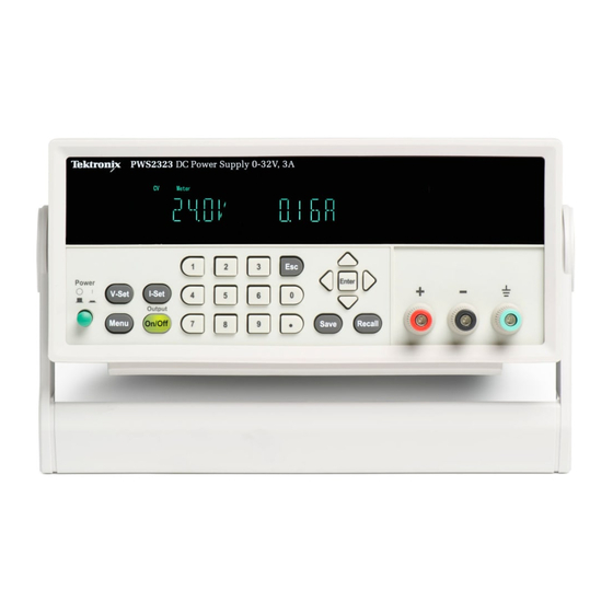
- Page 1 PWS2185, PWS2323, PWS2326, and PWS2721 Linear DC Power Supplies Specifications and Performance Verification Technical Reference *P077048200* 077-0482-00...
-
Page 3: Technical Reference
PWS2185, PWS2323, PWS2326, and PWS2721 Linear DC Power Supplies Specifications and Performance Verification Technical Reference Warning The servicing instructions are for use by qualified personnel only. To avoid personal injury, do not perform any servicing unless you are qualified to do so. Refer to all safety summaries before performing service. - Page 4 Copyright © Tektronix. All rights reserved. Licensed software products are owned by Tektronix or its subsidiaries or suppliers, and are protected by national copyright laws and international treaty provisions. Tektronix products are covered by U.S. and foreign patents, issued and pending. Information in this publication supersedes that in all previously published material.
-
Page 5: Table Of Contents
Table of Contents General Safety Summary ..................Specifications ....................... Performance Verification ..................Test Record ..................... Performance Verification Procedures ............... PWS2000 Series Specifications and Performance Verification... - Page 6 Table of Contents List of Tables Table 1: Specifications ..................... Table 2: Mains power characteristics ................Table 3: Mechanical characteristics ................Table 4: Environment performance................Table 5: Keypad special operations ................Table 6: DC voltage accuracy ..................Table 7: DC voltage readback accuracy ................. Table 8: DC voltage line regulation ................
-
Page 7: General Safety Summary
General Safety Summary General Safety Summary Review the following safety precautions to avoid injury and prevent damage to this product or any products connected to it. To avoid potential hazards, use this product only as specified. Only qualified personnel should perform service procedures. To Avoid Fire or Personal Use proper power cord. - Page 8 General Safety Summary Terms in This Manual These terms may appear in this manual: WARNING. Warning statements identify conditions or practices that could result in injury or loss of life. CAUTION. Caution statements identify conditions or practices that could result in damage to this product or other property.
-
Page 9: Specifications
Specifications that are marked with the symbol are checked in Performance Verification. Table 1: Specifications Parameter PWS2185 PWS2323 PWS2326 PWS2721 Constant voltage The unit may be set to a constant voltage over a range of currents... - Page 10 Specifications Table 1: Specifications (cont.) Parameter PWS2185 PWS2323 PWS2326 PWS2721 Current readback 10 mA resolution, nominal ±(0.1% of reading + 15 mA) Current readback accuracy At 25 °C ±5 °C ±(0.1% + 15 mA) per °C outside the 25 °C ±5 °C standard range...
-
Page 11: Table 2: Mains Power Characteristics
Specifications Table 2: Mains power characteristics Parameter PWS2185 PWS2323 PWS2326 PWS2721 Voltage Two ranges. Bottom-panel switch selectable. 110 V: 110 VAC to 120 VAC 220 V: 220 VAC to 240 VAC Frequency 50/60 Hz Fuse rating, 110 VAC setting: 5 A 110 VAC setting: 5 A 110 VAC setting: 6.3 A... -
Page 12: Table 4: Environment Performance
Specifications Table 4: Environment performance Parameter All models Temperature Operating: +0 °C to +40 °C Nonoperating: -20 °C to 70 °C Humidity Operating: 5% to 95% relative humidity (% RH) at up to 40 °C, noncondensing Nonoperating: 5% to 95% relative humidity (RH) at up to +40 °C, 5% to 60% RH above +40 °C up to +70 C, noncondensing Altitude Operating: 100% capability up to 2,000 meters. -
Page 13: Performance Verification
Performance Verification This section contains performance verification procedures for the specifications marked with the symbol. Additional test equipment is required to complete the verification procedures. (See Table 14 on page 12.) These procedures cover the PW2185, PWS2323, PWS2326, and PWS2721 models. Ignore checks that do not apply to the specific model you are testing. -
Page 14: Test Record
Performance Verification Test Record Model Serial Procedure performed by Date Test Passed Failed Self Test DC voltage accuracy DC voltage readback accuracy DC voltage load regulation DC voltage line regulation DC current accuracy DC current readback accuracy Voltage ripple at 7 MHz Voltage ripple at 20 MHz Current ripple at 20 MHz PWS2000 Series Specifications and Performance Verification... -
Page 15: Table 6: Dc Voltage Accuracy
Performance Verification Table 6: DC voltage accuracy Instrument DUT voltage Test current Measured 0% Test Voltage __________ PWS2185 2.5 A -0.0100 V 0.0100 V __________ PWS2323 1.5 A -0.0100 V 0.0100 V __________ PWS2326 -0.0100 V 0.0100 V __________ 0.75 A -0.0100 V... -
Page 16: Table 7: Dc Voltage Readback Accuracy
Absolute Maximum Instrument DUT voltage Test current voltage readout difference difference 0% Test Voltage ________ ________ ________ 2.5 A 0.01500 V PWS2185 ________ ________ ________ PWS2323 1.5 A 0.01500 V ________ ________ ________ PWS2326 0.01500 V ________ ________ ________ PWS2721 0.75 A... -
Page 17: Table 9: Dc Voltage Load Regulation
Min load Ref load Max load Ref – Min Max – Ref / 0.98 Largest value ________ ________ ________ ________ ________ ________ ________ PWS2185 0.00860 V ________ ________ ________ ________ ________ ________ ________ PWS2323 0.01140 V ________ ________ ________ ________... -
Page 18: Table 11: Dc Current Readback Accuracy
Table 11: DC current readback accuracy Measured Absolute Maximum DVM range Test current current Current readout difference difference 0% Test Current ________ ________ ________ 0.015000 A PWS2185 ________ ________ ________ PWS2323 0.015000 A ________ ________ ________ PWS2326 0.015000 A ________ ________ ________ PWS2721 0.015000 A... -
Page 19: Table 12: Voltage Noise At 20 Mhz
Table 12: Voltage noise at 20 MHz Voltage test Measured Maximum Measured Maximum Instrument load R pk - pk pk - pk ________ ________ PWS2185 4 Ω 2 mV 20 mV ________ ________ 2 mV 20 mV PWS2323 12 Ω ________ ________ PWS2326 6 Ω... -
Page 20: Performance Verification Procedures
Performance Verification Performance Verification Procedures Performance Verification The following conditions must be met before performing these procedures: Conditions 1. The Device Under Test (DUT) and all test equipment must have been operating continuously for 20 minutes in an environment that meets the operating range specifications for temperature and humidity. - Page 21 All resistors should be rated for at least 100 W. Ohms tolerance within 5%. Resistor composition is not critical. To perform the tests as illustrated, both leads of the load resistor require a Banana plug/jack (or equivalent) to connect to the power supply. PWS2185 4 Ω HL10006E5R000JJ PWS2323 12 Ω...
- Page 22 Performance Verification Table 14: Test equipment (cont.) Description Minimum requirements Examples Tektronix part number 14. Coaxial cable 50 Ω BNC, male-to-male 012-0482-00 15. BNC adapter BNC female to banana breakout Pomona Electronics 3073 PWS2000 Series Specifications and Performance Verification...
- Page 23 Performance Verification Self Test This procedure uses internal routines to verify that the DUT functions and passes its internal self tests. No test equipment or hookups are required. Start the self test with these steps: 1. Disconnect all cables from the DUT outputs. 2.
- Page 24 Performance Verification Check DC Voltage Equipment Required Accuracy and DC Voltage (Item 2) AC Power Source (Item 5) High current hook up wire (bold line Readback Accuracy connections) (Item 3) Electronic Load (Item 6) Low current hook up wire (fine line connections) (Item 4) DC Voltmeter 1.
- Page 25 Performance Verification Figure 1: Voltage accuracy and regulation test setup 2. Set the voltmeter as follows: a. Set to measure DC volts. b. Set to auto range. c. Verify that the Analyze mX+b function is disabled, assuring that volts are being read. 3.
- Page 26 Performance Verification 7. Enter the voltmeter reading into the table for checking DC voltage accuracy. (See Table 6 on page 7.) 8. Enter the voltmeter reading into the table for checking DC voltage readback accuracy. (See Table 7 on page 8.) 9.
- Page 27 Verify that the Analyze mX+b function is disabled, assuring that volts are being read. 3. Set the electronic load as follows: a. Set to Constant Current. b. Set to draw the specified test current. Instrument Test current PWS2185 2.5 A 1.5 A PWS2323 PWS2326 3.0 A PWS2721 0.75 A...
- Page 28 Performance Verification 8. Change the AC Power Source output to the maximum voltage specified in the following table. DUT voltage selector switch AC Power Source voltage 132 V 264 V 9. Enter the voltmeter reading into table for checking DC Voltage Line Regulation under the Max column for your product.
- Page 29 Regulation under the minimum load column for your product. (See Table 9 on page 9.) 7. Increase the electronic load to the reference load test current value. Instrument Reference load test current PWS2185 2.5 A PWS2323 1.5 A 0.75 A...
- Page 30 Performance Verification 9. Increase the electronic load to the maximum load test current value. Instrument Reference load test current PWS2185 4.9 A PWS2323 2.94 A PWS2326 1.47 A PWS2721 5.88 A 10. Enter the voltmeter reading into the table for checking DC Voltage Load Regulation under the maximum load column for your product.
- Page 31 Performance Verification Check DC Current and Equipment Required DC Current Readback (Item 2) AC Power Source (Item 5) High current hook up wire (bold line Accuracy connections) (Item 3) Electronic Load (Item 7) High Accuracy 0.05 Ω Resistor (Item 4) DC Voltmeter (Item 8) Current Shunt Resistor Cabling 1.
- Page 32 Performance Verification 2. Set the voltmeter as follows: a. Set to measure DC volts. b. Set to auto range. c. Set to show amps (instead of volts) by multiplying the voltmeter result by 20. Press Analyze button Press mX+B Press mX Set the value to 20 Enable scaling 3.
- Page 33 Performance Verification Check Voltage Noise Equipment Required (20 MHz) (Item 5) High current hook up wire (Item 14) Coaxial cable (BNC M-M) (bold line connections) (Item 9) Load Resistor (Item 15) BNC F-to-Banana (Item 11) Oscilloscope 1. Plug the DUT into your local line power from the mains. 2.
- Page 34 Performance Verification 5. Set the oscilloscope as follows: a. 1 mV/division b. 1 MΩ input resistance c. 20 MHz bandwidth (BW) limit d. AC Coupled e. Auto-trigger 1 ms/div g. Set to measure V and V 6. Set the DUT to the 100% FS output voltage. 7.
- Page 35 Performance Verification Check Current Noise Equipment Required (Item 5) High current hook up wire (Item 11) Oscilloscope (bold line connections) (Item 10) 1 Ω Load Resistor (Item 13) Oscilloscope 10X probe 1. Plug the DUT into your local line power from the mains. 2.
- Page 36 Performance Verification 5. Set the oscilloscope as follows: a. 1 mV/division b. 1 MΩ input resistance c. 20 MHz bandwidth (BW) limit d. AC Coupled e. Auto-trigger 1 ms/div g. Set to measure V and V 6. Set the DUT to the 100% FS output voltage. 7.
Need help?
Do you have a question about the PWS2185 and is the answer not in the manual?
Questions and answers