Advertisement
Quick Links
Advertisement

Related Manuals for Tektronix PS 503A


Summary of Contents for Tektronix PS 503A
- Page 1 COMMI ED O EXCELLENCE PS 503A DUAL POWER SUPPLY INSTRUCTION MANUAL...
-
Page 2: Power Supply
EK RO NIX ® PS 503A ■ DUAL PO WER SUPPLY NSTRUCT ON MANUAL Tektronix, Inc. P.O. Box 500 Beaverton, Oregon 97077 Serial Number _______________________ First Printing SEPT 1974 070-1834-01... - Page 3 PS 503A ABLE OF CON EN S Page SECTION 1 OPERATING INSTRUCTIONS SECTION 2 SPECIFICATION AND PERFORMANCE CHECK WARNING | The remaining portion of this Table of Contents lists servicing instructions that expose personnel to hazardous voltages.- These instructions are for qualified service personnel only.
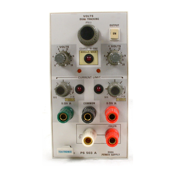
- Page 4 Fig. 1-1. PS 503A Dual Power Supply plug-in module. PS 503A...
- Page 5 0 to 20 Vdc at 1.0 A. Operating in a Installation and Removal standard compartment of a TM 500 Series Power Module, the PS 503A supplies a floating dual 0 to 20 V d c at 400 mA. AUTION ( The supply is designed for conveniently powering urn the power module off before inserting the plug ...
- Page 6 Grounded and Floating Operation OPERA ING CONSIDERA IONS The PS 503A is a + and — 20 V "floating" supply since no internal connections are made to either the chassis or ground. The supply can thus be used as a positive or Overheating negative supply by simply connecting between the com ...
-
Page 7: Current Limit
COMMON, or a negative 0-20 volts between the binding post on the left (green) and COMMON. When the PS 503A is in stalled in the high power compartment of a TM 504 or TM 506 power module that has a high power... - Page 8 2. Press the OUT button to apply power to the PS 503A. Observe that the + and - VOLTS indicator lights come on (the lights will be very dim at low voltages). Single Supply Operation (±20 V Maximum) 1.
- Page 9 3. Remove the ammeter. Connect the load between the Stair-Step Operation common terminal and the + or — terminal. Adjust the + or The PS 503A can be operated to provide a "stair-step" — VOLTS control for the desired output. output characteristic by choosing certain load limits and control settings.
- Page 10 Series-Connected Supplies NO E The outputs of two or more PS 503A ’ s can be con he + and — supplies are internally connected in nected in series as shown in Fig. 1-8 to obtain an output series.
- Page 11 The electrical characteristics are valid only if the are verified by completing the Performance Check in this PS 503A has been calibrated at an ambient temperature manual. Items listed in the Supplemental Information between +20° C and +30° C and is operating at an ambient column are not verified in this manual;...
- Page 12 Specification and Performance Check — PS 503A able 2-1 (cont) Characteristics Performance Requirements Supplemental Information Load Regulation Within 3 mV with a 1 A load change. Within 1 mV with a 400 mA load change. Transient Recover ≤20 µs for a constant voltage to...
- Page 13 Specification and Performance Check — PS 503A able 2-2 ENVIRONMEN AL Performance Requirements Characteristics Supplemental Information Temperature Operating 0°C to +50° C. Storage -40° C to +75° C. Altitude Operating To 15,000 feet. Storage To 50,000 feet. Vibration Operating and With the instruments complete and oper ...
-
Page 14: Performance Check
Specification portion of this section. This procedure checks the electrical characteristics of the PS 503A that appear in the Specification portion of this section. Limits and tolerances given in the Supplemental Information column are provided for user and service est Equipment Required information only, and should not be interpreted as re ... - Page 15 PS 503A is in the out position. 8. Connect all test equipment to a suitable line voltage source. 3. Install the PS 503A in the far right (high power) compartment of the power module. 9. Turn on all test equipment and allow at least twenty minutes for the equipment to warm-up and stabilize.
- Page 16 CURRENT LIMIT control cw just enough to turn them off). d. Move the red patch cord from the PS 503A 0 — 20V red binding post to the PS 503A 0 — 20V green binding post.
- Page 17 PS 503A 0 — 20V red and the COMMON binding post d. Remove the adapter (with load resistor) from the patch cord jacks.
- Page 18 Connect the two 4.99 k Ω , 1% resistors in series (white) binding post. between the PS 503A 0 — 20V green and 0 — 20V red binding post terminals. Do not connect the junction of the two resistors to the COMMON terminal or the chassis.
- Page 19 Specification and Performance Check — PS 503A i. Press and release the PS 503A OUTPUT button to f. Set the PS 503A + and — CURRENT LIMIT controls turn off the power to the PS 503A. fully cw. able 2-5 g.
- Page 20 Preparation Remove the left-hand and right-hand side covers of the PS 503A to gain access to the component side of the circuit boards. Pull the rear end of the side cover outward from the side of the instrument (the cover snaps into place).
- Page 21 1. Adjust 20 Volt Output Voltages e. Adjust — R45, +20 Adj, for a meter reading of +20.2 a. Check — that all controls on the PS 503A front panel volts, ±0.1 volt. See Fig. 3-1 for adjustment location. are fully ccw and the 400 mA MAX indicator light is off...
- Page 22 There special preventive maintenance Module. Connect a digital voltmeter between the +20-volt procedures that apply to the PS 503A. Refer to the power and common output terminals and between the -20-volt module instruction manual for general preventive and common output terminals. Adjust R45, +Adj and maintenance procedures and instructions.
- Page 23 Maximum Racommendad Output or Remarks Loads Input Level Used in conjunction with pin 28A. Disconnect front-panel +VOL S control by moving jumper from F - F to E - E. A by-pass capaci +Volts Resistance tor connected to the CF points may be needed to stop oscil ...
- Page 24 Maximuni Output or Recommended Input Level Loads Remarks +Volts Resistance Programming ~ 500 Ω / Output Volt See pin 28 B remarks -Volts Resistance Programming ~ 500 Ω / See pin 27 B remarks Output Volt — Volts Remote V Programming High Connect by moving Jumper from Input...
- Page 25 View 25 V ac 25 V ac Plug- winding winding Assignments listed tor pins 1A-13A and 1B-13B are available in all power modules; however only those pins marked with an asterisk (*) are used by the PS 503A. •U I...
- Page 26 Apply 9 V from the remote voltage source to the Install a 50 µ F, 25 V d c (minimum rating) capacitor PS 503A. Adjust R45, +Adj and R1 45 — Adj to obtain a 20 V across the remote load. To stop oscillations caused by reading for each supply or the supply being programmed.
- Page 27 Insulate the bare ends of REPACKAGING FOR SHIPMEN the wires. If the Tektronix instrument is to be shipped to a Tektronix Connect the remote load between pin 21 A (4-Volts Service Center for service or repair, attach a tag showing:...
-
Page 28: Current Limit Control
This section of the manual contains a description of the constant-voltage source or a current source — but never circuitry used in the PS 503A Dual Power Supply. In both. Automatic crossover is accomplished by combining dividual descriptions are separated into the following... - Page 29 Circuit Description — PS 503A Fig. 5-1. Simplified block diagram of PS 503A. Load Regulation With no load connected to the output terminals, all of the output current flows through feedback divider R50A- R50B-R42 (approximately 2 mA/V) and back to the minus side of C10.
- Page 30 +5 V Ground-Referenced Supply. The power module supplies +11.5 V through pins 2A and B and 3A and B on If the PS 503A is operated in any compartment of a the plug-in rear connector to pins 1 and 3 of integrated TM 500 Series Power Module except the high power circuit U1.
- Page 31 If a part you have ordered has been replaced with a new or improved part, your local Tektronix, Inc. Field Office or representative will contact you concerning any change in part number.
- Page 32 Replaceable Electrical Parts — PS 503A CROSS INDEX-MFR. CODE NUMBER O MANUFAC URER Mfr. Code Manufacturer Address City, State, Zip 01121 ALLEN-B ADLEY COMPANY 1201 2ND ST EET SOUTH MILWAUKEE, WI 53204 02735 CA CO PO ATION, SOLID STATE DIVISION...
- Page 33 Replaceable Electrical Parts — PS 503A Tektronix Serial/Model No. Ckt No. Part No. Dscont Name & Description Code Mfr Part Number 80009 670-3291-00 B010100 B022064 C T BOA D ASSY:MAIN 670-3291-00 670-3291-01 B022065 CKT BOA D ASSY:MAIN 80009 670-3291-01 283-0081-00 CAP.,FXD,CE...
- Page 34 Replaceable Electrical Parts — PS 503A Tektronix Serial/Model No. Ckt No. Part No. Dscont Name & Description Code Mfr Part Number 151-0342-00 T ANS ISTO : SILICON , PNP 151-0342-00 80009 151-0506-00 C106B2 T ANSISTO : SILICON , SC 03508...
- Page 35 Replaceable Electrical Parts — PS 503A Tektronix Serial/Model No. Ckt No. Part No. Dscont Name & Description Code Mfr Part Number 315-0102-00 ES.,FXD,CMPSN:1K OHM,5%,0.25W 01121 CB1025 01121 315-0152-00 ES.,FXD,CMPSN:1.5K OHM,5%,0.25W CB1525 91637 321-0254-00 ES.,FXD,FILM:4.32K OHM,1%,0.125W MFF1816G43200F 315-0102-00 ES ., FXD , CMPSN : IK OHM,5%,0.25W...
- Page 36 Options — PS 503A OP IONS (No options are available at this time)
- Page 37 Logic symbology is based on ANSI Y32. 14-1973 in terms of positive logic. Logic symbols depict the logic function performed and may differ from the manufacturer's data. Abbreviations are based on ANSI Y1. 1-1972. Other ANSI standards that are used in the preparation of diagrams by Tektronix, Inc. are: Drafting Practices. Y14.15, 1966 Y14.2, 1973...
- Page 38 PS 503A A1 MAIN CIRCUI BOAR! GRID GRID GRID GRID GRID GRID CR185 Q115 CR55 C119 Q120 CR60 C120 Q170 CR66 C138 Q185 CR78 F110 C160 Q190 CR110 C167 Q195 CR145 CR146 CR10 CR148 CR24 CR155 CR45 CR46 CR160 C110...
- Page 39 IN CIRCUI BOARD (SN BO22065-above) GRID GRID GRID GRID GRID GRID GRID R182 R138 VR64 R185 R139 VR117 R142 R187 VR120 R190 R145 VR164 R148 R192 R114 U135 R194 R115 R165 U14S R196 R117 R167 U155 R120 R174 R134 R176 VR20 R135 R178...
- Page 40 Some transistors have voltages present on their cases. Disconnect the power source before replacing parts. The voltages shown on diagram 1 were taken with the PS 503A front panel controls (knob type) fully counterclockwise. The OUTPUT button was in the ON position. No external load was connected to the binding post output terminals.
- Page 41 I8S4--OX PS 5O3A R.&V. P, FEB. IR77...
- Page 42 <J> oweb upply ^4-- FL&V. P; FEB. IR77 bm bowo above...
- Page 43 PS 503A A1 MAIN CIRCUI BOARD (SN BO22064-L GRID GRID GRID GRID GRID GRID GRID CR185 CR48 C119 0115 C120 CR55 CR60 Q120 C138 Q165 CR78 F110 C160 CR110 Q170 C167 R114 CR135 Q185 R115 Q190 CR10 CR145 R117 CR146...
- Page 44 J BO22064 — below) GRID GRID GRID GRID GRID R139 R178 VR30 R142 R180 VR64 R145 R185 VR117 R187 R148 VR120 U135 R114 R190 R155 VR164 U145 R115 R192 R164 R194 U155 R117 R165 R196 R120 R167 R134 R170 VR17 R136 R174 VR20...
- Page 46 1834-04...
- Page 47 PARTIAL POWER SUPPLY...
- Page 48 Parts of Detail Part If a part you have ordered has been replaced with a new or Attaching parts for Parts of Detail Part improved part, your local Tektronix, Inc. Field Office or representative will contact you concerning any change in part number.
- Page 49 Replaceable Mechanical Parte — PS 503A CROSS INDEX-MFR. CODE NUMBER O MANUFAC URER Mtr. Code Manufacturer City, State, Zip Address 22526 BE G ELECT ONICS, INC. YOUK EXP ESSWAY NEW CUMBE LAND, PA 17070 45722 USM CO P., PA KE — KALON FASTENE DIV.
- Page 50 Replaceable Mechanical Parts — PS 503A Fig. & Index Tektronix Serial/Model No. Part No. 1 2 3 4 5 Name & Description Dscont Code Mfr Part Number 337-1399-00 SHLD , ELECT ICAL : SIDE 80009 337-1399-00 366-1319-00 KNOB:G AY 80009...
- Page 51 Replaceable Mechanical Parts — PS 503A Fig. & Index Tektronix Serial/Model No. Part No. Dscont Qty 1 2 3 4 5 Name & Description Code Mfr Part Number 1-40 LCH,PLUG-IN 80009 214-1513-01 214-1513-01 B010100 B025429 105-0719-00 LATCH , ETAINING : PLUG-IN...
- Page 52 REV. A DEC 19 7 5...
- Page 54 S ANDARD ACCESSORIES Fig. & Index Tektronix Serial/Model No. Name & Description Code Mfr Part Number Part No. Dscont Qty 1 2 3 4 5 80009 070-1834-01 070-1834-01 MANUAL,TECH: INST UCTION S503A REV. A DEC 1976...
- Page 55 MANUAL CHANGE INFORMA ION At Tektronix, we continually strive to keep up with latest electronic developments by adding circuit and component improvements to our instruments as soon as they are developed and tested. Sometimes, due to printing and shipping requirements, we can ’ t get these changes immediately into printed manuals.
- Page 56 CALIBRA ION ES EQUIPMEN REPLACEMEN Calibration est Equipment Chart This chart compares TM 500 product performance to that of older Tektronix equipment. Only those characteristics where significant specification differences occur, are listed. In some cases the new instrument may not be a total functional replacement. Additional support instrumentation may be needed or a change in calibration procedure may be necessary.
- Page 57 MANUAL CHANGE INFORMA ION CHANGE REFERENCE M31869 PRODUC PS 503A DA E 6-14-77 REV . 070-1834-01 CHANGE: DESCRIP ION EFF SN B026130 ELECTRICAL ARTS LIST AND SCHEMATIC CHANGES CHANGE TO: 670-3291-02 CKT BOARD ASSY:MAIN 290-0522-00 CA .,FXD,ELCTLT:1.0UF,20%,50V ADD: CA .,FXD,ELCTLT:22UF,+50-10%,25V 290-0745-00 DIAGRAM <...
Need help?
Do you have a question about the PS 503A and is the answer not in the manual?
Questions and answers