
Subscribe to Our Youtube Channel
Related Manuals for Tektronix PS2520


Summary of Contents for Tektronix PS2520
- Page 1 User Manual PS2520, PS2520G, PS2521 & PS2521G Programmable Power Supplies 070-9196-01...
- Page 2 Copyright Tektronix, Inc. 1995. All rights reserved. Tektronix products are covered by U.S. and foreign patents, issued and pending. Information in this publication supercedes that in all previously published material. Specifications and price change privileges reserved. Printed in the U.S.A.
- Page 3 Tektronix, with shipping charges prepaid. Tektronix shall pay for the return of the product to Customer if the shipment is to a location within the country in which the Tektronix service center is located. Customer shall be responsible for paying all shipping charges, duties, taxes, and any other charges for products returned to any other locations.
- Page 5 EC Declaration of Conformity Tektronix Holland N.V. Marktweg 73A 8444 AB Heerenveen The Netherlands declare under sole responsibility that the PS2520G Programmable Power Supply meets the intent of Directive 89/336/EEC for Electromagnetic Compatibility and Low Voltage Directive 73/23/ECC for Product Safety.
- Page 6 EC Declaration of Conformity Tektronix Holland N.V. Marktweg 73A 8444 AB Heerenveen The Netherlands declare under sole responsibility that the PS2521G Programmable Power Supply meets the intent of Directive 89/336/EEC for Electromagnetic Compatibility and Low Voltage Directive 73/23/ECC for Product Safety.
-
Page 7: Table Of Contents
..........PS2520, PS2520G, PS2521 & PS2521G User Manual... - Page 8 ......Table 10: Accessory Power Cords ..... PS2520, PS2520G, PS2521 & PS2521G User Manual...
-
Page 9: General Safety Summary
To avoid electric shock or fire hazard, do not operate this product with covers or panels removed. Use Proper Fuse To avoid fire hazard, use only the fuse type and rating specified for this product. PS2520, PS2520G, PS2521 & PS2521G User Manual... - Page 10 Provide Proper Ventilation To prevent product overheating, provide proper ventilation. Do Not Operate With Suspected Failures If you suspect there is damage to this product, have it inspected by qualified service personnel. PS2520, PS2520G, PS2521 & PS2521G User Manual...
-
Page 11: Safety Terms And Symbols
CAUTION indicates a hazard to property including the product. Symbols on the Product The following symbols may appear on the product: Double DANGER Protective Ground ATTENTION Insulated High Voltage (Earth) Terminal Refer to Manual PS2520, PS2520G, PS2521 & PS2521G User Manual... - Page 12 CSA Certified Power Cords CSA Certification includes the products and power cords appropriate for use in the North America power network. All other power cords supplied are approved for the country of use. PS2520, PS2520G, PS2521 & PS2521G User Manual...
-
Page 13: Preface
Preface This manual provides installation and operating instructions for the PS2520, PS2520G, PS2521, and PS2521G Programmable Power Supplies. The manual is organized as follows: Getting Started lists the product features, and describes how to install the power supply. Operating Basics provides an overview of the front and rear panel and details each operating task step by step. - Page 14 Preface viii PS2520, PS2520G, PS2521 & PS2521G User Manual...
-
Page 15: Getting Started
Getting Started This section describes the features of the PS2520, PS2520G, PS2521, and PS2521G Programmable Power Supplies. Be sure to set up your power supply using the installation instruc- tions at the end of this section. Product Description The PS2520, PS2520G, PS2521, and PS2521G are programmable DC power supplies. -
Page 16: Installation
Figure 1. Remove cam drum, Pry open cover with rotate to correct flat-blade screwdriver. selection, and reinsert. Figure 1: Changing the Line Voltage Setting PS2520, PS2520G, PS2521 & PS2521G User Manual... -
Page 17: Figure 2: Replacing The Line Fuse
3. Place the power supply on a level surface. Leave at least 10 cm (4 in) clearance around the cabinet for cooling. 4. Connect the power cord to the connector on the rear of the power supply and plug the other end into a wall receptacle. PS2520, PS2520G, PS2521 & PS2521G User Manual... -
Page 18: General Procedure
8. Connect the output(s) to the load(s). Refer to Connecting the Outputs on page 11. 9. Turn the power supply on. 10. Enable the outputs. Refer to Enabling the Outputs on page 20. PS2520, PS2520G, PS2521 & PS2521G User Manual... -
Page 19: Operating Basics
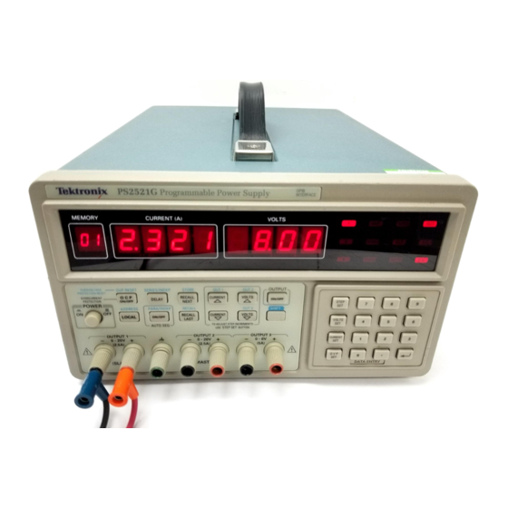
This section describes how to use the front panel controls and how to make connections to the power supply. Functional Overview Figure 3 illustrates the front panel features of the PS2520, PS2520G, PS2521, and PS2521G Programmable Power Supplies. Amperes Volts... -
Page 20: Making A Control Setting
To enter a number, for example, you must select the function, enter the number, and then press return ( ). This manual presents an entry sequence of this type in the following form: Press (function) (number) (return PS2520, PS2520G, PS2521 & PS2521G User Manual... -
Page 21: Selecting The Output
Press SHIFT OUT(n) to select the output. Example: Select Output 2. SHIFT OUT2 The output indicator for Output 2 lights, and you can set the output levels. PS2520, PS2520G, PS2521 & PS2521G User Manual... -
Page 22: Setting The Protection Levels
Setting the OCP Pressing OCP (overcurrent protection on) sets the power supply to automatically disable the outputs upon reaching the current limit. The OCP indicator appears on the display when the OCP is on. PS2520, PS2520G, PS2521 & PS2521G User Manual... -
Page 23: Setting Voltage And Current Limits
3. Set the current limit of the output to 0.3 A: CURRENT SET (return The power supply keeps the voltage constant if the load does not require more than 0.3 amperes. The power supply indicates C.V. on the display. PS2520, PS2520G, PS2521 & PS2521G User Manual... -
Page 24: Setting Voltage And Current Steps
0.5 V. Press CURRENT to increase (and press CURRENT decrease) the current limit by steps of 0.1 A. Press and hold the arrow key to increase the selection speed. PS2520, PS2520G, PS2521 & PS2521G User Manual... -
Page 25: Connecting The Outputs
To reference an output connection to ground, do one of the following: Connect the positive output to the ground terminal to supply a negative voltage across the load. PS2520, PS2520G, PS2521 & PS2521G User Manual... -
Page 26: Independent Operation
When the outputs are in the independent mode of operation, the SERIES and PARA indicators are not lighted. See Figure 7 for examples of independent output connections. PS2520, PS2520G, PS2521 & PS2521G User Manual... -
Page 27: Figure 7: Examples Of Independent Output Connections
Load 1 Load 2 Load 3 Positive-ground and negative-ground connections OUTPUT 1 OUTPUT 2 OUTPUT 3 – – – –V –V Load 1 Load 2 Load 3 Figure 7: Examples of Independent Output Connections PS2520, PS2520G, PS2521 & PS2521G User Manual... -
Page 28: Figure 8: Connecting Power Supplies In Series
60 VDC total or 60 VDC between any connection and earth ground. Refer to Figure 9 for examples of different types of series connec- tions using the three outputs. PS2520, PS2520G, PS2521 & PS2521G User Manual... -
Page 29: Figure 9: Examples Of External Series Connections
Negative-ground OUTPUT 1 OUTPUT 2 OUTPUT 3 – – – Total Load Positive-ground OUTPUT 1 OUTPUT 2 OUTPUT 3 – – – Load = –(V Total Figure 9: Examples of External Series Connections PS2520, PS2520G, PS2521 & PS2521G User Manual... -
Page 30: Figure 10: Connecting Power Supplies In Parallel
Refer to Figure 11 for examples of different types of parallel connections using the three outputs. PS2520, PS2520G, PS2521 & PS2521G User Manual... -
Page 31: Figure 11: Examples Of External Parallel Connections
OUTPUT 2 OUTPUT 3 – – – Maximum 2Max 3Max Load Positive-ground OUTPUT 1 OUTPUT 2 OUTPUT 3 – – – Maximum 1Max 2Max 3Max Load Figure 11: Examples of External Parallel Connections PS2520, PS2520G, PS2521 & PS2521G User Manual... -
Page 32: Master/Slave Operation
(The voltage across Output 1 and Output 2 in series is twice that of Output 2.) The current setting for Output 2 controls the maximum current available to the load. See Figure 12. PS2520, PS2520G, PS2521 & PS2521G User Manual... -
Page 33: Figure 12: Series-Tracking Operation
Output 2 setting. The current available from Output 1 and Output 2 in parallel is twice that of the Output 2 setting. See Figure 13. – – – Master Slave Internal connection Internal connection Total Master Maximum Master Figure 13: Parallel-Tracking Operation PS2520, PS2520G, PS2521 & PS2521G User Manual... -
Page 34: Enabling The Outputs
As the length of the output leads or the amount of output current increases, the amount of voltage drop across the output leads also increases. In this case, the internal sense connection does not accurately measure the voltage across the load. To compensate for PS2520, PS2520G, PS2521 & PS2521G User Manual... -
Page 35: Storing And Recalling Settings
(The section that describes the delay timer operation begins on page 24.) Press SHIFT STORE (memory location number) (return ) to store the settings in memory. PS2520, PS2520G, PS2521 & PS2521G User Manual... -
Page 36: Recalling An Individual Setting
3. Press RECALL NEXT to recall the next memory location in the sequence. Press RECALL LAST to recall the previous memory location in the sequence. PS2520, PS2520G, PS2521 & PS2521G User Manual... - Page 37 Note the current limit setting for location 03 is the same as location 02; therefore, you do not have to re-enter the current limit setting. 7. Set the sequence for memory locations 01 through 03: SHIFT RECALL (return PS2520, PS2520G, PS2521 & PS2521G User Manual...
- Page 38 02: 7 seconds Set the test loop for memory locations 01 and 02. 1. Recall the settings in memory location 01: SHIFT RECALL (return 2. Set the delay time to 3 seconds: DELAY (return PS2520, PS2520G, PS2521 & PS2521G User Manual...
-
Page 39: Setting The Gpib Address
If you have a PS2520G or PS2521G Programmable Power Supply, use the ADDRESS/LOCAL control to set or read the GPIB address of the power supply. Refer to the PS2520G and PS2521G Program- mer Manual for more details. PS2520, PS2520G, PS2521 & PS2521G User Manual... - Page 40 Operating Basics PS2520, PS2520G, PS2521 & PS2521G User Manual...
-
Page 41: Appendix A: Specifications
Appendix A: Specifications Tables 2 through 5 list the specifications of the PS2520, PS2520G, PS2521, and PS2521G Programmable Power Supplies. Table 2: Operating Characteristics Name Characteristic Independent Output PS2520 and PS2520G: Ratings two outputs 0 to 36 V, 0 to 1.5 A and... - Page 42 Current: 150 ppm + 10 mA Drift Voltage: 0.03% + 6 mV Current: 0.1% + 6 mA Series Tracking tracking error Voltage: 0.1% + 50 mV load effect Voltage: 50 mV source effect Voltage: 3 mV PS2520, PS2520G, PS2521 & PS2521G User Manual...
-
Page 43: Table 3: Electrical Characteristics
Description Power Source 100, 120, and 220 VAC, 10% 50 – 60 Hz 240 VAC –10% + 4.2% 50 – 60 Hz Safety ETL listed to UL 1244 Certified to CSA–C22.2 No 231–M89 PS2520, PS2520G, PS2521 & PS2521G User Manual... -
Page 44: Table 4: Environmental Characteristics
0 C to +40 C (+32 F to +104 F) Table 5: Physical Characteristics Name Description Overall Dimensions Width: 255 mm (10.0 in) Height: 145 mm (5.7 in) Depth: 346 mm (13.6 in) Weight 10 kg (22 lbs) PS2520, PS2520G, PS2521 & PS2521G User Manual... -
Page 45: Appendix B: Maintenance
To arrange for warranty service or to get an estimate on a product that is out of warranty, call your local Tektronix office. If you are within the continental U.S., you may call 1-800-TEK-WIDE (1-800-835-9433) for assistance. When you call, have the serial number of the power supply available. -
Page 46: Repackaging For Shipment
5. Seal the shipping carton with an industrial stapler or strapping tape. 6. Call your local Tektronix office for shipping instructions. If you are within the continental U.S., you may call 1-800-TEK-WIDE (1-800-835–9433) for assistance. Troubleshooting If the power supply does not function properly, refer to Table 6 to eliminate operating faults. -
Page 47: Table 6: Troubleshooting Steps
The power supply indicates an error in setup or operation by displaying the message “Err –xxx” on the front panel. Table 7 lists each message number and explains what the error code means. PS2520, PS2520G, PS2521 & PS2521G User Manual... -
Page 48: Table 7: Error Messages
“Setting conflict; Voltage setting error” –068 “Setting conflict; Current setting error” –069 “Setting conflict; Recall setting error” –070 “Setting conflict; Store setting error” –091 “Device-specific error; Calibration current full-scale error” –092 “Device-specific error; Calibration voltage full-scale error” PS2520, PS2520G, PS2521 & PS2521G User Manual... - Page 49 Appendix B: Maintenance Table 7: Error Messages (Cont.) Front Panel Error Code Description –093 “Device-specific error; Calibration overvoltage protection full-scale error” –094 “Device-specific error; Calibration overvoltage protection offset error” PS2520, PS2520G, PS2521 & PS2521G User Manual...
- Page 50 Appendix B: Maintenance PS2520, PS2520G, PS2521 & PS2521G User Manual...
-
Page 51: Appendix C: Replaceable Parts
The items listed in Table 9 are available as optional accessories: Table 9: Optional Accessories Accessory Tektronix Part Number Fuse,3AG, 2A, 250V,SB 159–0023–00 (198 – 250 V operation) 230V Power Cords Refer to Table 10 PS2520, PS2520G, PS2521 & PS2521G User Manual... -
Page 52: Table 10: Accessory Power Cords
Tektronix Part Plug Configuration Normal Usage Number North America 161-0104-00 115 V Europe 161-0104-06 230 V United Kingdom 161-0104-07 230 V Australia 161-0104-05 230 V North America 161-0104-08 230 V Switzerland 161-0167-00 230 V PS2520, PS2520G, PS2521 & PS2521G User Manual... -
Page 53: Index
DELAY, 24 entry sequence, 6 front panel, 5 keypad, use of, 9 features LOCAL, 25 front panel, 5 OCP, 8 product, 1 OUTPUT, 20 rear panel, 6 output selection, 7 fuse, replacement, 3 PS2520, PS2520G, PS2521 & PS2521G User Manual... - Page 54 2, 6 power connector, depicted, 6 power cord, installation, 3 power switch, depicted, 5 procedure, general operation, 4 maintenance, 31 master/slave operation, 18 memory indicator, depicted, 5 recalling stored settings, 22 memory locations PS2520, PS2520G, PS2521 & PS2521G User Manual...
- Page 55 VOLTS readout, depicted, 5 series tracking, 18 VOLTS steps, setting, 10 shipment, repackaging for, 32 specifications, 27 standard accessories, 37 status indicators, depicted, 5 STEP SET function, procedure for, warranty service, 31 weight, 30 PS2520, PS2520G, PS2521 & PS2521G User Manual...
- Page 56 Index PS2520, PS2520G, PS2521 & PS2521G User Manual...
Need help?
Do you have a question about the PS2520 and is the answer not in the manual?
Questions and answers