
Related Manuals for Tektronix PWS4205


Summary of Contents for Tektronix PWS4205
- Page 1 PWS4205, PWS4305, PWS4323, PWS4602, and PWS4721 Linear DC Power Supplies User Manual *P071276101* 071-2761-01...
- Page 3 PWS4205, PWS4305, PWS4323, PWS4602, and PWS4721 Linear DC Power Supplies User Manual www.tektronix.com 071-2761-01...
- Page 4 Copyright © Tektronix. All rights reserved. Licensed software products are owned by Tektronix or its subsidiaries or suppliers, and are protected by national copyright laws and international treaty provisions. Tektronix products are covered by U.S. and foreign patents, issued and pending. Information in this publication supersedes that in all previously published material.
- Page 5 Warranty Tektronix warrants that the product will be free from defects in materials and workmanship for a period of three (3) years from the date of original purchase from an authorized Tektronix distributor. If the product proves defective during this warranty period, Tektronix, at its option, either will repair the defective product without charge for parts and labor, or will provide a replacement in exchange for the defective product.
-
Page 7: Table Of Contents
Front-panel Operation......................Index PWS4205, PWS4305, PWS4323, PWS4602, and PWS4721 User Manual... - Page 8 Table of Contents PWS4205, PWS4305, PWS4323, PWS4602, and PWS4721 User Manual...
-
Page 9: General Safety Summary
Do not operate in an explosive atmosphere. Keep product surfaces clean and dry. Provide proper ventilation. Refer to the manual’s installation instructions for details on installing the product so it has proper ventilation. PWS4205, PWS4305, PWS4323, PWS4602, and PWS4721 User Manual... - Page 10 DANGER indicates an injury hazard immediately accessible as you read the marking. WARNING indicates an injury hazard not immediately accessible as you read the marking. CAUTION indicates a hazard to property including the product. The following symbol(s) may appear on the product: PWS4205, PWS4305, PWS4323, PWS4602, and PWS4721 User Manual...
-
Page 11: Compliance Information
Under the factory default settings, output voltage and current limit values will be restored to the previous settings, but output state will be set to off. Change the user preferences if restoration of previous output state upon restoration of AC input power is desired. PWS4205, PWS4305, PWS4323, PWS4602, and PWS4721 User Manual... - Page 12 CISPR 11:2003. Radiated and Conducted Emissions, Group 1, Class A, in accordance with EN 61326-1:2006. Australia / New Zealand contact. Baker & McKenzie Level 27, AMP Centre 50 Bridge Street Sydney NSW 2000, Australia PWS4205, PWS4305, PWS4323, PWS4602, and PWS4721 User Manual...
-
Page 13: Safety Compliance
These are sheltered locations where neither temperature nor humidity is controlled. The area is protected from direct sunshine, rain, or direct wind. Pollution Degree 4. Pollution that generates persistent conductivity through conductive dust, rain, or snow. Typical outdoor locations. PWS4205, PWS4305, PWS4323, PWS4602, and PWS4721 User Manual... - Page 14 Measurement Category II. For measurements performed on circuits directly connected to the low-voltage installation. Measurement Category I. For measurements performed on circuits not directly connected to MAINS. Overvoltage Category Overvoltage Category II (as defined in IEC 61010-1) viii PWS4205, PWS4305, PWS4323, PWS4602, and PWS4721 User Manual...
-
Page 15: Environmental Considerations
For information about recycling options, check the Support/Service section of the Tektronix Web site (www.tektronix.com). Restriction of Hazardous Substances This product is classified as Monitoring and Control equipment, and is outside the scope of the 2002/95/EC RoHS Directive. PWS4205, PWS4305, PWS4323, PWS4602, and PWS4721 User Manual... -
Page 16: Preface
Programmable DC power supply. 32 V, 3 A, 1 channel, USB PWS4602 Programmable DC power supply. 60 V, 2.5 A, 1 channel, USB PWS4721 Programmable DC power supply. 72 V, 1.2 A, 1 channel, USB PWS4205, PWS4305, PWS4323, PWS4602, and PWS4721 User Manual... -
Page 17: Getting Started
Getting Started Standard Accessories Tektronix part Accessory number PWS4205, PWS4305, PWS4323, PWS4602, and PWS4721 Power Supply User Manual (available 071-2761-XX to in 10 languages) Contains safety and installation information. 071-2770-XX Power Cord: based upon the international power option (See page 1,... -
Page 18: Specifications
Tektronix GPIB to USB Adapter. Enables GPIB control of Tektronix instruments through the TEK-USB-488 USB port of Tektronix instruments Specifications For more specifications, refer to the PWS4205, PWS4305, PWS4323, PWS4602, and PWS4721 Technical Reference. Table 2: Electrical ratings for the power connection Line Selector Model... -
Page 19: Operating Requirements
Do not loosen any screw on this product, except those in the rear connector, which are intended to retain attached external wires to the connector. There are no user serviceable components inside. PWS4205, PWS4305, PWS4323, PWS4602, and PWS4721 User Manual... -
Page 20: Installing The System
If there is more than one load, then every pair of load wires must be capable of safely carrying the full-rated current of the power supply. PWS4205, PWS4305, PWS4323, PWS4602, and PWS4721 User Manual... - Page 21 Push V-set, use the number keys to set the voltage value to 0 and push Enter. Check if the displayed voltage value is approximately 0 V and check if the displayed current value is approximately 0 A. You can confirm the 0 V setting with a voltmeter. PWS4205, PWS4305, PWS4323, PWS4602, and PWS4721 User Manual...
-
Page 22: Cleaning
To avoid damage to the surface of the power supply, do not use any abrasive or chemical cleaning agents. CAUTION. Avoid getting moisture inside the unit during external cleaning. Use only enough cleaning solution to dampen the cloth or swab. PWS4205, PWS4305, PWS4323, PWS4602, and PWS4721 User Manual... -
Page 23: Operating Basics
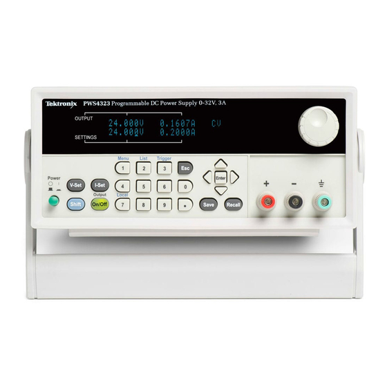
7. Number keys (0 to 9 and Esc) for direct numeric entry 8. V-Set, I-Set, Shift, and Output On/Off function buttons 9. Power switch Function button descriptions Button Description Sets the voltage limit Sets the current limit PWS4205, PWS4305, PWS4323, PWS4602, and PWS4721 User Manual... -
Page 24: Menu Descriptions
Menu descriptions Primary Menu Secondary Menu Description >Default Returns the instrument to the factory default setup values. This does not change the setup memory or lists PWS4205, PWS4305, PWS4323, PWS4602, and PWS4721 User Manual... - Page 25 >Key Beep Turns on or off a beeper sound when you push a button or press a key. “On” enables the key sound. “Off” disables it. >Knob Lock Locks the multipurpose knob PWS4205, PWS4305, PWS4323, PWS4602, and PWS4721 User Manual...
- Page 26 Constant current mode OVP (upper) OVP has tripped Output has been turned off by the remote inhibit (RI) input Lower display messages OVP (lower) Overvoltage protection (OVP) is set. Flashes when OVP has tripped PWS4205, PWS4305, PWS4323, PWS4602, and PWS4721 User Manual...
-
Page 27: Rear Panel At A Glance
The four Control In + - and Control Out + - connectors on the rear panel terminal strip are configured by the port mode controls. They support the trigger, RI/DFI, and digital I/O functions. PWS4205, PWS4305, PWS4323, PWS4602, and PWS4721 User Manual... -
Page 28: Front-Panel Operation
If the front panel was locked with a password, enter the correct password after you push the function buttons (V-set, I-set, Save, Recall, or Shift), then you can change the settings. NOTE. To cancel a function operation (V-set, I-set, Save, Recall, or Shift), push the Esc button. PWS4205, PWS4305, PWS4323, PWS4602, and PWS4721 User Manual... - Page 29 Knob Lock = Off Trig Source = Manual OVP Set = Off Max Volt Set = Off Out Time Set = Off Output Recall = Off Save Last = On Key Beep = Off PWS4205, PWS4305, PWS4323, PWS4602, and PWS4721 User Manual...
-
Page 30: Setting The Current Limit
3. Push Enter to confirm the memory location. Recalling setups. 1. Push Recall. 2. Use the number keys or the arrow keys to select the setup memory that you want to recall from. 3. Push Enter. PWS4205, PWS4305, PWS4323, PWS4602, and PWS4721 User Manual... - Page 31 9. Push Enter. NOTE. The lower display shows OVP when the over voltage protection feature is activated. The OVP indicator will flash on and off when the over voltage protection feature has tripped. PWS4205, PWS4305, PWS4323, PWS4602, and PWS4721 User Manual...
- Page 32 4. Use the arrow keys to select Save Last. 5. Push Enter. 6. Use the arrow keys to select On or Off. 7. Push Enter. 8. Push Esc to exit the menu system. PWS4205, PWS4305, PWS4323, PWS4602, and PWS4721 User Manual...
- Page 33 (See page 11, Rear Panel at a Glance.) 2. Connect to your device under test using two wires from either the front panel binding posts or the rear panel DRIVE + and DRIVE - terminals. PWS4205, PWS4305, PWS4323, PWS4602, and PWS4721 User Manual...
- Page 34 3. Push Enter. Recall 1 4. Rotate the multipurpose knob to select Recall 1 the number of the list to define or edit. You can choose from 1 to 7. 5. Push Enter. Continuous PWS4205, PWS4305, PWS4323, PWS4602, and PWS4721 User Manual...
- Page 35 12. Use the keypad to set the voltage for S 001 = 4.00V this step. In the example to the right, the voltage is set to 4.00 volts. 13. Push Enter. S 001 = 0.1000A PWS4205, PWS4305, PWS4323, PWS4602, and PWS4721 User Manual...
- Page 36 0.100 seconds. 17. Push Enter. S 002 = 4.500 V 18. Repeat steps 11 through 17 for each of Save List 1 the number of steps selected in step 10 above. PWS4205, PWS4305, PWS4323, PWS4602, and PWS4721 User Manual...
- Page 37 See the Programmer’s Manual for instructions on programming the List Mode Function. Connect to an External Computer with USB 1. Load VISA on your computer. You can do this with the national Instruments LabVIEW SignalExpress CD that accompanies your power supply. PWS4205, PWS4305, PWS4323, PWS4602, and PWS4721 User Manual...
- Page 38 USB Device port on the rear panel of the TEK-USB-488 adapter. Alternatively, connect the output power cable from an optional AC power unit to the 5 VDC connector on the rear panel of the adapter. PWS4205, PWS4305, PWS4323, PWS4602, and PWS4721 User Manual...
- Page 39 To do this, first, push Shift and then Menu (1). 6. Use the up and down arrow keys to select >System 7. Push Enter. 8. Use the up and down arrow keys to select >Address. 9. Push Enter. PWS4205, PWS4305, PWS4323, PWS4602, and PWS4721 User Manual...
- Page 40 Operating Basics 10. Use the up and down arrow keys to select the desired GPIB address for the power supply. 11. Push Esc to exit the menu system. PWS4205, PWS4305, PWS4323, PWS4602, and PWS4721 User Manual...
-
Page 41: Index
Shorting clip, 12 Specifications, 2 Standard accessories, 1 No power, 5 Features, x Front panel, 12 Front panel indicators and buttons, 7 TEK-USB-488 Adapter, 22 On/off button, 8 Troubleshooting, 5 Operating requirements, 3 PWS4205, PWS4305, PWS4323, PWS4602, and PWS4721 User Manual... - Page 42 Index Voltage limit adjustment, 14 Volts display, 7 USB Device port, 11 V-set button, 7 PWS4205, PWS4305, PWS4323, PWS4602, and PWS4721 User Manual...
Need help?
Do you have a question about the PWS4205 and is the answer not in the manual?
Questions and answers