
Related Manuals for Tektronix KEITHLEY 2200 Series


Summary of Contents for Tektronix KEITHLEY 2200 Series
- Page 1 www.keithley.com Series 2200 Multichannel Programmable DC Power Supplies Programming Technical Reference 2220S-907-01 Rev. B / Dec 2013...
- Page 3 Series 2200 Multichannel Programmable DC Power Supplies Programming Technical Reference © 2013, Keithley Instruments, Inc. Cleveland, Ohio, U.S.A. All rights reserved. Any unauthorized reproduction, photocopy, or use the information herein, in whole or in part, without the prior written approval of Keithley Instruments, Inc. is strictly prohibited. All Keithley Instruments product names are trademarks or registered trademarks of Keithley Instruments, Inc.
- Page 4 Safety precautions The following safety precautions should be observed before using this product and any associated instrumentation. Although some instruments and accessories would normally be used with nonhazardous voltages, there are situations where hazardous conditions may be present. This product is intended for use by qualified personnel who recognize shock hazards and are familiar with the safety precautions required to avoid possible injury.
- Page 5 For safety, instruments and accessories must be used in accordance with the operating instructions. If the instruments or accessories are used in a manner not specified in the operating instructions, the protection provided by the equipment may be impaired. Do not exceed the maximum signal levels of the instruments and accessories, as defined in the specifications and operating information, and as shown on the instrument or test fixture panels, or switching card.
-
Page 7: Table Of Contents
Table of Contents Preface ......................Welcome ....................... Products......................Extended Warranty ................... Contact Information ..................Getting Started Getting Started ....................Using the USB interface ..................Using the GPIB interface ................... Command Timing.................... Command Syntax....................Command and Query Structure ................Command Entry....................Command Groups .................... - Page 8 Table of Contents Appendices Appendix A: ASCII Code Chart ................Appendix B: Programming Examples................. Appendix C: Default Setup ..................Series 2200 Programmable Multichannel DC Power Supplies Programmer Manual...
-
Page 9: Preface
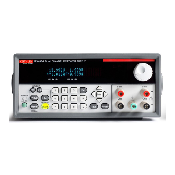
Preface Welcome Thank you for using a Keithley Instruments product. The Series 2200 Multichannel Programmable DC Power Supplies are flexible DC sources designed to power a wide range of applications. The model 2230-30-1 and its variants offer three power channels and the model 2220-30-1 and its variants provide two channels. -
Page 10: Extended Warranty
Preface Extended Warranty Additional years of warranty coverage are available on many products. These valuable contracts protect you from unbudgeted service expenses and provide additional years of protection at a fraction of the price of a repair. Extended warranties are available on new and existing products. Contact your local Keithley Instruments representative for details. -
Page 11: Getting Started
Getting Started... -
Page 13: Using The Usb Interface
Getting Started Your power supply has a USB 2.0 high-speed device port to control the power supply using the USBTMC protocol. The USBTMC protocol allows USB devices to communicate using IEEE-488.2 style messages. If you have a G-version, you can also remotely communicate between your power supply and PC over GPIB. -
Page 14: Command Timing
Getting Started The power supply is now set up for bidirectional communication with your controller. Command Timing The average time it takes to both send and receive every command is approximately 20 ms. In the case of more complex commands, more time may be required to complete transmission. -
Page 15: Command Syntax
Command Syntax You can control the power supply through the USB interface or the GPIB interface (G-version instruments only) using commands and queries. This section describes the syntax these commands and queries use and the conventions the power supply uses to process them. The commands and queries themselves are listed by group and alphabetically. - Page 16 Command Syntax Table 2-2: Command message elements Symbol Meaning <Header> The basic command name. If the header ends with a question mark, the command is a query. The header may begin with a colon (:) character; if the command is concatenated with other commands the beginning colon is required.
-
Page 17: Command Entry
Command Syntax You can specify a query command at any level within the command tree unless otherwise noted. These branch queries return information about all the mnemonics below the specified branch or level. Query Responses When a query is sent to the power supply, only the values are returned. When the returned value is a mnemonic, it is noted in abbreviated format, as shown in the following table. - Page 18 Command Syntax You can create commands and queries from these subsystem hierarchy trees. Commands specify actions for the instrument to perform. Queries return measurement data and information about parameter settings. Message Terminators This manual uses the term <EOM> (End of message) to represent a message terminator.
- Page 19 Command Syntax Abbreviating Commands, You can abbreviate most SCPI commands, queries, and parameters to an accepted short form. This manual shows these commands as a combination of upper and Queries, and Parameters lower case letters. The upper case letters indicate the accepted short form of a command, as shown in the following figure.
- Page 20 Command Syntax General Rules for Using The following are three general rules for using SCPI commands, queries, and parameters: SCPI Commands You can use single (‘ ’) or double (“ ”) quotation marks for quoted strings, but you cannot use both types of quotation marks for the same string. correct “This string uses quotation marks correctly.”...
-
Page 21: Command Groups
Command Groups This manual lists the power supply commands in two ways. First, it presents them by functional groups. Then, it lists them alphabetically. The functional group list starts below. The alphabetical list provides detail on each command. (See page 2-13.) The power supply interface conforms to Keithley standard codes and formats except where noted. -
Page 22: Save And Recall Commands
Command Groups Table 2-5: Status commands (cont.) Command Description STATus:QUEStionable:INSTrument:ISUMmary<x>:CONDition? Return questionable condition register summary for channel x, where <x> is 1, 2, or 3. When a bit of the quest condition changes, the corresponding bit value in the quest event register will be set to x. -
Page 23: System Commands
Command Groups System Commands Table 2-7: System commands Header Description SYSTem:POSetup Set or query power-on parameters SYSTem:MODUle? Queries the module of the power supply SYSTem:VERSion? Return SCPI version information SYSTem:MODUle? Return error code and error information SYSTem:KEY Set or query key operation SYSTem:REMote Set or query remote mode SYSTem:RWLock... -
Page 24: Trigger Commands
Command Groups Trigger Commands Trigger commands are used to determine the timing of list mode sequences. Table 2-10: Trigger commands Header Description TRIGger[:IMMediate] Forces an immediate trigger event. *TRG Generates a trigger event. [SOURce:]VOLTage:TRIGgered[:IMMediate] Set or query the trigger voltage. [SOURce:]CURRent:TRIGgered[:IMMediate] Set or query the trigger current. -
Page 25: Measurement Commands
Command Groups Measurement Commands Measurement commands are used to query parameters. The commands MEASure initiate and execute a complete measurement cycle and are recommended for measuring voltage and current at the outputs of the power supply. FETCh commands do not initiate a new measurement cycle but rely on measurements stored in the communication buffers of the power supply. -
Page 26: Channel Combination Commands
Command Groups Table 2-12: Source commands (cont.) Command Description [SOURce:]OUTPut:ENABle Set or query the current channel as enabled or disabled. [SOURce]:CHANnel:OUTPut:[STATe] Set or query the output status of the current channel. [SOURce:]APPly Sets voltage and current level and switch channels at the same time. -
Page 27: Commands Listed In Alphabetical Order
Commands Listed in Alphabetical Order You can use commands to either set instrument features or query instrument values. You can use some commands to do both, some only to set and some only to query. This document marks set-only commands with the words “No Query Form”... - Page 28 Commands Listed in Alphabetical Order Syntax DISPlay[:WINDow]:TEXT[:DATA] <string> DISPlay[:WINDow]:TEXT[:DATA]? Arguments String with quotes. 48 character length limit. DISPlay[:WINDow]:TEXT:CLEar (No Query Form) Clears the characters on the display and then returns the display to normal mode. Group Display Syntax DISPlay[:WINDow]:TEXT:CLEar Arguments None *ESE Sets and queries the bits in the Event Status Enable Register (ESER).
- Page 29 Commands Listed in Alphabetical Order might return the string , showing that the ESER contains the *ESE *ESE 186 binary value 10111010. *ESR? (Query Only) Returns the contents of the Standard Event Status Register (SESR). *ESR? also clears the SESR (since reading the SESR clears it). (See page 3-1, Status and Events.) Group Status...
- Page 30 Commands Listed in Alphabetical Order Returns , which gives is the measured output current in amperes. <NR2> Examples might return 0.09998, which would be the current measured at the FETC:CURR? output of the power supply in amperes. FETCh[:SCALar]:VOLTage[:DC]? (Query Only) This command returns the last measured output voltage stored in the communications buffer of the power supply.
- Page 31 Commands Listed in Alphabetical Order *IDN? (Query Only) Returns the power supply identification code in IEEE 488.2 notation. Group Status Syntax *IDN? Returns A string that includes <manufacturer>, <model>, <serial number>, and <firmware_version> as defined in the following table. <manufacturer> <model>...
- Page 32 Commands Listed in Alphabetical Order Instrument Group Syntax INSTrument:COMbine:OFF Related Commands INSTrument:COMbine? Examples INSTRUMENT:COMBINE:OFF INSTrument:COMbine:PARAllel (No Query Form) This command sets CH1 and CH2 into parallel mode. This mode assumes that CH1 and CH2 have been wired in parallel external to the power supply. The combined channel should be referred to as CH1 and the current for the combined channel may be set as high as 3A.
- Page 33 Commands Listed in Alphabetical Order Related Commands INSTrument:COMbine:OFF, INSTrument:COMbine:PARAllel, INSTrument:COMbine:TRACk Examples INSTRUMENT:COMBINE:SERIES INSTrument:COMbine:TRACk (No Query Form) This command sets CH1 and CH2 in track mode. In this mode, the ratio of CH1 to CH2 voltage that is set before sending the command will be maintained for subsequent voltage settings.
- Page 34 Commands Listed in Alphabetical Order Examples INST:COUP CH1,CH2 INSTrument:SELect This command is used to switch the current channel command. Group Channel Syntax INSTrument:SELect {CH1|CH2|CH3} INSTrument:SELect? Arguments are the channels you can switch the instrument to. CH1, CH2, or CH3 Availability of channels depends on which model of power supply you have. MEASure[:SCALar]:CURRent[:DC]? (Query Only) This command initiates and executes a new current measurement, and returns the measured output current of the power supply.
- Page 35 Commands Listed in Alphabetical Order Measurement Group Syntax MEASure[:SCALar]:POWer[:DC]? [CH1|CH2|CH3|ALL] Related Commands FETCh[:SCALar]:POWer[:DC]?, INSTrument:SELect Arguments is the channel on which to read the output power. CH1, CH2, or CH3 is to read the output power on all channels. Returns is the measured output power in watts. <NR2>...
- Page 36 Commands Listed in Alphabetical Order *OPC This command configures the instrument to generate an operation complete message by setting bit 0 of the Standard Event Status Register (SESR) when all pending commands that generate an OPC message are complete. The query command places the ASCII character "1" into the output queue when all such OPC commands are complete.
- Page 37 Commands Listed in Alphabetical Order Examples *PSC 0 sets the power-on status clear flag to false. *PSC might return 1, indicating that the power-on status clear flag is set to true. *RCL (No Query Form) Restores the state of the power supply from a copy of its settings stored in the setup memory.
- Page 38 Commands Listed in Alphabetical Order The *RST command does not change the following items: State of the USB or GPIB interface Calibration data that affects device specifications Current GPIB power supply address Stored settings Output queue Service Request Enable Register settings Standard Event Status Enable Register settings Power-On Status Clear flag setting front-panel LOCK state...
- Page 39 Commands Listed in Alphabetical Order [SOURce:]APPly (No Query Form) This command is used to select channels and set voltage and current level using a single command. Group Source Syntax [SOURce:]APPly {CH1|CH2|CH3},[Voltage|Max|Min],[Current|Max|Min] [SOURce:]APPly [CH1|CH2|CH3] Related Commands This command can replace the following commands: INST CH1, VOLT 3V, and CURR 1A.
- Page 40 Commands Listed in Alphabetical Order Syntax [SOURce]:CHANnel:OUTPut:[STATe] {0|1|ON|OFF} [SOURce]:CHANnel:OUTPut:[STATe]? Related Commands INSTrument:SELect Arguments indicates that the channel is off. indicates that the channel is on. Examples would turn whichever channel had been selected using CHANNEL:OUTPUT OFF command to the off state. INSTRUMENT might return 0 to indicate that the current channel is off.
- Page 41 Commands Listed in Alphabetical Order Arguments is a flexible decimal number (NRf) that may be type NR1, NR2 or <Current> NR3. It specifies a level between the minimum current and maximum nameplate current level for the power supply. sets the current to the minimum level (0 A). sets the current to the maximum level.
- Page 42 Commands Listed in Alphabetical Order Syntax [SOURce:]CURRent:TRIGgered[:IMMediate] {<current>|MIN|MAX} [SOURce:]CURRent:TRIGgered[:IMMediate]? Related Commands INSTrument:SELect Arguments is a flexible decimal number (NRf) that may be type NR1, NR2 or <Current> NR3. It specifies a level between the minimum current and maximum nameplate current level for the power supply. sets the current to the minimum level (0 A).
- Page 43 Commands Listed in Alphabetical Order Arguments disables the current channel. enables the current channel. Returns Disabled Enabled [SOURce:]OUTPut:PARallel[:STATe] This command sets the parallel state of CH1 and CH2. Group Source Syntax [SOURce:]OUTPut:PARallel[:STATe] 0|1|OFF|ON [SOURce:]OUTPut:PARallel[:STATe]? Arguments sets the parallel state to off. sets the parallel state to on.
- Page 44 Commands Listed in Alphabetical Order Examples OUTPUT:PON RST might return , which would indicate that the instrument will OUTPUT:PON? RCL0 return to the present output state if the power is cycled. [SOURce:]OUTPut:SERies This command sets the serial state of CH1 and CH2. Group Source Syntax...
- Page 45 Commands Listed in Alphabetical Order [SOURce:]OUTPut:TIMer:DELay This command sets the time duration of the output timer for the currently selected channel. When the timer is activated and a duration is set, the specified output of the power supply will turn off automatically if left on longer than the specified duration.
- Page 46 Commands Listed in Alphabetical Order Group Source Syntax [SOURce:]OUTPut:TIMer[:STATe] {0|1|ON|OFF} [SOURce:]OUTPut:TIMer[:STATe]? Related Commands [SOURce:]OUTPut:TIMer:DELay, [SOURce:]OUTPut[:STATe][:ALL], INSTrument:SELect Arguments turns the output timer off. turns the output timer on. Returns Examples To activate the timer, first send , then send OUTPUT:TIMER:STATE ON OUTPUT:STATE ON To turn the timer off, send OUTPUT:TIMER:STATE OFF...
- Page 47 Commands Listed in Alphabetical Order Syntax [SOURce:]VOLTage[:LEVel][IMMediate][:AMPLitude] {<voltage>|MIN|MAX} [SOURce:]VOLTage[:LEVel][IMMediate][:AMPLitude]? Related Commands [SOURce:]VOLTage[:LEVel]:DOWN[:IMMediate][:AMPLitude] [SOURce:]VOLTage[:LEVel]:UP[:IMMediate][:AMPLitude] [SOURce:]VOLTage[:LEVel][:IMMediate]:STEP[:INCRement] INSTrument:SELect Arguments is a flexible decimal number (NRf) that may be type NR1, NR2 or <voltage> NR3. It specifies the voltage setting, which can range from 0 to the maximum nameplate voltage of the power supply.
- Page 48 Commands Listed in Alphabetical Order [SOURce:]VOLTage[:LEVel]:UP[:IMMediate][:AMPLitude] [SOURce:]VOLTage[:LEVel][IMMediate][:AMPLitude] INSTrument:SELect Arguments is the voltage in kV, V, mV, or μV. <voltage> [SOURce:]VOLTage[:LEVel]:UP[:IMMediate][:AMPLitude] (No Query Form) This command is used to increase the voltage level of the currently selected channel by a step. The voltage step value can be set by the following command: [SOURce:]VOLTage[:LEVel][:IMMediate]:STEP[:INCRement] Group Source...
- Page 49 Commands Listed in Alphabetical Order sets the voltage level to decrease a step. DOWN is the default level (1 V). Returns The voltage in kV, V, mV, or uV. [SOURce:]VOLTage:LIMit[:LEVel] This command limits the maximum voltage that can be programmed on the power supply.
- Page 50 Commands Listed in Alphabetical Order Group Source Syntax [SOURce:]VOLTage:LIMit:STATe {0|OFF|1|ON} [SOURce:]VOLTage:LIMit:STATe? Related Commands INSTrument:SELect [SOURce:]VOLTage:LIMit[:LEVel] Arguments turns off the maximum voltage limit. turns it on. Examples VOLTAGE:LIMIT:STATE ON [SOURce:]VOLTage:TRIGgered[:IMMediate] This command is used to set the voltage level for the trigger function. The command queues the next setting for the currently selected channel.
- Page 51 Commands Listed in Alphabetical Order *SRE (Service Request Enable) sets and queries the bits in the Service Request Enable Register (SRER). Refer to the Status and Events chapter for more information. Group Status Syntax *SRE <NR1> *SRE? Related Commands *CLS, *ESR?, *PSC Arguments is an integer value in the range from 0 to 255.
- Page 52 Commands Listed in Alphabetical Order Returns <mask> Examples STATUS:OPERATION:ENABLE ? might return STATUS:OPERATION:ENABLE STATus:OPERation[:EVENt]? (Query Only) This command returns the contents of the operation event register (OEVR). After executing this command the operation event register is reset. Details about status registers are available in this manual.
- Page 53 Commands Listed in Alphabetical Order Returns <mask> Examples might return , which would STATUS:OPERATION:INSTRUMENT[:ENABLE]? indicate that only the Constant Current bit of the Operation Enable Register would affect the OPER bit of the Status Byte Register. STATus:OPERation:INSTrument[:EVENt]? (Query Only) This command returns the contents of the operation event register. After executing this command the operation event register is reset.
- Page 54 Commands Listed in Alphabetical Order Returns is a decimal integer ranging from 0 through 255. The binary bits of the <NR1> specified channel's operation enable register are set according to this value. STATus:OPERation:INSTrument:ISUmmary<x>:ENABle This command is used to modify or query the operation enable register of a channel, where <x>...
- Page 55 Commands Listed in Alphabetical Order Examples might return , which STATUS:OPERATION:INSTRUMENT:ISUMMARY1:EVENT? indicates that channel 1 is turned on and in constant voltage mode. STATus:QUEStionable:ENABle This command sets and queries the contents of the questionable enable register (QENR). The QENR is an eight-bit mask register that determines which bits in the Questionable Event Register (QEVR) will affect the state of the QUES bit in the Status Byte Register (SBR).
- Page 56 Commands Listed in Alphabetical Order Returns is a decimal integer representation of the contents of the Questionable <NR1> Event Register (QEVR), ranging from 0 to 255. Examples might return , which would indicate an over STATUS:QUESTIONABLE:EVENT? voltage condition. STATus:QUEStionable:INSTrument:ENABle This command queries the questionable instrument status event register of the instrument.
-
Page 57: Status And Events
Commands Listed in Alphabetical Order Examples might return , which would STATUS:QUESTIONABLE:INSTRUMENT:EVENT? indicate an over voltage condition. STATus:QUEStionable:INSTrument:ISUMmary<x>:CONDition? (Query Only) This queries the questionable condition register (QCR) summary of a channel, where <x> is 1, 2, or 3. 1, 2, and 3 are channel 1, 2, and 3, respectively. Only 1 and 2 are available on two channel instruments. - Page 58 Commands Listed in Alphabetical Order STATus:QUESTionable:INSTrument:ISUMmary<x>:[EVENt]? (Query Only) This queries the operation event register of summary of a channel, where <x> is 1, 2, or 3. 1, 2, and 3 are channel 1, 2, and 3, respectively. Only 1 and 2 are available on two channel instruments.
- Page 59 Commands Listed in Alphabetical Order Group System Syntax SYSTem:ERRor? Returns <NR1>,<error_text> <error_text> ::= <string> where is a description of the error. <string> Examples might return , which means No Input Command to parse. SYSTEM:ERROR? SYSTem:KEY This command can produce the same effect as pressing one of the front-panel buttons.
- Page 60 Commands Listed in Alphabetical Order Front-panel button <NR1> key code KEY_4 KEY_5 KEY_6 KEY_7 KEY_8 KEY_9 KEY_DECIMAL KEY_ESC KEY_ENTER KEY_ON KEY_SHIFT MENU Examples would simulate a press of the Shift key. SYSTEM:KEY 64 SYSTem:LOCal (No Query Form) This command sets the power supply for control from the front-panel. Group System Syntax...
- Page 61 Commands Listed in Alphabetical Order Syntax SYSTem:MODUle? Returns <> where is a description of the error. <string> Examples might return , which means ?. SYSTEM:MODULE? SYSTem:POSetup This command determines how the power supply initializes when its power switch is turned on. This command configures the instrument to power up with default settings, or power up with the settings that were in effect when the instrument was turned off.
- Page 62 Commands Listed in Alphabetical Order Related Commands SYSTem:LOCal, SYSTem:RWLock Arguments None. Examples SYSTEM:REMOTE SYSTem:RWLock (No Query Form) If the power supply is in remote mode, this command locks out the front panel. This command has no effect if the instrument is in local mode. Group System Syntax...
- Page 63 Commands Listed in Alphabetical Order Group Trigger Syntax *TRG Related Commands TRIGger[:IMMediate] Examples *TRG TRIGger[:IMMediate] (No Query Form) This command forces an immediate trigger event. Group Trigger Syntax TRIGger[:IMMediate] Related Commands *TRG Arguments None. Examples TRIGGER *TST? (Query Only) Initiates a self-test and reports any errors. Group Diagnostic Syntax...
- Page 64 Commands Listed in Alphabetical Order *WAI (No Query Form) This command prevents the instrument from executing further commands or queries until all pending commands are complete. Group Synchronization Syntax *WAI Examples *WAI 2-50 Series 2200 Programmable Multichannel DC Power Supplies Programmer Manual...
-
Page 65: Status And Events
Status and Events... -
Page 67: Status Reporting Structure
Status and Events This section provides details about the status information and events the power supply reports. Status Reporting Structure A diagram is provided showing an outline of the power supply error and event reporting function. (See Figure 3-1.) The error and event reporting system consists of the following four register groups: Status Byte Standard Event Operation Status... - Page 68 Status and Events Figure 3-1: Error and event handling process Series 2200 Programmable Multichannel DC Power Supplies Programmer Manual...
-
Page 69: Registers
Status and Events Registers The registers in the event reporting system fall into two functional groups: Status registers contain information about the status of the power supply. They include the Status Byte Register (SBR), Standard Event Register (SER), the Questionable Status Register (QSR), the Questionable Instrument Status Register (QISR), the Operation Status Register (OSR), and the Operation Instrument Status Register (OISR). - Page 70 Status and Events Table 3-1: SBR bit functions (cont.) Function Shows that information is available in the Error Queue. ———— Not used. ———— Not used. Each bit in an Enable Register corresponds to a bit in an Event Register. In order for an event to be reported to a bit in the Status Byte Register, the corresponding bit in the Enable Register must be set to one.
- Page 71 Status and Events Figure 3-4: OISR bit functions Table 3-3: OISR bit functions Function ———— This bit is not used. ———— This bit is not used. ———— This bit is not used. ———— This bit is not used. INST3 STATus:OPERation:INSTrument:ISUMmary3 reported to INST3.
- Page 72 Status and Events Figure 3-6: QISR bit functions Table 3-5: QISR bit functions Function ———— This bit is not used. ———— This bit is not used. ———— This bit is not used. ———— This bit is not used. ———— This bit is not used. ————...
- Page 73 Status and Events Table 3-6: QSR bit functions (cont.) Function ———— This bit is not used. ———— This bit is not used. ———— This bit is not used. Constant current. Constant voltage. Summary Registers There are two types of summary registers: Operation Instrument Summary Register (OISUR).
- Page 74 Status and Events The Operation Instrument Summary Register (OISUR). The Operation Instrument Summary Register is made up of 8 bits, which note the occurrence of the condition shown here. Table 3-7: OISUR bit functions Function ———— This bit is not used. ————...
-
Page 75: Queues
Status and Events Table 3-8: QISUR bit functions (cont.) Function ———— This bit is not used. ———— This bit is not used. ———— This bit is not used. *PSC Command The *PSC command controls the Enable Register contents at power-on. Sending *PSC 1 sets the Enable Registers at power on as follows: ESER 0 (equivalent to an *ESE 0 command) SRER 0 (equivalent to an *SRE 0 command) -
Page 76: Messages And Codes
Status and Events Messages and Codes Error and event codes with negative values are SCPI standard codes. Error and event codes with positive values are unique to the Series 2200 Programmable Multichannel DC Power Supplies. Table 3-9: No event messages Code Message No events to report;... - Page 77 Status and Events Table 3-11: Execution error messages (EXE bit 4) (cont.) Code Message –222 Data out of range –223 Too much data –224 Illegal parameter value –225 Out of memory –270 Macro error –272 Macro execution error –273 Illegal macro label –276 Macro recursion error –277...
- Page 78 Status and Events System Errors The following table lists the system errors that can occur during power supply operation. Table 3-12: System error messages (DDE bit 3) Code Message –310 System error –350 Too many errors Query Errors The following table lists the query errors that can occur during power supply operation.
- Page 79 Status and Events Device Dependent Errors The following table lists the device errors that can occur during power supply operation. These errors may indicate that the power supply needs repair. Table 3-15: Device dependent error messages (DDE bit 3) Code Message Front panel uart overrun Front panel uart framing...
- Page 80 Status and Events 3-14 Series 2200 Programmable Multichannel DC Power Supplies Programmer Manual...
- Page 81 Appendices...
- Page 83 Appendix A: ASCII Code Chart Series 2200 Programmable Multichannel DC Power Supplies Programmer Manual...
- Page 84 Appendix A: ASCII Code Chart Series 2200 Programmable Multichannel DC Power Supplies Programmer Manual...
- Page 85 Appendix B: Programming Examples Example 1 This example is written in the C programming language; NIVISA can be used. It demonstrates basic communication with the power supply and error checking. The program establishes communication with the power supply and puts it into remote mode.
- Page 86 #include "stdafx.h" #include <visa.h> #include <stdio.h> #include <string.h> #include <time.h> #include <conio.h> #include <stdlib.h> ViSession defaultRM; // Resource manager ID ViSession KI200; // Identifies the power supply long ErrorStatus; char commandString[256]; char ReadBuffer[256]; void OpenPort(); void SendSCPI(char* pString); void CheckError(char* pMessage); void delay(clock_t wait);...
- Page 87 ErrorStatus = viPrintf(KI200, "INSTrument:NSELect %d\n", i+1); //Select the channel CheckError("Unable to select the channel"); ErrorStatus = viPrintf(KI200,"Measure:voltage?\n"); // Measure the output voltage CheckError("Unable to write the device"); ErrorStatus = viScanf(KI200,"%f",&query[i][0]); // Retrieve the reading CheckError("Unable to read voltage"); ErrorStatus = viPrintf(KI200,"Measure:current?\n"); // Measure the output current CheckError("Unable to write the device");...
- Page 88 viClose(KI200); viClose(defaultRM); void CheckError(char* pMessage) if(ErrorStatus != VI_SUCCESS) printf("\n %s",pMessage); ClosePort(); exit(0); void delay(clock_t wait) clock_t goal; goal = wait + clock(); while(goal > clock()); Series 2200 Programmable Multichannel DC Power Supplies Programmer Manual...
- Page 89 Appendix B: Programming Examples Example 2 This example is written in the C programming language; TekVISA or NIVISA can be used. It demonstrates establishing a connection with the power supply, putting it into remote mode, initializing the current and voltage for channel 1 and channel 2, and initializing the track settings function.
- Page 90 #include "stdafx.h" #include <visa.h> #include <stdio.h> #include <string.h> #include <time.h> #include <conio.h> #include <stdlib.h> ViSession defaultRM; // Resource manager ID ViSession KI200; // Identifies power supply long ErrorStatus; char commandString[256]; char ReadBuffer[256]; void OpenPort(); void SendSCPI(char* pString); void CheckError(char* pMessage); void delay(clock_t wait);...
- Page 91 ErrorStatus = viPrintf(KI200,"APPLy CH1, %f, %f\n", voltage, current); //Set the output voltage CheckError("Unable to use APPLy command to set voltage and current"); return 0; void OpenPort() // Open communication session with the power supply ErrorStatus = viOpenDefaultRM(&defaultRM); ErrorStatus =viOpen(defaultRM, "USB0::0X0699::0X0397::083001106673201002::INSTR",0,0,&KI200); /*When using the GPIB interface, replace the above command line with "GPIB0::21::INSTR".
- Page 92 void delay(clock_t wait) clock_t goal; goal = wait + clock(); while(goal > clock()); Series 2200 Programmable Multichannel DC Power Supplies Programmer Manual...
- Page 93 Appendix B: Programming Examples Example 3 This example is written in the C programming language; TekVISA or NIVISA can be used. The program demonstrates setting trigger settings. Series 2200 Programmable Multichannel DC Power Supplies Programmer Manual...
- Page 94 #include "stdafx.h" #include <visa.h> #include <stdio.h> #include <string.h> #include <time.h> #include <conio.h> #include <stdlib.h> ViSession defaultRM; // Resource manager ID ViSession KI200; // Identifies the power supply long ErrorStatus; char commandString[256]; char ReadBuffer[256]; void OpenPort(); void SendSCPI(char* pString); void CheckError(char* pMessage); void delay(clock_t wait);...
- Page 95 SendSCPI("*TRG"); return 0; void OpenPort() // Open communication session with the power supply ErrorStatus = viOpenDefaultRM(&defaultRM); ErrorStatus =viOpen(defaultRM, "USB0::0X0699::0X0397::083001106673201002::INSTR",0,0,&KI200); /*When using the GPIB interface, replace the above command line with "GPIB0::21::INSTR". Note the argument "21" is an example and refers to the GPIB address. Substitute the appropriate GPIB address in the command line.*/ CheckError("Unable to open the port");...
- Page 96 clock_t goal; goal = wait + clock(); while(goal > clock()); Series 2200 Programmable Multichannel DC Power Supplies Programmer Manual B-12...
- Page 97 Appendix B: Programming Examples Example 4 This example shows a command sequence that configures series mode, output voltage, and current. Talker Listener Script1: configure to the series mode and configure the output voltage and current. SYSTem:REMote *IDN? *RST INSTrument:COMBine:SERies OUTPut 1 VOLTage 35 CURRent 0.3 OUTPut:SERies?
- Page 98 Appendix B: Programming Examples Example 6 This example shows a command sequence to couple all outputs with voltage and current triggered levels. Talker Listener Script1: use the INSTrument:COUPle command to couple all output with voltage and current triggered levels. SYSTem:REMote *IDN? *RST OUTPut 1...
- Page 99 Appendix C: Default Setup The following table lists the settings that are restored when you return the power supply to default settings. Table C-1: Default settings Menu or system Default setting VOLT:LIM VOLT:LIM:STAT OUTP VOLT CURR 0.1 A OUTP:TIM:DEL OUTP:TIM Series 2200 Programmable Multichannel DC Power Supplies Programmer Manual...
- Page 100 Appendix C: Default Setup Series 2200 Programmable Multichannel DC Power Supplies Programmer Manual...
- Page 101 Index INSTrument:COUPle[:TRIGger], 2-19 INSTrument:SELect, 2-20 ASCII, 2-1 code chart, A-1 MEASure[:SCALar][:VOLTage][:DC]?, 2-21 MEASure[:SCALar]:CURRent[:DC]?, 2-20 BNF (Backus Naur form), 2-1 MEASure[:SCALar]:POWer[:DC]?, 2-20 Message, handling, 3-1 *CLS, 2-13 Command and Query Structure, 2-1 Command Groups, 2-7 *OPC, 2-22 Command syntax, BNF (Backus Naur form), 2-1 Command, syntax, 2-1 *PSC, 2-22...
- Page 102 Index [SOURce:]VOLTage[:LEVel][:IMMediate]:STEP[: STATus:QUEStionable:INSTrument:ENABle, 2-42 INCRement], 2-33 STATus:QUESTionable:INSTrument:ISUMmary<x>: [SOURce:]VOLTage[:LEVel]:DOWN[:IMMediate][: [EVENt]?, 2-44 AMPLitude], 2-32 STATus:QUEStionable:INSTrument:ISUMmary<x>: [SOURce:]VOLTage[:LEVel][IMMediate][: CONDition?, 2-43 AMPLitude], 2-32 STATus:QUEStionable:INSTrument:ISUMmary<x>: [SOURce:]VOLTage[:LEVel]:TRIGgered[: ENABle, 2-43 IMMediate][:INCRement], 2-34 *STB?, 2-44 [SOURce:]VOLTage[:LEVel]:UP[:IMMediate][: Syntax, AMPLitude], 2-34 BNF (Backus Naur form), 2-1 [SOURce:]VOLTage:LIMit[:LEVel], 2-35 command, 2-1 [SOURce:]VOLTage:LIMit:STATe, 2-35 SYSTem:ERRor?, 2-44 [SOURce:]VOLTage:TRIGgered[:IMMediate], 2-36 SYSTem:KEY, 2-45...
- Page 104 Specifications are subject to change without notice. All Keithley trademarks and trade names are the property of Keithley Instruments, Inc. All other trademarks and trade names are the property of their respective companies. Keithley Instruments, Inc. Corporate Headquarters • 28775 Aurora Road • Cleveland, Ohio 44139 • 440-248-0400 • Fax: 440-248-6168 • 1-888-KEITHLEY • www.keithley.com A G r eater Mea sur e of Confi denc e 6/13...
Need help?
Do you have a question about the KEITHLEY 2200 Series and is the answer not in the manual?
Questions and answers