Tektronix Keithley 2260B Series Programming Manual
Multi-range programmable dc power supplies
Hide thumbs
Also See for Keithley 2260B Series:
- User manual (207 pages) ,
- Programming manual (105 pages) ,
- Quick start manual (40 pages)

Related Manuals for Tektronix Keithley 2260B Series


Summary of Contents for Tektronix Keithley 2260B Series
- Page 1 2260B Series Multi-Range Programmable DC Power Supplies Programming Manual 077-1047-01/ August 2015 A Greater Measure of Confidence A Tektronix Company...
- Page 2 Series 2260B Multi-Range Programmable DC Power Supplies PROGRAMMING MANUAL ISO-9001 CERTIFIED MANUFACTURER...
- Page 3 This manual contains proprietary information, which is protected by copyright. All rights are reserved. No part of this manual may be photocopied, reproduced or translated to another language without prior written consent. The information in this manual was correct at the time of printing. However, we continue to improve our products and reserve the rights to change specification, equipment, and maintenance procedures at any time without notice.
-
Page 4: Table Of Contents
Table of Contents Table of Contents SAFETY INSTRUCTIONS ..........2 GETTING STARTED ............6 2260B Series Overview ..........7 Appearance .............. 10 Configuration Settings ..........17 REMOTE CONTROL ............23 Interface Configuration ..........24 Socket Server Examples ..........37 Command Syntax ............. 41 Command List ............ -
Page 5: Safety Instructions
2260B Series Programming Manual AFETY INSTRUCTIONS This chapter contains important safety instructions that you must follow during operation and storage. Read the following before any operation to insure your safety and to keep the instrument in the best possible condition. Safety Symbols These safety symbols may appear in this manual or on the instrument. - Page 6 SAFETY INSTRUCTIONS Do not dispose electronic equipment as unsorted municipal waste. Please use a separate collection facility or contact the supplier from which this instrument was purchased. Safety Guidelines Do not place any heavy object on the General Guideline instrument.
- Page 7 2260B Series Programming Manual Disconnect the power cord before cleaning. Cleaning the Instrument Use a soft cloth dampened in a solution of mild detergent and water. Do not spray any liquid. Do not use chemicals containing harsh material ...
- Page 8 SAFETY INSTRUCTIONS Power cord for the United Kingdom When using the instrument in the United Kingdom, make sure the power cord meets the following safety instructions. NOTE: This lead/appliance must only be wired by competent persons WARNING: THIS APPLIANCE MUST BE EARTHED IMPORTANT: The wires in this lead are coloured in accordance with the following code: Green/ Yellow:...
-
Page 9: Getting Started
2260B Series Programming Manual ETTING STARTED This chapter describes the power supply in a nutshell, including its main features and front / rear panel introduction. After going through the overview, please read the theory of operation to become familiar with the operating modes, protection modes and other safety considerations. -
Page 10: 2260B Series Overview
GETTING STARTED 2260B Series Overview Series lineup The 2260B series consists of 12 models, divided into 3 different model types covering 3 power capacities: 360W models, 720W models and 1080W models. Throughout the user manual, 2260B-30, 2260B-80, Note 2260B-250 or 2260B-800 will refer to any of the 2260B models with a maximum voltage rating of 30V, 80V, 250V or 800V, respectively. -
Page 11: Main Features
2260B Series Programming Manual Apart from the differences in output, each unit differs in size. The 720W and 1080W models are larger than the 360W models to accommodate the increase in power. 360 W models 720 W models 1080 W models Main Features High performance/power Performance... - Page 12 GETTING STARTED Ethernet port Interface Analog connector for analog voltage and current monitoring USB host and device port ...
-
Page 13: Appearance
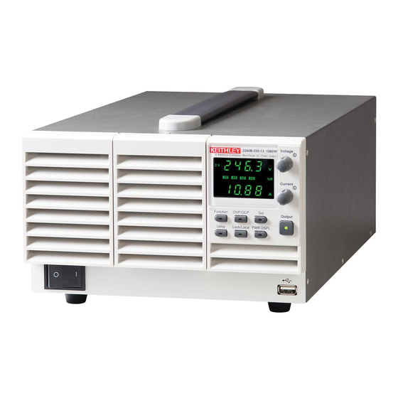
2260B Series Programming Manual Appearance 2260B Front Panel 2260B-30-72, 80-27, 250-9, 800-2 (720W) Voltage Display knob Current knob Cover panel Output Power Function switch keys USB A port 2260B-30-108, 80-40, 250-13, 800-4 (1080W) 2260B-30-36, 80-13, 250-4, 800-1 (360W) 2260B-30-108 1080W... - Page 14 GETTING STARTED The Function keys along with the Output key will Function Keys light up when a key is active. The Function key is used to configure the power supply. Set the overcurrent or overvoltage protection levels. Sets the current and voltage limits. Used to run customized Test sequence for testing.
- Page 15 2260B Series Programming Manual Sets the voltage. Voltage Knob Sets the current. Current Knob Press to turn on the output. The Output Output key will light up when the output is active. The USB A port is used to update the firmware.
-
Page 16: Rear Panel
GETTING STARTED Rear Panel 2260B-30-72, 80-27 (720W) Sense+ USB B Output Analog control terminal port terminal connector Chassis ground Sense- SER.NO. LABEL terminal Output terminal (-) 240V 47 63Hz 1000VA MAX. AC Input 2260B-30-108, 80-40 (1080W) 2260B-30-36, 80-13 (360W) AC Input SER.NO. - Page 17 2260B Series Programming Manual 2260B-250-9, 800-2 (720W) Sense+ USB B Output Analog control terminal port terminals +V connector Sense- terminal SN.C. S SER.NO. LABEL Chassis ground Output terminals -V 240V 47 63Hz 1000VA MAX. AC Input 2260B-250-4, 800-1 2260B-250-13, 800-4 (1080W) (360W) AC Input SN.C.
- Page 18 GETTING STARTED Standard 26 pin MIL connector Analog Control (OMRON XG4 IDC plug). Connector The analog control connector is used to monitor current and voltage output, machine status (OVP, OCP, OTP etc.), and for analog control of the current and voltage output. Use an OMRON XG5 IDC socket as the mating socket.
- Page 19 2260B Series Programming Manual The USB B port is used for remote USB B port control. Temperature controlled fans Fans The Ethernet port is used for remote Ethernet Port control and digital monitoring from a PC. 360W models: Line Voltage 2260B-30-36/80-13/250-4/ 800-1 Input 720W models:...
-
Page 20: Configuration Settings
GETTING STARTED Configuration Settings Setting Configuration Settings The normal configuration settings (F-01~F-61, Background F-88, F-89) are used to configure or view system settings. Use the following operation steps when configuring the interface settings used in the Remote Control chapter on page 23. Ensure the load is not connected. -
Page 21: Configuration Table
2260B Series Programming Manual 4. Use the Current knob to set the Current parameter for the chosen F setting. 5. Press the Voltage knob to save the Voltage configuration setting. Conf will be displayed when successful. Press the Function key again to exit Exit the configuration settings. - Page 22 GETTING STARTED 0.01A/s~72.00A/s (2260B-30-36) 0.1A/s~144.0A/s (2260B-30-72) 0.1A/s~216.0A/s (2260B-30-108) 0.01A/s~27.00A/s (2260B-80-13) 0.01A/s~54.00A/s (2260B-80-27) 0.01A/s~81.00A/s (2260B-80-40) Rising current slew rate F-06 0.001A/s~9.000A/s (2260B-250-4) 0.01A/s~18.00A/s (2260B-250-9) 0.01A/s~27.00A/s (2260B-250-13) 0.001A/s~2.880A/s (2260B-800-1) 0.001A/s~5.760A/s (2260B-800-2) 0.001A/s~8.640A/s (2260B-800-4) 0.01A/s~72.00A/s (2260B-30-36) 0.1A/s~144.0A/s (2260B-30-72) 0.1A/s~216.0A/s (2260B-30-108) 0.01A/s~27.00A/s (2260B-80-13) 0.01A/s~54.00A/s (2260B-80-27) 0.01A/s~81.00A/s (2260B-80-40) Falling current slew rate F-07...
- Page 23 2260B Series Programming Manual 0 = Panel lock: allow output off Lock Mode F-19 1 = Panel lock: allow output on/off USB/GPIB settings Front panel USB State F-20 0 = Absent, 1 = Mass Storage 0 = Absent, 2 = USB-CDC, 3 = GPIB- Rear panel USB State F-21 USB adapter...
- Page 24 GETTING STARTED System Settings 0 = Disable Factory Set Value F-88 1 = Return to factory settings 0, 1 = 2260B version 2, 3 = 2260B build year 4, 5 = 2260B build month/day 6, 7 = Keyboard CPLD version Show Version F-89 8, 9 = Analog-Control CPLD version...
- Page 25 2260B Series Programming Manual Power On and Calibration settings can only be set *Note during power up.
-
Page 26: Remote Control
REMOTE CONTROL EMOTE CONTROL This chapter describes basic configuration of IEEE488.2 based remote control. Interface Configuration ..........24 USB Remote Interface ..............24 Configure GPIB Interface ............... 24 Configure Ethernet Connection............. 26 Web Server Configuration ............... 26 Sockets Server Configuration ............27 USB Function Check................ -
Page 27: Interface Configuration
2260B Series Programming Manual Interface Configuration USB Remote Interface Type A, host PC side connector configuration Rear panel Type B, slave 2260B side connector 1.1/2.0 (full speed/high speed) Speed CDC (communications device USB Class class) 1. Connect the USB cable to the rear Panel operation panel USB B port. - Page 28 REMOTE CONTROL 3. Connect a GPIB cable from a GPIB controller to the GPIB port on the adapter. Type A plug From computer From Type B plug on Power supply GPIB to USB adapter 4. Turn the 2260B on. 5. Press the Function key to enter the Page 7 Normal configuration settings.
-
Page 29: Configure Ethernet Connection
2260B Series Programming Manual Configure Ethernet Connection The Ethernet interface can be configured for a number of different applications. Ethernet can be configured for basic remote control or monitoring using a web server or it can be configured as a socket server. -
Page 30: Sockets Server Configuration
REMOTE CONTROL 2. Press the Function key to enter the Page 7 Normal configuration settings. Set the following LAN settings: F-36 = 1 Enable LAN F-37 = 1 Turn DHCP to enable F-59 = 1 Turn the web server on It may be necessary to cycle the power or refresh Note the web browser to connect to a network. -
Page 31: Usb Function Check
2260B Series Programming Manual F-45 = 128 Subnet Mask part 3 of 4 F-46 = 0 Subnet Mask part 4 of 4 F-43 = 172 Gateway part 1 of 4 F-44 = 16 Gateway part 2 of 4 F-45 = 21 Gateway part 3 of 4 F-46 = 101 Gateway part 4 of 4... - Page 32 REMOTE CONTROL 2. From the Configuration panel access; My System>Devices and Interfaces 3. Select "COM7". 4. Press Open VISA Test Panel. The displayed COM port No. may differ with the Note...
- Page 33 2260B Series Programming Manual picture shown here. It depends on the virtual COM port number in your system. Here "COM7" is the Virtual COM port assigned to the 2260B. 5. Click the Configuration icon. 6. In the I/O Settings tab, select the Enable Termination Character check box.
-
Page 34: Web Server Remote Control Function Check
REMOTE CONTROL Web Server Remote Control Function Check Enter the IP address of the power supply in a Functionality web browser after the instrument has been check configured as a web server http:// XXX.XXX.XXX.XXX The web browser interface appears. Socket Server Function Check To test the socket server functionality, National Background Instruments Measurement and Automation... - Page 35 2260B Series Programming Manual Firmware: V1.12 or above Requirements Operating System: Windows XP, 7 1. Start the NI Measurement and Automation Functionality Explorer (MAX) program. Using Windows, check press: Start>All Programs>National Instruments>Measurement & Automation 2. From the Configuration panel access; My System>Devices and Interfaces>Network Devices 3.
- Page 36 REMOTE CONTROL 5. Select Manual Entry of Raw Socket from the popup window. 6. Click Next. 7. Enter the IP address and the port number of the 2260B. The port number is fixed at 2268. 8. Click the Validate button. A popup box will appear when successful.
- Page 37 2260B Series Programming Manual 10. Next configure the Alias (name) of the 2260B connection. In this example the Alias is: PS_DC1 11. Click finish.
- Page 38 REMOTE CONTROL 12. The IP address of the 2260B will now appear under Network Devices in the configuration panel. Select this icon now. 13. Press Open VISA Test Panel. 14. Click Configuration icon. 15. In the I/O Settings tab, select the Enable Termination Character check box.
- Page 39 2260B Series Programming Manual 17. Click the Input/Output icon. 18. Ensure *IDN?\n is selected in the Select or Enter Command dropdown text box. 19. Click the Query button. 20. The *IDN? query should be returned to the buffer area.
-
Page 40: Socket Server Examples
REMOTE CONTROL Socket Server Examples Visual Basic Example The following visual basic programming Background example uses the VISA COM 3.0 Type Library. The example will connect to the 2260B using the IP address of 172.15.5.133 over port 2268. The program will send the *IDN? query to the 2260B, print the return string and then close the connection. -
Page 41: C++ Example
2260B Series Programming Manual C++ Example The following program creates a connection to Background the 2260B and sets the voltage to 3.3 volts and the current 1.5 amps. The voltage and current reading is then read back and the connection is closed. - Page 42 REMOTE CONTROL...
-
Page 43: Labview Example
2260B Series Programming Manual LabVIEW Example The following picture shows a LabView Background programming example for the 2260B. -
Page 44: Command Syntax
REMOTE CONTROL Command Syntax Partial compatibility IEEE488.2 Compatible Partial compatibility Standard SCPI, 1999 SCPI commands follow a tree-like structure, Command organized into nodes. Each level of the Structure command tree is a node. Each keyword in a SCPI command represents each node in the command tree. - Page 45 2260B Series Programming Manual A query is a simple or Query compound command followed by a question mark (?). A parameter (data) is returned. meas:curr:dc? Example Two or more commands on Compound the same command line. Compound commands are separated with either a semi- colon (;) or a semi-colon and a colon (;:).
- Page 46 REMOTE CONTROL Commands and queries have two different Command Forms forms, long and short. The command syntax is written with the short form of the command in capitals and the remainder (long form) in lower case. The commands can be written in capitals or lower-case, just so long as the short or long forms are complete.
- Page 47 2260B Series Programming Manual integers 0, 1, 2, 3 <NR1> decimal 0.1, 3.14, 8.5 <NR2> numbers floating point 4.5e-1, 8.25e+1 <NR3> any of NR1, 2, 3 1, 1.5, 4.5e-1 <NRf> String parameters are any ASCII <string> characters (ASCII: 20H to 7EH) that are enclosed in either single or double quotes.
-
Page 48: Command List
REMOTE CONTROL Command List Abort Commands ABORt ..................48 Apply Commands APPLy ..................48 DISPlay:MENU[:NAME] ............. 49 Display DISPlay[:WINDow]:TEXT:CLEar ........50 Commands DISPlay[:WINDow]:TEXT[:DATA] ........50 DISPlay:BLINk ............... 51 INITiate[:IMMediate]:NAME ..........51 Initiate Commands MEASure[:SCALar]:CURRent[:DC] ........52 Measure MEASure[:SCALar]:VOLTage[:DC] ........52 Commands MEASure[:SCALar]:POWer[:DC] ........ - Page 49 2260B Series Programming Manual [SOURce:]CURRent[:LEVel][:IMMediate][:AMPLitude] 61 Source [SOURce:]CURRent[:LEVel]:TRIGgered[:AMPLitude] . 62 Commands [SOURce:]CURRent:PROTection[:LEVel] ......62 [SOURce:]CURRent:PROTection:STATe ......63 [SOURce:]CURRent:SLEW:RISing ........63 [SOURce:]CURRent:SLEW:FALLing......... 64 [SOURce:]RESistance[:LEVel][:IMMediate][:AMPLitude] ....................64 [SOURce:]VOLTage[:LEVel][:IMMediate][:AMPLitude] ....................65 [SOURce:]VOLTage[:LEVel]:TRIGgered[:AMPLitude] . 65 [SOURce:]VOLTage:PROTection[:LEVel] ....... 66 [SOURce:]VOLTage:SLEW:RISing ........66 [SOURce:]VOLTage:SLEW:FALLing ........ 67 TRIGger:TRANsient[:IMMediate] ........
- Page 50 REMOTE CONTROL SYSTem:KEYLock:MODE ..........80 SYSTem:KLOCk ..............81 SYSTem:INFormation ............81 SYSTem:PRESet ..............82 SYSTem:VERSion ..............82 *CLS ..................83 Common *ESE ..................83 Commands *ESR ..................84 *IDN ..................84 *OPC ..................84 *RST ..................85 *SRE ..................85 *STB ..................
-
Page 51: Abort Commands Abort
2260B Series Programming Manual Abort Commands ABORt ..................48 ABORt The ABORt command will cancel any triggered Description actions. Syntax ABORt APPLy Commands APPLy ..................48 APPLy Query The APPLy command is used to set both the Description voltage and current. The voltage and current will be output as soon as the function is executed if the programmed values are within the accepted range. -
Page 52: Display Display:menu[:Name]
REMOTE CONTROL <NRf> 0% ~ 105% of the rated output Parameter <voltage> voltage. <NRf> 0% ~ 105% of the rated output <current> current. 0 volts/0 amps Maxium value for the present range. Return parameter <NRf> Returns the voltage and current. Example APPL 5.05,1.1 Sets the voltage and current to 5.05V and 1.1A. -
Page 53: Display[:Window]:Text[:Data]
2260B Series Programming Manual Example DISP:MENU:NAME 0 Sets the display to the Voltage/Current display screen. DISPlay[:WINDow]:TEXT:CLEar Clears the text on the main screen from the Description DISPlay[:WINDow]:TEXT[:DATA] command . Syntax DISPlay[:WINDow]:TEXT:CLEar DISPlay[:WINDow]:TEXT[:DATA] Query Sets or queries the data text that will be written to Description the display. -
Page 54: Display:blink
REMOTE CONTROL DISPlay:BLINk Query Turns blink on or off for the display. Description Syntax DISPlay:BLINk { 0 | 1 | OFF | ON } Query Syntax DISPlay:BLINk? <NR1>Turns blink OFF Parameter Turns blink OFF <NR1> Turns blink ON Turns blink ON <NR1>Turns blink OFF Return parameter 0 <NR1>Turns blink ON... -
Page 55: Measure Measure[:Scalar]:Current[:Dc]
2260B Series Programming Manual Measure Commands MEASure[:SCALar]:CURRent[:DC] ........52 MEASure[:SCALar]:VOLTage[:DC] ........52 MEASure[:SCALar]:POWer[:DC] ........52 MEASure[:SCALar]:CURRent[:DC] Query Takes a measurement and returns the average Description output current Syntax MEASure[:SCALar]:CURRent[:DC]? Returns the current in amps. Return parameter <NRf> MEASure[:SCALar]:VOLTage[:DC] Query Takes a measurement and returns the average Description output voltage. -
Page 56: Output Commands
REMOTE CONTROL Output Commands OUTPut:DELay:ON .............. 53 OUTPut:DELay:OFF ............53 OUTPut:MODE ..............54 OUTPut[:STATe][:IMMediate] ..........54 OUTPut[:STATe]:TRIGgered ..........54 OUTPut:PROTection:CLEar ..........55 OUTPut:PROTection:TRIPped .......... 55 OUTPut:DELay:ON Query Sets the Delay Time in seconds for turning the Description output on. The delay is set to 0.000 by default. Syntax OUTPut:DELay:ON <NRf>... -
Page 57: Output:mode
2260B Series Programming Manual OUTPut:MODE Query Sets the 2260B output mode. This is the equivalent Description to the F-03 (V-I Mode Slew Rate Select) settings. Syntax OUTPut:MODE {<NR1>|CVHS|CCHS|CVLS|CCLS} Return Syntax OUTPut:MODE? CV high speed priority Parameter CV high speed priority CVHS CC high speed priority CC high speed priority... -
Page 58: Output:protection:clear
REMOTE CONTROL <NR1>Turns the output off when a software Parameter trigger is generated. Turns the output off when a software trigger is generated. <NR1>Turns the output on when a software trigger is generated. Turns the output on when a software trigger is generated. -
Page 59: Sense Sense:average:count
2260B Series Programming Manual Sense Commands SENSe:AVERage:COUNt ............ 56 SENSe:AVERage:COUNt Query Determines the level of smoothing for the average Description setting. This is the equivalent to the F-17 function setting. Syntax SENSe:AVERage:COUNt {<NR1>| LOW | MIDDle | HIGH} Query Syntax SENSe:AVERage:COUNt? Low level of smoothing. -
Page 60: Status Status:operation[:Event]
REMOTE CONTROL Status Commands STATus:OPERation[:EVENt] ..........57 STATus:OPERation:CONDition ........57 STATus:OPERation:ENABle ..........57 STATus:OPERation:PTRansition ........58 STATus:OPERation:NTRansition ........58 STATus:QUEStionable[:EVENt] ........58 STATus:QUEStionable:CONDition........59 STATus:QUEStionable:ENABle ......... 59 STATus:QUEStionable:PTRansition ........59 STATus:QUEStionable:NTRansition ......... 59 STATus:PRESet ..............60 STATus:OPERation[:EVENt] Query Queries the Operation Status Event register and Description clears the contents of the register. -
Page 61: Status:operation:ptransition
2260B Series Programming Manual 0~32767 Parameter <NRf> 0~32767 Return parameter <NR1> STATus:OPERation:PTRansition Query Sets or queries the bit sum of the positive Description transition filter of the Operation Status register. Syntax STATus:OPERation:PTRansition <NRf> STATus:OPERation:PTRansition? 0~32767 Parameter <NRf> 0~32767 Return parameter <NR1> STATus:OPERation:NTRansition Query Sets or queries the bit sum of the negative... -
Page 62: Status:questionable:condition
REMOTE CONTROL STATus:QUEStionable:CONDition Query Queries the status (bit sum) of the Questionable Description Status register. This query will not clear the register. Query Syntax STATus:QUEStionable:CONDition? 0~32767 Parameter <NRf> 0~32767 Return parameter <NR1> STATus:QUEStionable:ENABle Query Sets or queries the bit sum of the Questionable Description Status Enable register. -
Page 63: Status:preset
2260B Series Programming Manual 0~32767 Parameter <NRf> 0~32767 Return parameter <NR1> STATus:PRESet This command resets the ENABle register, the Description PTRansistion filter and NTRansistion filter on the Operation Status and Questionable Status Registers. The registers/filters will be reset to a default value. -
Page 64: [Source:]Current[:Level][:Immediate][:Amplitude]
REMOTE CONTROL Source Commands [SOURce:]CURRent[:LEVel][:IMMediate][:AMPLitude] ....................61 [SOURce:]CURRent[:LEVel]:TRIGgered[:AMPLitude] ....................62 [SOURce:]CURRent:PROTection[:LEVel] ......62 [SOURce:]CURRent:PROTection:STATe ......63 [SOURce:]CURRent:SLEW:RISing ........63 [SOURce:]CURRent:SLEW:FALLing ........ 64 [SOURce:]RESistance[:LEVel][:IMMediate] [:AMPLitude] ................64 [SOURce:]VOLTage[:LEVel][:IMMediate][:AMPLitude] ....................65 [SOURce:]VOLTage[:LEVel]:TRIGgered[:AMPLitude] ....................65 [SOURce:]VOLTage:PROTection[:LEVel] ....... 66 [SOURce:]VOLTage:SLEW:RISing ........66 [SOURce:]VOLTage:SLEW:FALLing ........ 67 [SOURce:]CURRent[:LEVel][:IMMediate] [:AMPLitude] Query... -
Page 65: [Source:]Current[:Level]:Triggered[:Amplitude]
2260B Series Programming Manual [SOURce:]CURRent[:LEVel]:TRIGgered [:AMPLitude] Query Sets or queries the current level in amps when a Description software trigger has been generated. Syntax [SOURce:]CURRent[:LEVel]:TRIGgered[:AMPLitude] {<NRf>|MIN|MAX} Query Syntax [SOURce:]CURRent[:LEVel]:TRIGgered[:AMPLitude]? [MIN|MAX] 0%~105% of the rated current output in amps. Parameter/Return <NRf> Minimum current level. -
Page 66: [Source:]Current:protection:state
REMOTE CONTROL [SOURce:]CURRent:PROTection:STATe Query Turns OCP (over-current protection) on or off. Description Syntax [SOURce:]CURRent:PROTection:STATe {0|1|OFF|ON} Query Syntax [SOURce:]CURRent:PROTection:STATe? <NR1> Turns the buzzer off. Parameter/Return 0 Turns the buzzer off. <NR1> Turns the buzzer on. Turns the buzzer on. Returns bleeder resistor status (0 or 1). Return parameter <Bool>... -
Page 67: [Source:]Current:slew:falling
2260B Series Programming Manual [SOURce:]CURRent:SLEW:FALLing Query Sets or queries the falling current slew rate. This is Description only applicable for CC slew rate priority mode. Syntax [SOURce:]CURRent:SLEW:FALLing {<NRf>|MIN|MAX} Query Syntax [SOURce:]CURRent:SLEW:FALLing? [MIN|MAX] 0.01A/s~72.00A/s (2260B-30-36) Parameter/Return NRf 0.1A/s~144.0A/s (2260B-30-72) 0.1A/s~216.0A/s (2260B-30-108) 0.01A/s~27.00A/s (2260B-80-13) 0.01A/s~54.00A/s (2260B-80-27) 0.01A/s~81.00A/s (2260B-80-40) -
Page 68: [Source:]Voltage[:Level][:Immediate][:Amplitude]
REMOTE CONTROL <NRf> Resistance in ohms: Parameter/Return 0.000Ω~0.833Ω (2260B-30-36) 0.000Ω~0.417Ω (2260B-30-72) 0.000Ω~0.278Ω (2260B-30-108) 0.000Ω~5.926Ω (2260B-80-13) 0.000Ω~2.963Ω (2260B-80-27) 0.000Ω~1.975Ω (2260B-80-40) 0.00Ω~ 55.55Ω (2260B-250-4) 0.00Ω~ 27.77Ω (2260B-250-9) 0.00Ω~ 18.51Ω (2260B-250-13) 0.0Ω~ 555.5Ω (2260B-800-1) 0.0Ω~ 277.8Ω (2260B-800-2) 0.0Ω~ 185.1Ω (2260B-800-4) Minimum internal resistance in ohms Maximum internal resistance in ohms Example SOUR:RES:LEV:IMM:AMPL 0.1... -
Page 69: [Source:]Voltage:protection[:Level]
2260B Series Programming Manual Syntax [SOURce:]VOLTage[:LEVel]:TRIGgered[:AMPLitude] {<NRf>|MIN|MAX} Query Syntax [SOURce:]VOLTage[:LEVel]:TRIGgered[:AMPLitude]? [MIN|MAX] 0%~105% of the rated voltage output in volts. Parameter/Return <NRf> Minimum current level. Maximum current level. Example SOUR:VOLT:LEV:TRIG:AMPL 10 Sets the voltage level to 10 volts when a software trigger is generated. -
Page 70: [Source:]Voltage:slew:falling
REMOTE CONTROL Example SOUR:VOLT:SLEW:RIS MAX Sets the rising voltage slew rate to its maximum. [SOURce:]VOLTage:SLEW:FALLing Query Sets or queries the falling voltage slew rate. This is Description only applicable for CV slew rate priority mode. Syntax [SOURce:]VOLTage:SLEW:FALLing {<NRf>|MIN|MAX} Query Syntax [SOURce:]VOLTage:SLEW:FALLing? [MIN|MAX] 0.01V/s~60V/s (2260B-30-XX) Parameter/Return <NRf>... - Page 71 2260B Series Programming Manual Trigger Commands The trigger commands generate and configure software triggers. This power supply supports the following two trigger functions. • TRANsient Specifies the current and voltage settings in advance and uses the trigger to set them. Please refer to VOLT:TRIG, CURR:TRIG on page 62 and 69 for details.
- Page 72 REMOTE CONTROL Example: TRIG:TRAN:SOUR IMM Immediate Mode CURR:TRIG MAX VOLT:TRIG 5 INIT:NAME TRAN The current changes to the maximum, and the voltage changes to 5V. Example: TRIG:TRAN:SOUR BUS Bus Mode CURR:TRIG MAX VOLT:TRIG 5 INIT:NAME TRAN TRIG:TRAN The current changes to the maximum, and the voltage changes to 5V.
- Page 73 2260B Series Programming Manual Example: TRIG:OUTP:SOUR IMM Immediate Mode OUTP:TRIG 1 INIT:NAME OUTP The output changes to ON. Example: TRIG:OUTP:SOUR BUS Bus Mode OUTP:TRIG 1 INIT:NAME OUTP TRIG:OUTP The output changes to ON.
-
Page 74: System:configure:beeper[:State]
REMOTE CONTROL System Function Command SYSTem:CONFigure:BEEPer[:STATe] ......71 SYSTem:CONFigure:BLEeder[:STATe] ......72 SYSTem:CONFigure:BTRip[:IMMediate] ......72 SYSTem:CONFigure:BTRip:PROTection......72 SYSTem:CONFigure:CURRent:CONTrol ......73 SYSTem:CONFigure:VOLTage:CONTrol ....... 73 SYSTem:CONFigure:MSLave ..........74 SYSTem:CONFigure:OUTPut:EXTernal[:MODE] ..74 SYSTem:CONFigure:OUTPut:PON[:STATe] ....75 SYSTem:COMMunicate:ENABle ........75 SYSTem:COMMunicate:GPIB[:SELF]:ADDRess ... 76 SYSTem:COMMunicate:LAN:IPADdress......77 SYSTem:COMMunicate:LAN:GATEway ......77 SYSTem:COMMunicate:LAN:SMASk ....... -
Page 75: System:configure:bleeder[:State]
2260B Series Programming Manual <NR1> Turns the buzzer off. Parameter Turns the buzzer off. <NR1> Turns the buzzer on. Turns the buzzer on. Returns the buzzer status. Return parameter <Boolean> SYSTem:CONFigure:BLEeder[:STATe] Query Sets or queries the status of the bleeder resistor. Description Syntax SYSTem:CONFigure:BLEeder[:STATe]... -
Page 76: System:configure:current:control
REMOTE CONTROL Syntax SYSTem:CONFigure:BTRip:PROTection {DISable|ENABle|0|1} Query Syntax SYSTem:CONFigure:BTRip:PROTection? <NR1> Enables the power switch trip for Parameter OVP or OCP. Enables the power switch trip for OVP or ENABle OCP. <NR1> Disables the power switch trip for OVP or OCP. Disables the power switch trip for OVP or DISable OCP. -
Page 77: System:configure:mslave
2260B Series Programming Manual Description Parameter/Return <NR1> Local (Panel) control External voltage control External resistance control; 10kΩ = Vo max, 0kΩ = Vo min. External resistance control; 10kΩ = Vo min, 0kΩ = Vo max. SYSTem:CONFigure:MSLave Query Sets or queries the unit operation mode. This Description setting is only applied after the power has been cycled. -
Page 78: System:configure:output:pon[:State]
REMOTE CONTROL Active high Parameter Active high HIGH Active low Active low <boolean>Active high Return Parameter 0 <boolean>Active low SYSTem:CONFigure:OUTPut:PON[:STATe] Query Sets the unit to turn the output ON/OFF at power- Description up. This setting is only applied after the power has been cycled. -
Page 79: System:communicate:gpib[:Self]:Address
2260B Series Programming Manual Parameter <mode> Turns the selected mode off. Turns the selected mode off. Turns the selected mode on. (Auto detect speed in USB) Turns the selected mode on. (Auto detect speed in USB) Full Speed (USB Only) FULL Full Speed (USB Only) <interface>... -
Page 80: System:communicate:lan:ipaddress
REMOTE CONTROL Example SYST:COMM:GPIB:SELF:ADDR 15 Sets the GPIB address to 15. SYSTem:COMMunicate:LAN:IPADdress Query Sets or queries LAN IP address. This setting is only Description applied after the power has been cycled. Syntax SYSTem:COMMunicate:LAN:IPADdress <string> Query Syntax SYSTem:COMMunicate:LAN:IPADdress? LAN IP address in string format ( “address”) Parameter/Return <string>... -
Page 81: System:communicate:lan:mac
2260B Series Programming Manual SYSTem:COMMunicate:LAN:MAC Query Returns the unit MAC address as a string. The Description MAC address cannot be changed. Query Syntax SYSTem:COMMunicate:LAN:MAC? Returns the MAC address in the following Return parameter <string> format “FF-FF-FF-FF-FF-FF” Example SYST:COMM:LAN:MAC? 02-80-AD-20-31-B1 Returns the MAC address. SYSTem:COMMunicate:LAN:DHCP Query Turns DHCP on/off. -
Page 82: System:communicate:lan:hostname
REMOTE CONTROL SYSTem:COMMunicate:LAN:HOSTname Query Queries the host name. Description Query Syntax SYSTem:COMMunicate:LAN:HOSTname? Host name in string format Return Parameter <string> Query Example SYST:COMM:LAN:HOST? P-160054 Returns the host name (P-160054). SYSTem:COMMunicate:LAN:WEB:PACTive Query Sets or queries whether the web password is on or Description off. -
Page 83: System:communicate:usb:front:state
2260B Series Programming Manual SYSTem:COMMunicate:USB:FRONt:STATe Query Queries the front panel USB-A port state. Description Query Syntax SYSTem:COMMunicate:USB:FRONt:STATe? <NR1>Absent Return parameter 0 <NR1>Mass Storage SYSTem:COMMunicate:USB:REAR:STATe Query Queries the rear panel USB-B port state. Description Query Syntax SYSTem:COMMunicate:USB:REAR:STATe? <NR1>Absent Return parameter 0 <NR1>USB-CDC <NR1>GPIB-USB SYSTem:ERRor... -
Page 84: System:klock
REMOTE CONTROL Panel lock: allow output off. Parameter / Panel lock: allow output on/off. Return parameter SYSTem:KLOCk Query Enables or disables the front panel key lock. Description Syntax SYSTem:KLOCk { OFF | ON | 0 | 1} Query Syntax SYSTem:KLOCk? Panel keys unlocked Parameter Panel keys unlocked... -
Page 85: System:preset
2260B Series Programming Manual SYSTem:PRESet Resets all the settings to the factory default Description settings. See page 107 for details. This command is identical in effect to the *RST command. Syntax SYSTem:PRESet SYSTem:VERSion Query Returns the version of the SCPI specifications that Description the unit complies with. -
Page 86: Cls
REMOTE CONTROL IEEE 488.2 Common Commands *CLS ..................83 *ESE ..................83 *ESR ..................84 *IDN ..................84 *OPC ..................84 *RST ..................85 *SRE ..................85 *STB ..................85 *TRG ..................86 *TST ..................86 *WAI ..................86 *CLS The *CLS command clears the Standard Event Description Status, Operation Status and Questionable Status... -
Page 87: Esr
2260B Series Programming Manual *ESR Query Queries the Standard Event Status (Event) register. Description The Event Status register is cleared after it is read. Query Syntax *ESR? Returns the bit sum of the Standard Event Return parameter <NR1> Status (Event) register and clears the register. *IDN Query Queries the manufacturer, model name, serial... -
Page 88: Rst
REMOTE CONTROL *RST Resets all the settings to the factory default Description settings. See page 107 for details. This command is identical in effect to the SYSTem:PRESet command. Syntax *RST *SRE Query Sets or queries the Service Request Enable register. Description The Service Request Enable register determines which registers of the Status Byte register are able... -
Page 89: Trg
2260B Series Programming Manual *TRG The *TRG command is able to generate a “get” Description (Group Execute Trigger). If the 2260B cannot accept a trigger at the time of the command, an error message is generated (-211, “Trigger ignored”). Syntax *TRG *TST Query... -
Page 90: Status Register Overview
REMOTE CONTROL Status Register Overview To program the 2260B power supply effectively, the Status registers need to be understood. This chapter explains in detail how the Status registers are used and how to configure them. Introduction to the Status Registers The status registers are used to determine the Overview status of the power supply. -
Page 91: The Status Registers
2260B Series Programming Manual The Status Registers Questionable Status Register Condition PTR/NTP Event Enable OV (Over-Voltage) OC (Over-Current) Not Used POW (AC Power Off) Output OT (Over-Temperature) Buffer Not Used Not Used Not Used VL (Voltage-Limit) CL (Current-Limit) Not Used Error Que SD (Shutdown Alarm) Power-Limit... -
Page 92: Questionable Status Register Group
REMOTE CONTROL Questionable Status Register Group The Questionable Status Register Group Overview indicates if any protection modes or limits have been tripped. Questionable Status Register Condition PTR/NTP Event Enable & & & Not Used & & & Not Used & Not Used &... - Page 93 2260B Series Programming Manual OT (Over Temperature) Over temperature protection has been tripped VL (Voltage Limit) Voltage limit has been reached CL (Current Limit) Current limit has been reached SD (Shutdown Alarm) 2048 PL (Power-Limit) 4096 The Questionable Status Condition Register Condition Register indicates the status of the power supply.
-
Page 94: Operation Status Register Group
REMOTE CONTROL Operation Status Register Group The Operation Status Register Group indicates Overview the operating status of the power supply. Operation Status Register Condition PTR/NTP Event Enable & & Not Used & Not Used & Not Used & Not Used &... - Page 95 2260B Series Programming Manual CV (Constant voltage mode) Indicates if the 2260B is in CV mode. CC (Constant current mode) 1024 Indicates if the 2260B is in CC mode. OND (Output ON Delay) 2048 Indicates if Output ON delay time is active OFD (Output OFF Delay) 4096...
-
Page 96: Standard Event Status Register Group
REMOTE CONTROL The Enable register determines which Enable Register registered Events in the Event Register will be used to set the OPER bit in the Status Byte Register. Standard Event Status Register Group The Standard Event Status Register Group Overview indicates if any errors have occurred. - Page 97 2260B Series Programming Manual QUE (Query Error) The Query Error bit is set in response to an error reading the Output Queue. This can be caused by trying to read the Output Queue when there is no data present. DDE (Device Dependent Error) Device specific error.
-
Page 98: Status Byte Register & Service Request Enable Register
REMOTE CONTROL Status Byte Register & Service Request Enable Register The Status Byte register consolidates the status Overview events of all the status registers. The Status Byte register can be read with the *STB? query and can be cleared with the *CLS command. Output Buffer Error Que... - Page 99 2260B Series Programming Manual (ESB) Event Summary Bit. The ESB is the summary bit for the Standard Event Status Register group. MSS Bit The MSS Bit is the summary of the Status Byte Register and Service Request register (bits 1-5, 7).
-
Page 100: Error List
REMOTE CONTROL Error List Command Errors Overview An <error/event number> in the range [ -199 , - 100 ] indicates that an IEEE 488.2 syntax error has been detected by the instrument’s parser. The occurrence of any error in this class shall cause the command error bit (bit 5) in the event status register (IEEE 488.2, section 11.5.1) to be set. - Page 101 2260B Series Programming Manual Error Code Description This is the generic syntax error for devices that -100 Command cannot detect more specific errors. This code Error indicates only that a Command Error as defined in IEEE 488.2,11.5.1.1.4 has occurred. An unrecognized command or data type was -102 Syntax error encountered;...
- Page 102 REMOTE CONTROL The header contains more that twelve -112 Program characters (see IEEE 488.2, 7.6.1.4.1). mnemonic too long The header is syntactically correct, but it is -113 Undefined header undefined for this specific device; for example, *XYZ is not defined for any device. The value of a numeric suffix attached to a -114 Header suffix out of range...
- Page 103 2260B Series Programming Manual Either the character data element contains an -141 Invalid invalid character or the particular element character data received is not valid for the header. A legal character data element was encountered -148 Character where prohibited by the device. data not allowed A string data element was expected, but was -151 Invalid string...
-
Page 104: Execution Errors
REMOTE CONTROL Execution Errors Overview An <error/event number> in the range [ -299 , - 200 ] indicates that an error has been detected by the instrument’s execution control block. The occurrence of any error in this class shall cause the execution error bit (bit 4) in the event status register (IEEE 488.2, section 11.5.1) to be set. - Page 105 2260B Series Programming Manual Indicates that a command is not executable -201 Invalid while while the device is in local due to a hard local in local control (see IEEE 488.2, 5.6.1.5); for example, a device with a rotary switch receives a message which would change the switches state, but the device is in local so the message can not be executed.
-
Page 106: Device Specific Errors
REMOTE CONTROL Indicates that a legal program data element was -222 Data out of parsed but could not be executed because the range interpreted value was outside the legal range as defined by the device (see IEEE 488.2, 11.5.1.1.5.). Used where exact value, from a list of possible -224 Illegal values, was expected. -
Page 107: Query Errors
2260B Series Programming Manual or query errors; see the other error definitions in this section. Error Code Description Indicates that some error, termed “system -310 System error error” by the device, has occurred. This code is device-dependent. Indicates that the firmware detected a fault -320 Storage fault when using data storage. - Page 108 REMOTE CONTROL Error Code Description This is the generic query error for devices that -400 Query error cannot detect more specific errors. This code indicates only that a Query Error as defined in IEEE 488.2, 11.5.1.1.7 and 6.3 has occurred.
-
Page 109: Appendix
2260B Series Programming Manual PPENDIX 2260B Default Settings ........... 107 Error Messages & Messages ........109 LED Display Format ..........110... -
Page 110: 2260B Default Settings
APPENDIX 2260B Default Settings The following default settings are the factory configuration settings for the power supply. Default Setting Initial Settings Output LOCK 0 (Disabled) Voltage Current Maximum Maximum Normal Function Settings Setting Default Setting Output ON delay time F-01 0.00s Output OFF delay time F-02... - Page 111 2260B Series Programming Manual Falling current slew rate F-07 72.00A/s (2260B-30-36) 144.0A/s (2260B-30-72) 216.0A/s (2260B-30-108) 27.00A/s (2260B-80-13) 54.00A/s (2260B-80-27) 81.00A/s (2260B-80-40) 9.000A/s (2260B-250-4) 18.00A/s (2260B-250-9) 27.00A/s (2260B-250-13) 2.880A/s (2260B-800-1) 5.760A/s (2260B-800-2) 8.640A/s (2260B-800-4) Internal resistance setting F-08 0.000 Ω Bleeder circuit control F-09 1 = ON Buzzer ON/OFF control...
-
Page 112: Error Messages & Messages
APPENDIX Error Messages & Messages The following error messages or messages may appear on the 2260B screen during operation. Error Messages Description Err 001 USB Mass Storage is not present Err 002 No (such)file in USB mass storage Err 003 Empty memory location Err 004 File access error... -
Page 113: Led Display Format
2260B Series Programming Manual LED Display Format Use the following table to read the LED display messages. -
Page 114: Index
INDEX NDEX Caution symbol ......2 List of features ......8 Cleaning the instrument ..... 4 Messages ........109 Configuration Model differences ......7 table ..........18 Power on/off Connector plug manufacturer .. 15 safety instruction ......16 DECA SwitchLab ....... 15 Rear panel diagram .... - Page 115 Specifications are subject to change without notice. All Keithley trademarks and trade names are the property of Keithley Instruments, Inc. All other trademarks and trade names are the property of their respective companies. A Greater Measure of Confidence A Tektronix Company 08/15...
Need help?
Do you have a question about the Keithley 2260B Series and is the answer not in the manual?
Questions and answers