Table of Contents
Advertisement
Quick Links
Advertisement
Table of Contents

Summary of Contents for Kramer Tools VP-14xl
-
Page 1: User Manual
Kramer Electronics, Ltd. USER MANUAL Model: VP-14xl RS-232 Port Extender... -
Page 2: Table Of Contents
Figure 2: Connecting the VP-14xl RS-232 Port Extender Figure 3: VP-14xl DIP-switches Tables Table 1: VP-14xl RS-232 Port Extender Front and Rear Panel Features Table 2: VP-14xl DIP-switch Functions Table 3: Hardware Mode Reply Source DIP-switch Setting Table 4: Software Mode RS-485 Machine Number DIP-switch Setting... -
Page 3: Introduction
Converters and Scalers; GROUP 8: Cables and Connectors; GROUP 9: Room Connectivity; GROUP 10: Accessories and Rack Adapters; GROUP 11: Sierra Products 2 As an option, you can purchase the Kramer VA-100P-5 10 Port Universal 5-Volt Power Supply enabling you to supply power to up to 10 Kramer devices that require 5V DC 3 Download up-to-date Kramer user manuals from http://www.kramerelectronics.com... - Page 4 Getting Started KRAMER: SIMPLE CREATIVE TECHNOLOGY...
-
Page 5: Overview
• DIP-switches to determine the serial port baud rate (see Section 6.3) In Hardware mode, the: • VP-14xl routes the reply from the output port defined by the DIP-switches 2, 3 and 4 (see Section 6.2) • RS-232 data is passed from any input to all outputs... -
Page 6: Defining The Vp-14Xl Rs-232 Port Extender
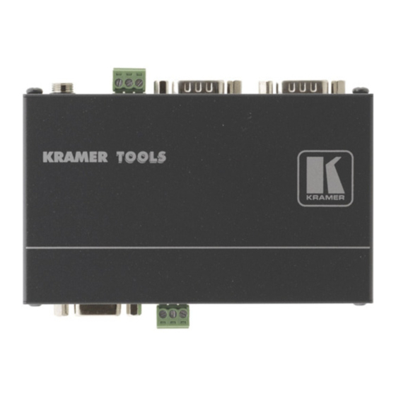
Table 1 define the front and rear panels of the VP-14xl. Figure 1: VP-14xl RS-232 Port Extender Front and Rear Panels Table 1: VP-14xl RS-232 Port Extender Front and Rear Panel Features Feature Function RS-232 IN 9-pin D-sub (F) Connector Connect to source computer 1 RS-485 IN 3-pin Removable Terminal Connect to source computer 2. -
Page 7: Connecting The Vp-14Xl Rs-232 Port Extender
3. If you are using the RS-485 input, set the RS-485 termination (see Section 6.1). 1 Switch OFF the power on each device before connecting it to your VP-14xl. After powering up your VP-14xl, switch on the power to each device... -
Page 8: Setting The Dip-Switches On The Vp-14Xl
7. Connect the 5V DC power adapter to the 5V DC socket and to the mains electricity. Note: Changing any DIP-switch requires that you either power cycle the VP-14xl or press the Reset button (see Table Setting the DIP-switches on the VP-14xl Moving a DIP-switch down turns the switch on, moving it up turns the switch off. -
Page 9: Setting The Addr Dip-Switches
Reply is taken from output 3 OFF OFF ON Note: When there is more than one VP-14xl attached to the RS-485 bus only one unit can have a reply source set, all other units must have DIP-switches 2, 3 and 4 set to OFF. -
Page 10: Hardware Mode
Hardware Mode In Hardware mode, the: • RS-232 data is passed from any input to all outputs • VP-14xl routes the reply from the output port defined by the DIP-switches 2, 3 and 4 (see Section 6.2). For reliable operation, only one port should be... -
Page 11: Serial Port Pinouts
Serial Port Pinouts Serial Port Pinouts Table 7 describes the pinouts of the 9-pin D-sub serial ports. Table 7: 9-Pin D-sub Serial Port Pinouts Function Receive Transmit Ground Note: Flow control signals are not supported. Table of Hex Codes for Serial Communication (Protocol 2000) The RS-232/RS-485 Protocol 2000 uses four bytes of information as shown in Table 8. -
Page 12: Table 9: Instruction Codes For The Vp-14Xl
For a single machine controlled via the serial port, always set M4…M0 = 1, and make sure that the machine itself is configured as MACHINE NUMBER = 1. Table 9: Instruction Codes for the VP-14xl INSTRUCTION DEFINITION FOR SPECIFIC INSTRUCTION... - Page 13 1. Any product which is not distributed by us or which is not purchased from an authorized Kramer dealer. If you are uncertain as to whether a dealer is authorized, please contact Kramer at one of the agents listed in the Web site www.kramerelectronics.com.
- Page 14 For the latest information on our products and a list of Kramer distributors visit www.kramerelectronics.com where updates to this user manual may be found. We welcome your questions, comments, and feedback. Safety Warning: Disconnect the unit from the power supply before opening/servicing.


Need help?
Do you have a question about the Tools VP-14xl and is the answer not in the manual?
Questions and answers