Advertisement
Table of Contents
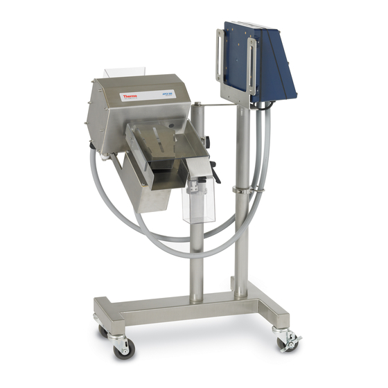
- 1 Metal Detector
- 2 Table of Contents
- 3 Deciding Which Model You Have
- 4 Getting Started-Compressed-Air Model
- 5 Installing Your APEX 500 Rx
- 6 Aligning the APEX 500 Rx in Your Production Line
- 7 Making the Power and Compressed-Air Connections
- 8 Making the Power Connections (Electric Reject)
- 9 Getting Started-Electric-Reject Model
- 10 Setting Passwords
- 11 Checking APEX Sensitivity
- 12 Fail-Safe Operation
- 13 Troubleshooting
- 14 Additional Information
- 15 Modifying 500 Rx Operating Parameters
- 16 Supplemental Information
- Download this manual
Advertisement
Table of Contents

Subscribe to Our Youtube Channel
Related Manuals for Thermo Scientific APEX 500 Rx


Summary of Contents for Thermo Scientific APEX 500 Rx
-
Page 1: Metal Detector
Thermo Scientific APEX 500 Rx Metal Detector User’s Guide REC 4345 Rev C Part number 109541—English... - Page 2 © 2011 Thermo Fisher Scientific, Inc. All rights reserved For future reference, write your APEX 500 Rx serial number below. APEX 500 Rx serial # = __________________________________ Page 2 Thermo Scientific—APEX 500 Rx User’s Guide...
-
Page 3: Table Of Contents
Deciding Which Model You Have ........... 5 Getting Started—Compressed-Air Model ........6 Installing Your APEX 500 Rx ............. 7 Aligning the APEX 500 Rx in Your Production Line ......11 Making the Power and Compressed-Air Connections ......14 ... - Page 4 (Page left blank intentionally) Page 4 Thermo Scientific—APEX 500 Rx User’s Guide...
-
Page 5: Deciding Which Model You Have
Deciding Which Model You Have Congratulations on the purchase of your new Thermo Scientific APEX 500 Rx metal detector! Please note there are two models of APEX Rx, as follows. Model 1 — The reject gate is powered by compressed air (the “compressed-air model”). -
Page 6: Getting Started-Compressed-Air Model
Getting Started—Compressed-Air Model The purpose of this manual is to help you get your compressed-air APEX 500 Rx up and running as quickly as possible. The following pages in the manual cover these topics. Installing your APEX 500 Rx ... -
Page 7: Installing Your Apex 500 Rx
Here are the instructions for attaching the input and output chutes to your APEX. 1) Match up the top and bottom halves of the input chute. 2) Slide the input chute into the search-head opening in the APEX. Thermo Scientific—APEX 500 Rx User’s Guide Page 7... - Page 8 Make sure the pins are resting in position A. 4) Insert the reject chute onto the reject solenoid shaft. Make sure the key is correctly aligned. Page 8 Thermo Scientific—APEX 500 Rx User’s Guide...
- Page 9 Tighten the M5 hex screw to 6 ft-lb (8N-m). 6) Attach the reject bin by doing the following. a) Slide the reject bin over the plastic pin on the APEX output chute. Thermo Scientific—APEX 500 Rx User’s Guide Page 9...
- Page 10 7) Loosen the wheel locks on the APEX carrier and roll the APEX into position in your production line. Lock the wheels again to ensure the carrier is totally immobilized on your factory floor. Page 10 Thermo Scientific—APEX 500 Rx User’s Guide...
-
Page 11: Aligning The Apex 500 Rx In Your Production Line
Aligning the APEX 500 Rx in Your Production Line The next step is to install the APEX (compressed-air and electric-reject models) in your production line. Please note the following important information about the APEX’s default settings. Important! The default settings for operating the APEX (which were set at the factory before your APEX was shipped) assume the APEX will be installed in your production line as follows. - Page 12 APEX, and use them to properly align the APEX in your production line. 1) Use this handle to set the angular alignment of the APEX. Page 12 Thermo Scientific—APEX 500 Rx User’s Guide...
- Page 13 2) Use this handle to set the vertical alignment of the APEX. 3) If desired, readjust the safety collar that prevents the APEX 500 Rx from falling to the floor. Loosen the bolts in the safety collar using a ¼" Allen (hexagonal) wrench, slide the collar to its new position, and tighten firmly to secure the safety collar.
-
Page 14: Making The Power And Compressed-Air Connections
1) Unscrew the 8 mounting bolts on the face of the APEX’s control panel, and remove the face plate. 2) Feed the main power cord through the hole in the frame and through the black plastic grommet in the base of the control panel, as shown below. Page 14 Thermo Scientific—APEX 500 Rx User’s Guide... - Page 15 Minimum air pressure = 60 psi (pounds per square inch) or 4.13 BAR Minimum air volume = 0.5 CFM (cubic feet per minute) or 0.014 CMM (cubic meters per minute) 1) Connect your compressed-air supply to the inlet on the APEX carrier. Thermo Scientific—APEX 500 Rx User’s Guide Page 15...
- Page 16 70 psi (4.82 BAR). 3) Congratulations! You have now finished installing your compressed-air model APEX Rx. Now go to page 20 of the manual, which tells you how to set passwords for APEX users. Page 16 Thermo Scientific—APEX 500 Rx User’s Guide...
-
Page 17: Making The Power Connections (Electric Reject)
1) Unscrew the 8 mounting bolts on the face of the APEX’s control panel, and remove the face plate. 2) Feed the main power cord through the hole in the frame and through the black plastic grommet in the base of the control panel, as shown below. Thermo Scientific—APEX 500 Rx User’s Guide Page 17... - Page 18 (E) wires to the correct terminals. The ground wire is connected to the grounding plate as shown below. 4) Push connector A firmly into connector B. 5) Place the face plate on the control panel and reattach using the eight mounting bolts. Page 18 Thermo Scientific—APEX 500 Rx User’s Guide...
-
Page 19: Getting Started-Electric-Reject Model
Getting Started—Electric-Reject Model The purpose of this manual is to help you get your electric-reject APEX 500 Rx up and running as quickly as possible. The manual covers the following topics. Installing your APEX 500 Rx Setting operator and other passwords ... -
Page 20: Setting Passwords
SF factory menu Factory – Model/machine Password required for SF factory menu every change More Information For more information about setting passwords, please see pages 249–253 in the main APEX User’s Guide. Page 20 Thermo Scientific—APEX 500 Rx User’s Guide... -
Page 21: Checking Apex Sensitivity
Checking APEX Sensitivity This section assumes you have installed the APEX 500 Rx in your production line, as described above. The next step is to test the sensitivity of the APEX—that is, test its ability to detect metallic contaminants—using the test spheres that are supplied with your APEX. -
Page 22: Fail-Safe Operation
Fail-Safe Operation The APEX 500 Rx has been designed for fail-safe operation. The following table outlines the fail-safe failures and the fail-safe actions taken by the APEX. Fail-safe failure Fail-safe system action No electrical input power or The reject gate closes. All product... -
Page 23: Troubleshooting
Verify aperture balance and input tuning settings are calibrated. Additional Information For additional information about resolving APEX problems, please see page 262 in the main APEX User’s Guide. Thermo Scientific—APEX 500 Rx User’s Guide Page 23... -
Page 24: Additional Information
For more information about changing the operating parameters (such as the reject-delay time, reject-duration time, and so on) for your APEX 500 Rx, please see the “Setting Up Pharmaceutical (500 Rx) Applications” section on pages 95–109 in the main APEX User’s Guide.
Need help?
Do you have a question about the APEX 500 Rx and is the answer not in the manual?
Questions and answers