
Related Manuals for Thermo Scientific Oretronic III


Summary of Contents for Thermo Scientific Oretronic III
- Page 1 Oretronic III Tramp Metal Dector Operating & Service Manual REC 4105, Rev. L Part Number 060298-English...
- Page 2 Number Date Specifics Revision A July 2000 Manual released. This revision documents version 1..01 of the Oretronic III Tramp Metal Detector Software Revision B October 2000 Manual revised to add information about the underbelt single coil model and remote front panel.
- Page 3 ©2009 Thermo Fisher Scientific. All rights reserved. This document is confidential and is the property of Thermo Fisher Scientific (Thermo Scientific). It may not be copied or reproduced in any way without the express written consent of Thermo Scientific. This document also is an unpublished work of Thermo Scientific.
- Page 5 About this Manual This manual provides the information you need to install, operate, and maintain the Oretronic III Tramp Metal Detector (TMD). This revision documents version 1.06 of TMD software. Read this manual before working with the system. For personal and...
- Page 6 Do not install, operate, or perform any maintenance procedures until you General have read the safety precautions presented below. Precaution WARNING Failure to follow safe installation servicing procedures could result in death or serious injury. Make sure only qualified personnel perform installation and maintenance procedures in accordance with the instructions in this manual.
- Page 7 CAUTION Keep hands and clothing away from all moving or rotating parts. CAUTION Do not place or store objects of any kind on the machine. CAUTION This machine should not be operated at more than the production rate stated on your Equipment Specification sheet or used in applications other than those stated in the original order.
-
Page 9: Table Of Contents
Contents Chapter 1 Introduction ............1-1 Overview ................1-1 Theory of Operation .............. 1-1 System Components ............1-4 Support Structure & Coils ..........1-6 Control Unit ................ 1-7 Features and Options ............1-7 Simplified Operator Interface ..........1-7 Remote Front Panel ............1-8 Synchronization of Transmitter Pulses....... - Page 10 Calibrating the Speed Sensor ..........2-16 Determining Values to Use for Initial Setup ......2-16 Determining Belt Speed ........... 2-17 Determining Clip Delay ............ 2-17 Determining Timed Delay ..........2-17 Chapter 3 Operating the TMD ..........3-1 Overview ................3-1 Operator Interface ..............
- Page 11 Front Panel Tests ............3-14 Software Version ............3-14 Exit ................3-14 Error Messages ............. 3-14 Error Conditions ............3-14 Fault Conditions ............3-15 Setting up the TMD ............. 3-16 Before You Begin ............. 3-16 Using the Display Scroll ........... 3-17 Entering Values ...............
- Page 12 Exception Responses .............. A-3 Master/Slave Timing Considerations ........A-3 TMD Holding Registers ............A-3 Appendix B - Remote Front Panel ........B-1 Overview ..................B-1 Routine Maintenance ..............B-1 Technical Specifications ..............B-2 Installing the Remote Front Panel ..........B-3 ...
- Page 13 Figure 1–6. TMD System Components: Dual Coil ........ 1-5 Figure 1–7. TMD System Components: Under Belt Single Coil ... 1-6 Figure 1–8. Oretronic III Control Unit ........... 1-7 Figure 2–1. Control Unit Mounting Dimensions ........2-7 Figure 2–2. Control Unit Enclosure - Bottom View ....... 2-8 Figure 2–3.
-
Page 15: Chapter 1 Introduction
The bulk material (or burden) can be product such as iron pellets, minerals, aggregates, coal, or coke. The Oretronic III TMD can be installed on conveyors with speeds up to 1,200 ft/min (6.1 m/s). In addition, because it is insensitive to materials... -
Page 16: Figure 1-1. Magnetic Fields Generated By The Tmd
Introduction PRIMARY MAGNETIC FIELD SECONDARY MAGNETIC FIELD TRAMP METAL TRANSMITTER COIL RECEIVER COIL Figure 1–1. Magnetic Fields Generated by the TMD The material on the conveyor belt also produces a secondary magnetic field. The two magnetic fields can be distinguished from each other by observing their decay times. -
Page 17: Figure 1-3. Ore/Tramp Metal Decay Time Comparison
(see Figure 1-3). Figure 1–3. Ore/Tramp Metal Decay Time Comparison The Oretronic III TMD is designed to take advantage of the difference in decay time by activating its measurement window (the point at which it reads the output signal) only after the magnetic field from the material on the conveyor has decayed and before the tramp's decay has ended (see Figure 1-4. -
Page 18: System Components
Introduction The Oretronic III TMD allows you to adjust both the sensitivity of the device to output signals and the location of the measurement window in the decay time. Signal strength is adjusted by a sensitivity factor; the measurement-timing window is adjusted based on a material type code factor. -
Page 19: Figure 1-6. Tmd System Components: Dual Coil
Introduction (Optional) (Optional) Figure 1–6. TMD System Components: Dual Coil Thermo Fisher Scientific Introduction REC-4105 Rev L... -
Page 20: Support Structure & Coils
Introduction (Optional) Figure 1–7. TMD System Components: Under Belt Single Coil Support Structure & The coils (or coil) are mounted on a rugged support structure made of non-conducting fiberglass material. On a dual coil TMD, the transmitter Coils coil is swing-mounted above the belt to protect the coil and support from being damaged by oversized material. -
Page 21: Control Unit
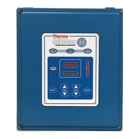
Figure 1-8 shows the Oretronic III control unit enclosure. Figure 1–8. Oretronic III Control Unit Features and The Oretronic III TMD includes a number of standard features and available options that enhance its performance in a conveyor system. Options Simplified Operator The operator interface to the TMD is a front panel on the control unit. -
Page 22: Remote Front Panel
Introduction The touch panel makes it easy to enter and change values and to scroll the displays. The displays indicate tramp count and coast count during normal operations and are used during setup and calibration. LEDs visible from outside the enclosure indicate NORMAL, BYPASS, and ALARM conditions and a bar graph displays signal strength. -
Page 23: High Pile Detector
Installation Placement, Standard System (D07328C-A002) System requirements for incorporating an under belt single coil Oretronic III TMD into a conveyor system can be found on the following Engineering Drawings in Appendix D of this manual: • Under Belt Single Coil Final Assembly (D07328C-A101) •... -
Page 24: Technical Specifications
Introduction This section lists the technical specifications for the Oretronic III Tramp Technical Metal Detector. Specifications apply to both dual coil and under belt Specifications single coil models unless otherwise noted. Belt Speed 5–1,200 ft/min (1–366 m/min) Construction (Coils and Support Assembly) - Page 25 Introduction Weight: 22 lb (10 kg) Maximum Distance from Coils: 10 ft (3 m) 50 ft (15 m) with optional junction box Environnemental Conditions Location: Indoor/outdoor Storage Temperature: –67º to 158º F (–55º to 70º C) ambient Operating Temperature: –40º to 122º F (–40º to 50º C) Humidity: 10 to 95% relative humidity, non-condensing Altitude:...
- Page 26 Introduction Overvoltage Category: Transient overvoltage according to installation category (Overvoltage Category II) Power Switch: On circuit board Displays/Keypad Display: Three seven-segment LEDs for counts One eight-character alphanumeric LED display Remote Display: Option allows a second display and keypad to be remotely mounted Bar Graph: 20 LED bars Status LEDs:...
- Page 27 Introduction Speed: Isolated Frequency range: 0.25–2,000 Hz (0.2 ms min. pulse width) 0.25–30 Hz (15 ms min. pulse width) Thresholds: 1.0 V min./3.0 V max. Hysteresis: 0.6 V min. Input impedance: 10 K Ω typical, 500 Ω max. Input current: –1 mA nominal Max.
- Page 28 Introduction Normal Indicator: Dry contact; 5 A, 250 VAC Note: The ALARM and NORMAL indicators are always in opposite states; they are opposite contacts of the same Form C relay Bypass Indicator: Dry contact; 5 A, 250 VAC Power On Indicator: Dry contact;...
-
Page 29: Chapter 2 Installing The Tmd
Chapter 2 Installing the TMD This chapter provides information about installing and setting up the Oretronic III TMD. It discusses installation considerations, provides procedures for mounting, and wiring, describes the hardware configura- tion, and provides procedures for determining initial setup parameters for the device. -
Page 30: Mounting Location
Installing the TMD The coil support structure and coil(s) must be mounted properly for the Mounting TMD to function correctly. Large metallic objects near the coil(s) will Location cause a reduction in signal strength. To prevent loss in signal strength, make sure that no metallic objects such as steel girders, deck plates, skirt boards, return idlers, or metal building walls are within 4 ft (1.2 m) of the receiver coil. -
Page 31: Safety Precautions
Installing the TMD Safety WARNING Precautions High voltage that may be present on leads could cause electrical shock. Disconnect incoming power at mains before beginning any installation or wiring procedures. Use extreme caution when testing in, on, or around the electronics, PC boards, or modules. There are voltages in excess of 115 V or 230 V in these areas. -
Page 32: Equipment Handling
Installing the TMD The TMD coil support structure and coil(s) are normally packaged on a Equipment wooden skid and may be lifted with a forklift or crane. Do not lift the Handling equipment using the support structure; use the exterior wooden structure. Use care when lifting this equipment to avoid damage to the coil(s). -
Page 33: Installing The Coil Support Structure And Coil For An Under Belt Single Coil Tmd
Installing the TMD 1. Assemble the coil support structure and the coils so that all electrical cables for the transmitter and receiver coils are on the same side of the conveyor. 2. Mount the transmitter coil to allow it to swing in the direction of belt travel at a height above the belt so it will clear normal conveyor loads. -
Page 34: Installing System Devices
Installing the TMD Idler spacing at the coil location must be greater than 4 ft (1.2 m). If for mechanical reasons this spacing is not possible, the distance may be reduced by using rubber impact-type idlers. Remove any deck plates, cross bracing, and return idlers located within 4 ft (1.2m) of the coil. -
Page 35: Mounting The Control Unit
Installing the TMD The control unit should be mounted in a vibration-free area less than 10 Mounting the Control ft (3 m) from the coils. Mount the control unit enclosure to a rigid, flat, Unit vertical surface using the 2-position mounting feet on the back of the enclosure (see figure 2-1) Figure 2-1. -
Page 36: Figure 2-2. Control Unit Enclosure - Bottom View
Installing the TMD WARNING Make sure the mounting surface is flat so that the fibreglass enclosure does not twist or warp when the mounting bolts are tightened. Follow this procedure to mount the control unit enclosure. 1. Open the enclosure door. 2. -
Page 37: Field Wiring The Tmd
Installing the TMD All wiring, except as noted, is the responsibility of the customer. Follow Field Wiring the the field wiring diagram for your system or refer to the Field Wiring Diagram (D07344A-E001) in Appendix D to connect system wiring to the CPU board in the control unit. -
Page 38: Figure 2-3. Terminal Block Locations On The Cpu Board
Installing the TMD Follow all cable number specifications on the Field Wiring Diagram Field Wiring (D07344A-E001) when connecting wiring to the CPU board. Figure 2-3 Procedure shows the locations of the terminal blocks. Figure 2–3. Terminal Block Locations on the CPU Board 2-10 Installing the TMD Thermo Fisher Scientific... -
Page 39: Connecting Incoming Power
Installing the TMD Use this procedure to wire the control unit. 1. Route incoming connections at line voltages above 30 V through a conduit hole in the bottom right of the enclosure so that they are protected by the power cover (see Figure 2-2). Leave enough loose wiring (about 8 in.) to allow the board to be moved without having to disconnect wires. -
Page 40: Configuring The Tmd
Installing the TMD 3. Route incoming power wiring through a conduit hole on the bottom right of the enclosure Use 14 AWG stranded copper wire. Maintain a gap of at least ½ in. from low voltage wires. Leave enough loose wiring to allow the board to be moved without having to disconnect wires. -
Page 41: Cpu Board Switch Settings
Installing the TMD FUNCTION Password protection Enable password protection software. Eliminate password. Speed sensor input Enable speed sensor input option. Speed sensor disabled. SYNC input Enable SYNC input on the slaves for SYNC input disabled. synchronization of transmitter pulses. (Required setting on the (Required when two detectors are within 30 master.) ft of each other.) -
Page 42: Figure 2-4. Switch Locations On The Cpu Board
Installing the TMD Figure 2–4. Switch Locations on the CPU Board 2-14 Installing the TMD Thermo Fisher Scientific REC-4105 Rev L... -
Page 43: Initial Power On
Installing the TMD Note: Both switches, SW2 (relay outputs) and SW3 (electronics), must be in the BYPASS position to disable alarms while setting up and calibrating the TMD. When the TMD is set up and operating properly, be sure to place BOTH of these switches in the NORMAL position before running production. -
Page 44: Calibrating The Speed Sensor
Calibrating The procedure is written as though you are familiar with the operator the Speed interface to the Oretronic III TMD. If you are not familiar with the operator interface, please read the detailed descriptions of the front panel Sensor keys, indicators, and displays in Chapter 3 of this manual before beginning this procedure. -
Page 45: Determining Belt Speed
Installing the TMD 1. Empty the conveyor belt of all material. 2. Stop the conveyor belt. 3. Place a mark on the belt that will be visible while the belt is running. 4. Start the conveyor belt. If your system does not use a speed sensor, you will need to know the Determining Belt belt speed in feet/minute. - Page 46 Installing the TMD To determine timed delay, clock the time, in seconds, that it takes for the mark on the belt to move from the receiver coil to the marking device. This value will be equal to: Distance (ft) x (Belt Speed (ft/min) x 60) 2-18 Installing the TMD Thermo Fisher Scientific...
-
Page 47: Chapter 3 Operating The Tmd
Oretronic III TMD. The operator interface, including all keys, indicators, and displays, is described. Procedures for initial setup and calibration are provided. You operate the Oretronic III TMD through the control unit. The Overview control unit is mounted locally, but it may be operated either locally or remotely. -
Page 48: Operating Modes
Operating the TMD Figure 3–1. Tramp Metal Detector Front Panel The TMD has two modes of operation: Run mode and Setup/Calibrate Operating Modes mode. When the TMD is in Run mode, the NORMAL LED is lit, the display shows the word COUNT, and the counter shows the total count of detected tramp. -
Page 49: Figure 3-2. Tmd Menu Tree
Operating the TMD Within the setup and calibrate high-level menus are the individual parameters and settings that define how your TMD is to operate. Figure shows the TMD menu tree. COUNT TMD is in normal Run mode PSWD N/Y If Y, password is required Calib? N/Y If Y, settings can be changed COIL BAL... -
Page 50: Front Panel Keypad
Operating the TMD The keys on the TMD front panel are soft touch keys on a flat panel. Front Panel Keypad The keys are used to set up and calibrate the TMD. Figure shows these keys on the front panel. The up and down SCROLL arrow keys move the scroll of display SCROLL Keys “screens”... -
Page 51: Reset Key
Operating the TMD The ENTER key is also used to clear error and fault messages (refer to Section “Error Messages”). The RESET key is used to reset the ALARM output after metal RESET Key detection. It also resets the coast count to zero. Pressing this key returns the TMD to normal Run mode after an alarm. -
Page 52: Front Panel Displays
Operating the TMD Note: At high belt speeds, the bar graph may not respond quickly enough to accurately indicate the signal strength of a metal trip. The front panel has two types of display indicators: an eight-character Front Panel alphanumeric display and a three-digit counter LED. Figure shows these Displays indicators. -
Page 53: Password Protection Screen
Operating the TMD Pressing the RESET key resets the coast counter to zero, returns the display to the total count display, and returns the TMD to Run mode (NORMAL LED is lit). Password protection is used to restrict access to the setup and calibration Password Protection settings. -
Page 54: Calibration Screens
Operating the TMD screens. If you just want to view the current settings, SCROLL down when PSWD= is displayed. To disable password protection, use the value keys to change PSWD Y to PSWD N. Note: To remove a forgotten password, set the SW1 DIP Switch to OFF and cycle the power. -
Page 55: Calibrate For Metal
Operating the TMD The next two screens are used to calibrate the sensitivity of the TMD for Calibrate for Metal detecting tramp metal. The first screen adjusts the coarse sensitivity of the tramp signal. The second screen adjusts the fine sensitivity. When you SCROLL to the first metal calibration screen, the display shows COARSE. -
Page 56: Est Cal
Operating the TMD You can start auto-calibration by pressing the ENTER key without changing the value. The counter then shows A2 and the display flashes AUTO CLP. When the calibration is complete, press ENTER again. The display flashes QUIK BAL while the system rebalances, and then returns to the CLP CORS display. -
Page 57: Exit
Operating the TMD This screen allows you to exit the calibration screens and return to Run Exit mode without having to SCROLL back up to the Run screen. The display shows EXIT?. To exit, press ENTER. These display screens are used to set up TMD operating parameters and Setup Screens options. -
Page 58: Bar/Rod Length
Operating the TMD refer to “Adjusting for Bar/Rod Detection” and “Passing Bars or Rods Undetected”. This screen is used to set the maximum length of the bar or rod for the Bar/Rod Length TMD to detect. The display shows BAR LEN. The counter shows the length in feet from 1.0 to 50.0. -
Page 59: Filter
Operating the TMD the number, the more gradual the slope. The smaller the number, the steeper the slope. This screen is for display purposes only. This screen is used to select the noise filter used on the TMD. There are Filter three filters to choose from. - Page 60 Operating the TMD These screens allow you to test the indicators and keys on the front Front Panel Tests panel. The first test screen is LAMP? N. Changing this to LAMP? Y and pressing ENTER tests the indicators by lighting each LED on the front panel individually.
- Page 61 Operating the TMD MESSAGE MEANING The detector cold started on power up. COLD ST Default values were used for calibration settings. Possible causes: Cold start DIP Switch is set to ON • Memory checksum problem • RESETDIS The reset disable input is open. (This input is used for the optional marker feature.) You cannot reset the detector until the input is closed by resetting the marker.
-
Page 62: Table 3-2. Fault Messages
Table 3–2. Fault Messages Setting up the This section guides you through the initial setup and calibration of your Oretronic III TMD. Once the TMD is set up correctly, few or no changes to the settings are required. Before You Begin... - Page 63 Operating the TMD When the TMD is in Setup/Calibrate mode, the display shows each Using the Display individual variable that needs to be set up. The counter shows the Scroll current (default) value of the variable. The up and down SCROLL arrow keys move the scroll of display “screens”...
- Page 64 Operating the TMD Set Up Displays Stop the conveyor belt. SETUP? Y Bump the conveyor belt until a 10-ft (3-m) section of belt, without splices or clips, is centered in the detection area. CLIP DLY There should not be a splice or clip within 4 ft (1.2 m) of the BAR SENS receiver coil on the return side.
- Page 65 Operating the TMD Calibration Scroll to the BELT SPD display. If your system uses a speed sensor, the belt speed determined by the sensor will be displayed in the counter. CALIB? Y If your system does not use a speed sensor, enter the belt speed in COIL BAL feet/minute.
- Page 66 Operating the TMD 13. Slide the piece of tramp metal completely through the detection Calibration area at least three more times, then press ENTER. The display shows MET DONE. The counter shows the new fine CALIB? Y sensitivity setting. Range: 0–999 COIL BAL 14.
- Page 67 Operating the TMD 20. Scroll down to the EXIT? display and press ENTER. Scroll to the high-level setup menu and put the TMD in back into Setup mode (SETUP? Y). If your system uses bar/rod detection, go on to Step 21. If you do not use bar/rod detection, make sure the counter value for the BAR SENS display is 0 (this turns off bar/rod detection) and go to Step 22.
- Page 69 You can expect the Oretronic III TMD system to operate satisfactorily Overview and hold its calibration for months with simple routine maintenance. The Oretronic III control unit is a solid-state device, and as such, requires minimal maintenance. Keep the area around the TMD free from rocks and material build-up.
- Page 70 Maintaining & Troubleshooting Troubleshooting If your TMD is not detecting reliably or your calibrations are providing unexpected results, there are several things you can do to determine the cause of the problem. Always begin with a visual inspection, not only of TMD components but also of the conveyor belt, the idlers, and all optional equipment.
- Page 71 Maintaining & Troubleshooting When you calibrate the TMD during initial setup, the microprocessor Diagnosing and “imprints” the signal level produced by the piece of tramp metal you use Correcting for the calibration. The TMD then trips when tramp producing that signal level or greater passes through the detector.
- Page 72 Maintaining & Troubleshooting WARNING Failure to follow safe installation servicing procedures could result in death or serious injury. Make sure only qualified personnel perform installation and maintenance procedures in accordance with the instructions in this manual. Allow only qualified electricians to open and work in the electronics cabinets, power supply cabinets, control cabinets, or switch boxes.
- Page 73 Maintaining & Troubleshooting WARNING K e ep h and s an d c lo t h i ng aw a y f r o m a ll m o vin g o r r ot at in g pa rts . 1.
- Page 74 Maintaining & Troubleshooting head pulley or tail pulley to see if the balance improves significantly, then adjust it to the best position possible. If moving the frame does not help balance then, go on to 4.4.2 Finding the Source of Mechanical or Electrical Noise. For a single coil TMD: •...
- Page 75 Maintaining & Troubleshooting False tripping often occurs from mechanical vibrations that produce Finding the background noise. The TMD software has signal processing to Source of recognize the difference between a signal from metal passing through Mechanical or the coils and a signal from metal vibrating in the region of the coils. Electrical Noise However, severe metal vibrations can sometimes produce the same signal as the metal passing through the coils.
- Page 76 Maintaining & Troubleshooting CAUTION K e ep h and s an d c lo t h i ng aw a y f r o m a ll m o vin g o r r ot at in g pa rts . 1.
- Page 77 Maintaining & Troubleshooting WARNING High voltage that may be present on leads could cause electrical shock. All switches must be OFF when checking input AC electrical connections, removing or inserting printed circuit boards, or attaching voltmeters to the system. Use extreme caution when testing in, on, or around the electronics cabinet, PC boards, or modules.
- Page 78 Maintaining & Troubleshooting 7. Scroll to the OP FREQ display and change the operating frequency value from 0 to one of the other values (0 = 900 Hz, 1 = 780 Hz, 2 = 660 Hz, 3 = 1020 Hz). 8.
- Page 79 Maintaining & Troubleshooting Note: Before beginning this procedure, make sure the FILTER setting is 1. Filter 1 provides the best reduction of product noise. Follow this procedure to adjust the sensitivity of the TMD for mineral ores. 1. Balance the coils as evenly as possible using the procedure from “Correcting Coil Imbalance”.
- Page 80 Maintaining & Troubleshooting You may want to try the procedure from Section “Finding the Source of Mechanical or Electrical Noise” to see if that may be the problem. The TMD bar/rod detection option allows you to set a specific Adjusting for sensitivity calibration for bars or rods that are small in diameter and one Bar/Rod to ten feet in length.
- Page 81 Maintaining & Troubleshooting 5. Follow the procedure in Correcting Coil Imbalance on page 4-4 to balance the coils. Follow the procedure in Mechanical or Electrical Noise on page 4-7 to reduce system noise. Some false trips may occur from the clips used for belt repair or Adjusting for Clip splicing.
- Page 82 Maintaining & Troubleshooting Follow this procedure to determine why the clip detector is not working properly. Note: You will need a digital volt meter (DVM) to complete this procedure. 1. Check the system wiring based on the wiring diagram for your system or the Field Wiring Diagram (D0744A-E001) in Appendix D.
- Page 83 Maintaining & Troubleshooting Note: The clip detector is to be mounted 3 to 4 inches away from the first idler toward the tail pulley and the coil support structure. If it is not mounted according to the installation placement drawings, the clip detector may intermittently miss clips.
- Page 84 Maintaining & Troubleshooting Note: The number of LEDs displayed for the clip(s) may vary slightly as the clip passes through from one time to the next. This is caused by a slight non-linearity in the electromagnetic field near the receiver coils and will not cause any problem.
- Page 85 Maintaining & Troubleshooting If the CLP FINE value reaches 500 and false trips are still occurring, scroll to the CLP CORS display and repeat this procedure from Step There are a number of reasons why the TMD may pass tramp Passing undetected.
- Page 86 Maintaining & Troubleshooting If the TMD does not trip, observe the bar graph. If the LED level on the bar graph does not increase when the tramp is passed through the coils, there is a more serious problem than a low sensitivity setting. Go on to “Testing for Coil or Junction Box Damage”...
- Page 87 Maintaining & Troubleshooting 10. Place the TMD in Calibrate mode and scroll to the COARSE display. 11. Using the up VALUE key, increase the COARSE value by 1 and press ENTER. 12. Place the TMD in Run mode, pass the test tramp through the coils, and check for a trip.
- Page 88 Maintaining & Troubleshooting 4. When 5 LEDs are lit, record the COARSE and FINE values. 5. Scroll to the MAT CODE display and decrease the value shown in the counter by 1. Press ENTER. 6. Balance the coils again using the procedure in Correcting Coil Imbalance on page 4-4.
-
Page 89: Figure 4-1. Terminals On The Cpu Board
Maintaining & Troubleshooting WARNING Failure to follow safe installation servicing procedures could result in death or serious injury. Make sure only qualified personnel perform installation and maintenance procedures in accordance with the instructions in this manual. Allow only qualified electricians to open and work in the electronics cabinets, power supply cabinets, control cabinets, or switch boxes. - Page 90 Maintaining & Troubleshooting Follow this procedure to test the transmitter coil if your system does not Testing the Transmitter have a junction box. Coil 1. Turn off power to the control unit (SW6). 2. Disconnect the transmitter coil wires from field terminals 4 and 5. 3.
- Page 91 Maintaining & Troubleshooting 3. Measure the resistance of the coil. If the resistance is greater than 500 ohms, the receiver coil is bad. If the receiver coil resistance is approximately 450–500 ohms, the receiver coil, its wiring, and its portion of the CPU board is all right. If your system uses a junction box, follow this procedure to test the receiver coil.
- Page 92 Maintaining & Troubleshooting the electronics cabinets, power supply cabinets, control cabinets, or switch boxes. WARNING High voltage that may be present on leads could cause electrical shock. All switches must be OFF when checking input AC electrical connections, removing or inserting printed circuit boards, or attaching voltmeters to the system.
- Page 93 Maintaining & Troubleshooting If the displays do not light, the TMD has been damaged and must be replaced. If the fuse tested bad in the first procedure: Replace the fuse with the correct sized fuse. Turn the power switch back on. If the displays do not light, turn the power switch off.
- Page 94 Maintaining & Troubleshooting The basic procedure for testing components is: Turn the power switch (SW6) off. Wire in a component. Turn the power switch on. Check the front panel. If the displays are lit, that component did not blow the fuse. Repeat the procedure for the next component.
- Page 95 Maintaining & Troubleshooting If you changed the value, rebalance the coils using the procedure in Correcting Coil Imbalance on page 4-4. 6. Scroll to the COARSE display. 7. Set the coarse sensitivity value to 6 and press ENTER. If a BALANCE fault message appears in the display, rebalance the coils using the procedure in Correcting Coil Imbalance on page 4-4.
- Page 96 Maintaining & Troubleshooting If your TMD is passing bars or rods undetected, use the procedure in this section to help determine the cause. The procedure is written as though you are familiar with using the operator interface. If you are not familiar with the operator interface, please read the detailed descriptions of the front panel keys, indicators, and displays in Chapter 3 of this manual before beginning the procedures.
-
Page 97: Table 3-1. Error Messages
Maintaining & Troubleshooting 3. Turn on power to the control unit (SW6) and wait 4 seconds. Default values will be installed on power up. 4. Set DIP Switch position 8 on SW1 back to OFF. Note: It is very important that you set the DIP Switch to OFF so you do not accidentally install default values if the machine is power cycled. -
Page 98: Table 4-1. Error Messages
Maintaining & Troubleshooting error number. An E in the first digit of the counter indicates an error rather than a fault condition. To clear an error message from the Run screen, press the ENTER key. Correct the error condition, scroll to the error message display (the last display in the scroll), and press ENTER to clear the message. -
Page 99: Table 4-2. Fault Messages
Maintaining & Troubleshooting MESSAGE MEANING Indicates an open or short circuit has XMIT FLT been detected in the transmitter coil. May be due to faulty wiring or actual fault condition. Indicates a microprocessor problem. SELFTEST The coil imbalance exceeds the ability BALANCE of the detector to electronically “self- balance.”... - Page 101 Replacement Parts This chapter provides information about service, repair, and replacement parts for your ORETRONIC III TMD. It includes the telephone numbers for various departments at Thermo Scientific. The procedure for ordering replacement parts and a Return Material Authorization form are also included in this chapter.
- Page 102 2. Locate the part on the engineering drawings in Appendix D. 3. Find the corresponding part number in the parts list. 4. Before you contact Thermo Scientific for your parts, make sure you have the following information: • Machine model and serial number •...
- Page 103 Parts Lists parts for the Oretronic III TMD control unit. All other replaceable parts for the Oretronic III TMD are shown on the engineering drawings in Appendix D. The drawings help you accurately identify the part(s) you need, and the parts lists on the drawings provide part numbers and descriptions.
- Page 104 Service, Repair & Replacement Parts Phone/Fax Australia +61 (0) 8 8208-8200 Contact for +61 (0) 8 8234-3772 fax Thermo Fisher Canada Scientific +1 905-888-8808 +1 905-888-8828 fax Offices Chile +56 2 378 5080 +56 2 370 1082 fax China +86 8008105118 +86 (0) 2164451101 fax Germany +49 (0) 208-824930...
- Page 105 Appendix A - TMD Modbus Interface This Appendix provides information about the Modbus protocol implemented for communications between the ORETRONIC III Tramp Metal Detector (TMD) and an intelligent host or PLC. It deals only with the protocol as used for this particular interface.
- Page 106 (Illegal Data Address). This is a sub-set of normal Modbus slave responses. Broadcast messages are not supported in this implementation. Following are examples of Modbus query messages and their responses. Example: Read In this example, the host reads holding registers 40003–4005 from slave Holding Registers device 5.
-
Page 107: Table A-1. Tmd Exception Responses
When the TMD is unable to respond normally to a Modbus query, it will Exception return an appropriate exception response to the host. Responses Table A-1 shows the two-digit code and the meaning of each exception response. EXCEPTION CODE MEANING Illegal Function The function code received in the query is not supported. - Page 108 Table A-2 describes each holding register used for Modbus communication with the TMD. In the table, Type “I” is a signed integer; Type “P” means that data is packed within the bytes. MSB = most significant byte, LSB = least significant byte. Thermo Fisher Scientific REC-4105 Rev L...
- Page 109 R E G I S T E R AC C E S S T Y P E D E S C R I P T I O N AD D R E S S 40001 Read Only Coast count = Number of pieces of metal counted since the last time the detector was RESET.
- Page 110 R E G I S T E R AC C E S S T Y P E D E S C R I P T I O N AD D R E S S 0 x F F - N o k e y wa s p r e s s e d 0 x F E - S C R O L L u p k e y wa s p r e s s e d 0 x F D - R E S E T k e y wa s p r e s s e d 0 x F B - V AL U E u p k e y wa s p r e s s e d...
- Page 111 R E G I S T E R AC C E S S T Y P E D E S C R I P T I O N AD D R E S S 40046 Read Only Second general purpose status register, which is used for diagnostic purposes.
- Page 112 R E G I S T E R AC C E S S T Y P E D E S C R I P T I O N AD D R E S S 40032 Read Only Indicates how many LEDs are lit on the bar graph. Uni-polar mode: M S B = 0 x 0 0 L S B = N u m b e r o f L E D b a r s l i t...
- Page 113 R E G I S T E R AC C E S S T Y P E D E S C R I P T I O N AD D R E S S 40042–40044 Read Only Packed ASCII representation of the 3-digit counter LED. I n t e g e r 0 - L e f t m o s t d i g i t ( R e g .
- Page 115 Appendix B - Remote Front Panel This Appendix describes the optional remote front panel for the Oretronic III TMD. It includes technical specifications, wiring procedures, instructions for setup and operation, and a spare parts list. The operator interface to the TMD is a front panel on the control unit.
- Page 116 This section lists the technical specifications that pertain to the remote Technical front panel of an Oretronic III Tramp Metal Detector. Specifications Enclosure Type: NEMA 4X, non-metallic Size: 11.20 in.
- Page 117 Maximum Non-Destructive Input Voltage: 150/300 VAC for one minute Overvoltage Category: Transient overvoltage according to installation category (Overvoltage Category II) Power Switch: On chassis Displays/Keypad Display: Three seven-segment LEDs for counts One eight-character alphanumeric LED display Bar Graph: 20 LED bars Status LEDs: Red for ALARM, green for NORMAL, yellow for BYPASS Calibrate LED:...
- Page 118 WARNING High voltage that may be present on leads could cause electrical shock. All switches must be OFF when checking input AC electrical connections, removing or inserting printed circuit boards, or attaching voltmeters to the system. Use extreme caution when testing in, on, or around the electronics cabinet, PC boards, or modules.
-
Page 119: Figure B-1. Remote Front Panel Dimensions
Figure B–1. Remote Front Panel Dimensions WARNING Make sure the mounting surface is flat so that the fibreglass enclosure does not twist or warp when the mounting bolts are tightened. Thermo Fisher Scientific REC 4105 Rev L... - Page 120 Follow this procedure to mount the remote front panel enclosure. 1. Open the enclosure door. 2. Bolt the enclosure to a flat, vertical surface using the 2-position mounting feet on the back of the enclosure (see Figure B-1). 3. Punch the required conduit holes in the bottom of the enclosure for the power supply cable and the communications cable(s).
-
Page 121: Figure B-2. Interior Of The Remote Front Panel Enclosure
• Stranded, rather than solid, wire should be used. This wiring should be long enough, and routed, to allow the chassis to be removed from the front for servicing. • Connect the shield only where shown. • Never use a “megger” to check the wiring. •... - Page 122 2. Route incoming power connections through a conduit hole in the bottom right of the enclosure (see Figure B-1). Use 14 AWG stranded copper wire. Maintain a gap of at least ½ in. from low voltage wires. Leave enough loose wiring (about 8 in.) to allow the chassis cover to be moved without having to disconnect wires.
-
Page 123: Table B-1. Comm Switch Settings
4. Wire the HOT input power to the terminal labeled “H.” 5. Wire the NEUTRAL input power to the terminal labeled “N.” Note: Make sure the chassis cover is closed before applying power. 6. Put the POWER switch on the chassis cover in the “ON” position. Setting the There are four DIP Switches on the inside of the enclosure door that must be set correctly for the remote front panel. - Page 124 The list below provides part numbers and descriptions of the replaceable Parts List parts for the ORETRONIC III TMD remote front panel. Refer to the parts list in Chapter 5 and the engineering drawings in Appendix D for other TMD system part numbers. The drawings help you accurately identify the part(s) you need, and the parts lists on the drawings provide part numbers and descriptions.
- Page 125 Appendix C Appendix C - Electronically Simulated Tramp (EST) This appendix introduces you to Electronically Simulated Tramp (EST), a specially designed optional system for your TMD. EST works as a quality assurance check for your TMD to ensure the transmitter and receiver coils are operating properly.
- Page 126 Note: Do not tighten the bolts securely at this time. See Appendix D for the engineering drawing related to electrical Electrical installation. Installation 1. At the TMD control panel, from the RUN menu, scroll to the Calibration CALIBRATION menu press the value up arrow until the display and Setup toggles to Y 2.
- Page 127 2. Press ENTER 3. Scroll through the SETUP menu until EST INT displays 4. Press ENTER The current interval displays. 5. Use the arrow keys to set the designated interval time between 1 and 24 hours. Note: When you set the calibration reading and the interval you must scroll back through the menus until you reach the RUN menu.
- Page 128 EST Test performs an EST test on demand. A test on demand can be done in either calculation or normal mode of operation. An EST test done on demand in NORMAL operating mode is identical to an EST test done automatically using the EST Time Interval. If the test fails, the ALARM LED lights and the alarm output is activated.
- Page 129 Appendix D Engineering Drawings This Appendix contains the engineering drawings for your Oretronic III Tramp Metal Detector system. The following drawings are included: Field Wiring Diagram (D07344A-E001) Field Wiring Diagram (D07344A-E002) Field Wiring Diagram (D07344A-E031) Field Wiring Diagram (D07344B-E010) Field Wiring Diagram...
- Page 130 Outline, Mounting and Assembly, Coil Stand (D07328C-A003) Outline & Mounting Dimensions, Clip Detector (C07328C-B003) Outline & Mounting Dimensions, Flag Drop Marker (B07328C-B004) Outline & Mounting Dimensions, Spray Marker (D07344B-B007) Outline & Mounting Dimensions, Alarm Horn (B07328C-B005) Outline & Mounting dimensions, Rotating Beacon Assembly (B07328C-B006) Outline, Mounting and Installation, High Pile Detector (B07328C-B007)
Need help?
Do you have a question about the Oretronic III and is the answer not in the manual?
Questions and answers