
Related Manuals for Kramer VP-790


Summary of Contents for Kramer VP-790
- Page 1 K R A ME R E LE CT R O N IC S L TD . USER MANUAL MODEL: VP-790 Genlock Presentation Switcher/Scaler P/N: 2900-300093 Rev 4...
-
Page 4: Table Of Contents
Overview Using the IR Transmitter Defining the VP-790 Genlock Presentation Switcher/Scaler Installing in a Rack Connecting the VP-790 Configuring the VP-790 via the OSD MENU Screens The Input Screen The Picture Screen The Output Screen The PIP Screen The Multi-unit Screen... - Page 5 Figures Figure 1: VP-790 Genlock Presentation Switcher/Scaler Front Panel Figure 2: VP-790 Genlock Presentation Switcher/Scaler Rear Panel Figure 3: Connecting the VP-790 Genlock Presentation Switcher/Scaler Figure 4: MENU Items Figure 5: Input Screen Figure 6: Picture Screen Figure 7: Output Screen...
-
Page 6: Introduction
Introduction Welcome to Kramer Electronics! Since 1981, Kramer Electronics has been providing a world of unique, creative, and affordable solutions to the vast range of problems that confront the video, audio, presentation, and broadcasting professional on a daily basis. In recent years, we have redesigned and upgraded... -
Page 7: Getting Started
Avoid interference from neighboring electrical appliances that may adversely influence signal quality Position your Kramer VP-790 away from moisture, excessive sunlight and dust This equipment is to be used only inside a building. It may only be connected to other equipment that is installed inside a building. -
Page 8: Recycling Kramer Products
Kramer Electronics has made arrangements with the European Advanced Recycling Network (EARN) and will cover any costs of treatment, recycling and recovery of waste Kramer Electronics branded equipment on arrival at the EARN facility. For details of Kramer’s recycling arrangements in your particular country go to our recycling pages at http://www.kramerelectronics.com/support/recycling/. -
Page 9: Overview
Overview The VP-790 is a proscale genlock presentation scaler/switcher with edge blending, warping and genlocking. The unit includes a powerful software tool to generate custom warp maps to fit any projection surface. The unit takes one of the input signals (RGB component, computer graphics,... - Page 10 Front panel lockout, as well as input lock and save lock features via the OSD Control your VP-790 directly via the front panel push buttons, or: By RS-232 serial commands transmitted by a touch screen system, PC, or other serial controller ...
-
Page 11: Using The Ir Transmitter
The VP-790 is housed in a 19” 1U rack mountable enclosure, with rack “ears” included and is fed from a 100-240 VAC universal switching power supply. Using the IR Transmitter You can use the IR transmitter to control the machine via the built-in IR receiver on the front panel or, instead, via an optional external IR receiver (Model: C-A35M/IRR- 50). -
Page 12: Figure 1: Vp-790 Genlock Presentation Switcher/Scaler Front Panel
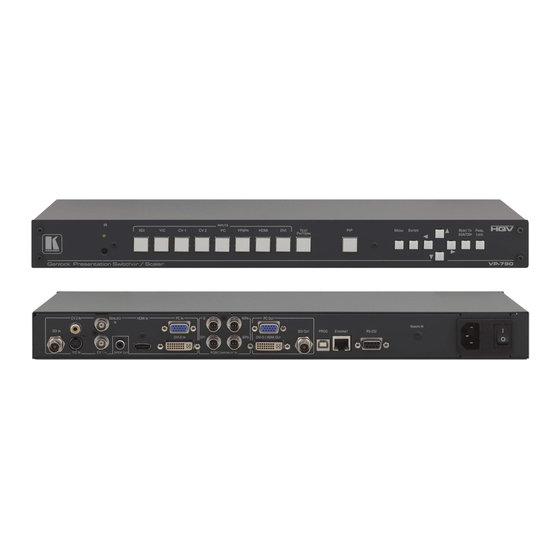
Figure 1: VP-790 Genlock Presentation Switcher/Scaler Front Panel Feature Function IR Receiver Receives signals from the remote control transmitter INPUT Press to select the SDI input Selector Press to select the s-Video input Buttons CV 1 Press to select the composite video 1 input... -
Page 13: Figure 2: Vp-790 Genlock Presentation Switcher/Scaler Rear Panel
Figure 2: VP-790 Genlock Presentation Switcher/Scaler Rear Panel Feature Function SDI IN BNC Connector Connect to the SDI source Y/C IN 4-pin Connector Connect to the s-Video source CV 2 IN RCA Connector Connect to the composite video 2 source... -
Page 14: Installing In A Rack
Installing in a Rack This section provides instructions for rack mounting the unit. VP-790 - Installing in a Rack... -
Page 15: Connecting The Vp-790
Connecting the VP-790 Always switch off the power to each device before connecting it to your VP-790. After connecting your VP-790, connect its power and then switch on the power to each device. You do not have to connect all the inputs and outputs, connect only those that are required. -
Page 16: Figure 3: Connecting The Vp-790 Genlock Presentation Switcher/Scaler
13. Connect the audio output signal to the S/PDIF OUT digital audio acceptor, as required (not shown in Figure 14. Connect the power cord (not shown in Figure Figure 3: Connecting the VP-790 Genlock Presentation Switcher/Scaler VP-790 - Connecting the VP-790... -
Page 17: Configuring The Vp-790 Via The Osd Menu Screens
Screens The VP-790 uses an on-screen display (OSD) menu for system configuration. The menu appears as an overlay over any images that are output from the VP-790. There are seven sub-menus (the PIP and Multiunit menus automatically replace each other in the Single Unit mode and the Multi-unit mode, respectively) that are used to configure the VP-790. -
Page 18: The Input Screen
Select the DVI input color format: RGB, YUV or Auto HDMI Color Select the HDMI input color format: RGB, YUV or Auto Format Component Color Select the Component Video input color format: RGB, YUV or Auto Format VP-790 - Configuring the VP-790 via the OSD MENU Screens... - Page 19 Adjust the frequency For UXGA inputs Phase Adjust the phase: 0 to 31 Auto image Assesses the image and improves the quality accordingly, by automatically adjusting the phase, frequency and position VP-790 - Configuring the VP-790 via the OSD MENU Screens...
-
Page 20: The Picture Screen
Select On to reduce luminance to chrominance crosstalk which appears as a coarse rainbow pattern or random colors in regions of fine details For composite video signals only (CVBS1 or CVBS2). VP-790 - Configuring the VP-790 via the OSD MENU Screens... -
Page 21: The Output Screen
Native: the output resolution is automatically set to the native screen resolution of the connected display DVI Forced: outputs with 24 bit color depth irrespective of the supported standard of the display VP-790 - Configuring the VP-790 via the OSD MENU Screens... - Page 22 DVI and HDMI. The filter strength slider is always available and the strength can be changed but it has no effect to a currently displayed interlace mode or video input port. VP-790 - Configuring the VP-790 via the OSD MENU Screens...
- Page 23 You can configure the aspect ratio of any output image to fit your application. The VP-790 offers six different aspect ratio settings: Best Fit, Letterbox, Follow Output, Virtual Wide, Follow Input, and Custom. Here is how each of these settings works.
-
Page 24: The Pip Screen
Is available only if Free H/V is selected for PIP Position V-Position Set the vertical position of the PIP on the displays available only if Free H/V is selected for PIP Position VP-790 - Configuring the VP-790 via the OSD MENU Screens... - Page 25 6.4.1 The PIP Feature The VP-790 PIP feature lets you show two images on one screen: the main window and the PIP window. If the main input channel is HDMI, DVI, DVI-A, VGA or COMPONENT, the PIP source can be selected from CVBS1, CVBS2, S-VIDEO or HD-SDI If the main input...
-
Page 26: The Multi-Unit Screen
Section 7.3.3) 6.4.1.2 Selecting the PIP Source To select a PiP source you have to set the VP-790 to any of the PiP display mode configurations. From the PIP menu, select the PIP source. The Multi-unit Screen Multiple screens can be set in a matrix to provide a larger display that provides a resolution that is higher than that of a single display. -
Page 27: Figure 9: Audio Screen
The area between the edge and the start of the blend area is black. The total number of pixels of the blend area and the offset region is limited by the same amount of pixels as for an offset of zero VP-790 - Configuring the VP-790 via the OSD MENU Screens... - Page 28 The corners of the non-blend region can be moved to allow tracking of the edge of the projection field of adjacent projectors VP-790 - Configuring the VP-790 via the OSD MENU Screens...
-
Page 29: The Geometry Screen
Set to a preset warp configuration: Off, 1 to 8 Warp maps created with the “Warp Generator” PC application can be uploaded into VP-790 and processed accordingly Reset All Resets to default view VP-790 - Configuring the VP-790 via the OSD MENU Screens... -
Page 30: The Setup Screen
Recalls a profile from 1 to 4 From Save Profile Save up to four profiles 1 to 4 Switching Set the switching transition mode: Freeze, Blank, Fast Fade or Slow Fade Transition VP-790 - Configuring the VP-790 via the OSD MENU Screens... - Page 31 When operating in the Multi-unit mode, the same frame lock should be defined in all the units in the matrix. Factory Reset Select Yes to reset your VP-790 to its preset default settings Operation Set the Operation Mode: PIP/Single or Multiunit...
-
Page 32: The Info Screen
From the Information screen (see Figure 12) you can verify the input resolution, the output resolution, the SYNC mode, as well as the firmware revision, DHCP status and IP address: Figure 12: Information Screen VP-790 - Configuring the VP-790 via the OSD MENU Screens... -
Page 33: Controlling The Vp-790
To connect to the VP-790 via RS-232, connect the RS-232 9-pin D-sub rear panel port on the VP-790 unit via a 9-wire straight cable (only pin 2 to pin 2, pin 3 to pin 3, and pin 5 to pin 5 need to be connected) to the RS-232 9-pin D-sub port on your... -
Page 34: Figure 13: Local Area Connection Properties Window
7.3.1 Connecting the ETHERNET Port Directly to a PC (Crossover Cable) You can connect the Ethernet port of the VP-790 to the Ethernet port on your PC, via a crossover cable with RJ-45 connectors. This type of connection is recommended for identification of the factory default IP Address of the VP-790 during the initial configuration. -
Page 35: Figure 14: Internet Protocol (Tcp/Ip) Properties Window
7.3.2 Connecting the ETHERNET Port via a Network Hub (Straight- Through Cable) You can connect the Ethernet port of the VP-790 to the Ethernet port on a network hub or network router, via a straight-through cable with RJ-45 connectors. 7.3.3... -
Page 36: Figure 16: Web Browser Address Bar
Access the Blendwidth, Blend Curve Type and Black-Level Uplift submenus Geometry Select the: Application, Location and Discrete Warp Map (see Section 6.6) Set the Horizontal Keystone, Vertical Keystone, Pincushion/Barrel distortion and Rotation Access the Diagonal Projection submenu Reset to default values VP-790 - Controlling the VP-790... -
Page 37: Controlling Via The Infrared Remote Control Transmitter
Select the component video input HDMI Select the HDMI input Select the DVI input TEST Select the test pattern PATTERN inputs. Cycles between different patterns with each Figure 17: Infrared Remote Control Transmitter press of the button VP-790 - Controlling the VP-790... -
Page 38: Firmware Upgrade
Firmware Upgrade You can upgrade the VP-790 via the Kramer VP-790 Updater Tool software. The latest version of firmware can be downloaded from the Kramer Web site at www.kramerelectronics.com. Installing the VP-790 Updater Tool Download the VP-790 Updater Tool software from http://www.kramerelectronics.com. -
Page 39: Figure 19: Choose Destination Location Window
2. Click Next. The Select Installation Folder window appears: Figure 19: Choose Destination Location Window 3. Click Browse to select the destination folder. 4. When finished, click Next. The Confirm Installation window appears: Figure 20: Confirm Installation VP-790 - Firmware Upgrade... -
Page 40: Figure 21: Installation Progress Window
Figure 21: Installation Progress Window Then the Installation Complete window appears: Figure 22: Installation Complete Window 6. Click Close. An icon appears on the desktop and a shortcut appears in the Start Menu Programs folder in the Kramer sub-folder. VP-790 - Firmware Upgrade... -
Page 41: Saving User Settings
If you want to backup the user settings before upgrading the machine, you can do it through the VP-790 Web pages. To do so, type the local IP address for the VP-790 in the Web browser’s address bar and press the ENTER button. - Page 42 BREC file to be programmed into the Unit. 6. Click Update Firmware. When the VP-790 has finished programming you will see a “Firmware update complete”, dialog box (this will take a minute or two). 7. After firmware update is complete, click OK.
-
Page 43: Technical Specifications
720p 1080i @60 1080p @30 1080p @60 480p 1080i @50 1080p @24 1080p @50 HDMI Input Resolutions (Computer): DOS, VGA to WUXGA up to 165 MHz pixel clock. 9.1.2 PC Input Resolutions From VGA to WUXGA. VP-790 - Technical Specifications... -
Page 44: Output Resolutions
720p60 1280x768@60 1600x1200@50 1080p23.976 1280x800@60 1600x1200@60 1080p24 9.2.1 SDI Output Resolutions SMPTE 292M, SMPTE 259M-C and SMPTE 424M compliant, accepts (484i) 480i, 576i, 720, 1080i and 1080p single link formats at 270Mb, 1.485Gb or 2.97Gb rates. VP-790 - Technical Specifications... -
Page 45: Rs-232 Communication Protocol
9.2.2 PC Output Resolutions From VGA to WUXGA, up to 165 MHz pixel clock. RS-232 Communication Protocol You can download the VP-790 RS-232 communication protocol online guide from the VP-790 Web page. VP-790 - Technical Specifications... - Page 47 For the latest information on our products and a list of Kramer distributors, visit our Web site where updates to this user manual may be found. We welcome your questions, comments, and feedback. Web site: www.kramerelectronics.com E-mail: info@kramerel.com SAFETY WARNING...
Need help?
Do you have a question about the VP-790 and is the answer not in the manual?
Questions and answers