Table of Contents
Advertisement
Quick Links
Download this manual
See also:
Quick Manual
Advertisement
Table of Contents

Related Manuals for Kramer VP-740


Summary of Contents for Kramer VP-740
-
Page 1: User Manual
Kramer Electronics, Ltd. USER MANUAL Model: Presentation Scaler / Switcher... -
Page 2: Table Of Contents
Contents Contents Introduction Getting Started Overview Your VP-740 Presentation Scaler / Switcher Installing the VP-740 Industrial Version on a Rack Connecting the VP-740 Presentation Scaler / Switcher Connecting a PC Understanding the PIP Feature Activating the PIP Feature PIP Characteristics... - Page 3 Contents Figures Figure 1: VP-740 Presentation Scaler / Switcher Industrial Version Figure 2: VP-740 Presentation Scaler / Switcher Home Version Figure 3: Connecting the VP-740 Rear Panel Figure 4: Connecting the PC Figure 5: OSD PIP Status Figure 6: Locking / Unlocking the Front Panel Figure 7: OSD Screen Icons Figure 8: First OSD Screen: the “Image Tuning”...
- Page 4 Table 8: Technical Specifications of the VP-740 (Input Signal – DVI) Table 9: Technical Specifications of the VP-740 (Input Signal – HDTV) Table 10: Technical Specifications of the VP-740 (Output Signal – RGB / DVI Mode) 38 Table 11: RS-232 Protocol...
-
Page 5: Introduction
2 We recommend that you use only the power cord that is supplied with this machine 3 Download up-to-date Kramer user manuals from the Internet at this URL: http://www.kramerelectronics.com 4 The complete list of Kramer cables is on our Web site at http://www.kramerelectronics.com... -
Page 6: Overview
Overview Overview The VP-740 Presentation Scaler / Switcher is a high quality graphics and video scaler, scaling any input format and resolution to a user-defined output resolution. In particular, the VP-740 Presentation Scaler / Switcher: Switches between the sources using FTB™ (Fade-Thru-Black) -
Page 7: Your Vp-740 Presentation Scaler / Switcher
(often associated with low quality cables) Avoid interference from neighboring electrical appliances and position your Kramer VP-740 away from moisture, excessive sunlight and dust Your VP-740 Presentation Scaler / Switcher The VP-740 Presentation Scaler / Switcher comes in two versions—an industrial version (illustrated in Figure 1) and an elegant home version (illustrated in Figure 2)—both are defined in Table 1 and Table 2. -
Page 8: Figure 1: Vp-740 Presentation Scaler / Switcher Industrial Version
Your VP-740 Presentation Scaler / Switcher Comp 1 Comp 2 100-240 VAC INPUTS Comp 1 50/60 Hz CV 2 CV 1 12 VDC RS-232 Comp 2 OUTPUTS YC 2 YC 1 Figure 1: VP-740 Presentation Scaler / Switcher Industrial Version KRAMER: SIMPLE CREATIVE TECHNOLOGY... -
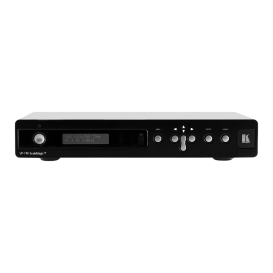
Page 9: Figure 2: Vp-740 Presentation Scaler / Switcher Home Version
Your VP-740 Presentation Scaler / Switcher Figure 2: VP-740 Presentation Scaler / Switcher Home Version Table 1: Front Panel VP-740 Presentation Scaler / Switcher Features Feature Function POWER Switch Illuminated switch supplying power to the unit STATUS Display Displays the status (see section 8) -
Page 10: Table 2: Rear Panel Vp-740 Presentation Scaler / Switcher Features
Your VP-740 Presentation Scaler / Switcher Table 2: Rear Panel VP-740 Presentation Scaler / Switcher Features Feature Function R/Pr BNC Connector G/Y BNC Connector Connect to the RGBHV acceptor (or the component video acceptor B/Pb BNC Connector BNC Connector BNC Connector... -
Page 11: Installing The Vp-740 Industrial Version On A Rack
Installing the VP-740 Industrial Version on a Rack Installing the VP-740 Industrial Version on a Rack This section describes what to do before installing on a rack and how to rack mount. Before Installing on a Rack How to Rack Mount... -
Page 12: Connecting The Vp-740 Presentation Scaler / Switcher
10. Connect a PC (optional), as section 6.1 describes. 1 Switch OFF the power on each device before connecting it to your VP-740. After connecting your VP-740, switch on its power and then switch on the power on each device 2 Y/R, Pb/Cb/G, Pr/Cr/B is also known as Y, B-Y, R-Y, or YUV or Y, Pb, Pr 3 The Comp 1 and the Comp 2 INPUTS RCA connectors are interchangeable. -
Page 13: Figure 3: Connecting The Vp-740 Rear Panel
Connecting the VP-740 Presentation Scaler / Switcher Projector Plasma Display Computer Graphics Source RS-232 DVI Graphics Source Camera (RGB) Source Figure 3: Connecting the VP-740 Rear Panel... -
Page 14: Connecting A Pc
Connecting the VP-740 Presentation Scaler / Switcher 6.1 Connecting a PC You can connect a PC (or other controller) to the VP-740 via the RS-232 port for remote control, and for upgrading the firmware. To connect a PC to a VP-740 unit, using the Null-modem adapter provided... -
Page 15: Understanding The Pip Feature
Understanding the PIP Feature Understanding the PIP Feature The Picture-in-Picture inserter (PIP) is used for the simultaneous display of video and graphic sources, and lets you display: An inserted video source PIP over a graphic source An inserted graphic source PIP over a video source Your Presentation Scaler / Switcher automatically recognizes and displays only the relevant sources, as the following two examples illustrate:... -
Page 16: Pip Characteristics
Menu (see section 8.4.3), using the remote control transmitter or the front panel OSD buttons 1 Label and frame disappear according to the Time Out Setting in the utilities Menu (see section 8.4.5) 2 Adjustment range is between –32 and +32 (default is –31) KRAMER: SIMPLE CREATIVE TECHNOLOGY... -
Page 17: Locking And Unlocking The Front Panel
You can lock the front panel and control from the infra-red remote control transmitter to safeguard the settings on the VP-740. To lock the front panel completely (none of the buttons are active): Press and hold the MENU front panel OSD button or the MENU key on... -
Page 18: Operating The Vp-740 Via The Osd Menu Screen
Infra-red remote control transmitter MENU key and DIRECTION keys (see section 8.6) RS-232 remote control The VP-740 also includes a front panel SOURCE button that scans the inputs (AV-1, AV-2, YC-1, YC-2, Comp 1, Comp 2, VGA, and DVI) until it locates an active source. -
Page 19: The Image Tuning Menu Screen
Operating the VP-740 via the OSD MENU Screen Use the OSD Menu as follows: Press the MENU front panel OSD button or the MENU key on the remote control transmitter (see Figure 44) to display the first OSD screen Press the MENU front panel OSD button or the MENU key on the infra-red remote control transmitter (see Figure 44), to move to the previous level in the OSD screen (Esc.) -
Page 20: The Gamma / Color Screen
Operating the VP-740 via the OSD MENU Screen 8.1.1 The Gamma / Color Screen Figure 9 illustrates the Gamma / Color Screen Figure 9: Gamma / Color Screen Choosing Color Manager illustrated in Figure 9, lets you adjust the red, green, blue and yellow (see Figure 10). -
Page 21: The Gray Correction Screen And Auto Gain
Operating the VP-740 via the OSD MENU Screen 8.1.2 The Gray Correction Screen and Auto Gain Choosing Gray Correction , lets you correct the gray color by adjusting the dark red, dark blue, light red, and light blue colors (see Figure 11). -
Page 22: Figure 13: Geometry - Zoom Setting Screen
Operating the VP-740 via the OSD MENU Screen Figure 13: Geometry – Zoom Setting Screen You can adjust the zoom ratio to up to 400% via the OSD Menu buttons and also adjust H – Pan and V – Pan (see Figure 14). -
Page 23: Figure 15: Geometry Aspect Ratio Screen
Operating the VP-740 via the OSD MENU Screen Figure 15: Geometry Aspect Ratio Screen Figure 16: Geometry Aspect Ratio Letterbox Pan Screen Figure 17: Geometry Aspect Ratio Native Screen... -
Page 24: Selecting The Source
Operating the VP-740 via the OSD MENU Screen Figure 18: Geometry Aspect Ratio 4:3 Output Shift Screen You can set the user define according to your specific requirements: Figure 19: Geometry Aspect Ratio User Define Screen You can adjust the Keystone (to keep the picture rectangular) according to your specific requirements. -
Page 25: Configuring Via The Utility Screens
(which scans the inputs until it locates an active source) or the appropriate infra-red remote control transmitter keys. 8.4 Configuring via the Utility Screens You can determine how your VP-740 will function via the Utility screen. 8.4.1 Choosing the Video Setting Utility... -
Page 26: Figure 22: Video Setting Utility Screen
Operating the VP-740 via the OSD MENU Screen Figure 22 displays the Video Setting characteristics that include: Horizontal Start , Vertical Start , Noise Reduction and Chroma Delay . The Video Setting menu also lets you select the Color Format (Default, RGB or YUV) -
Page 27: Choosing The Pc Data Utility
Operating the VP-740 via the OSD MENU Screen 8.4.2 Choosing the PC Data Utility PC Data is automatically displayed when one of the following sources is selected: Component HDTV Figure 24: PC Data Utility Screen (Component, VGA, DVI or HDTV Source) -
Page 28: Choosing The Pip Settings Utility
Operating the VP-740 via the OSD MENU Screen Figure 26: PC Data Utility Color Formats Screen The PC Data menu also lets you set the frequency , Phase , Blue Offset Red Offset . Auto image automatically sets the H-Position, V-Position, Frequency and Phase. -
Page 29: Figure 28: Pip Source Setting Utility Screen
Operating the VP-740 via the OSD MENU Screen Figure 28: PIP Source Setting Utility Screen Figure 29: PIP Size Setting Utility Screen... -
Page 30: Choosing The Seamless Switch Utility
Operating the VP-740 via the OSD MENU Screen 8.4.4 Choosing the Seamless Switch Utility From the Seamless Switch Utility screen (see Figure 30), you can choose a fast , safe (takes longer than fast) or moderate (between fast and safe) image... -
Page 31: Choosing The Output Setting Utility
Operating the VP-740 via the OSD MENU Screen 8.4.6 Choosing the Output Setting Utility From the Output Setting Utility screen you can adjust the resolution (see Figure 32) and— if the OSD status label is enabled— the OSD status appears... -
Page 32: Figure 34: Output Setting Refresh Rate Utility Screen
Operating the VP-740 via the OSD MENU Screen Figure 34: Output Setting Refresh Rate Utility Screen 25.2 Figure 35: Output Setting User Mode Setting Utility Screen Table 3: User Mode Setting Definitions User Mode Setting Definitions HT: Horizontal total HW: Horizontal sync pulse width... -
Page 33: Verifying Configuration Details Via The Information Screen
Operating the VP-740 via the OSD MENU Screen 8.4.7 Verifying Configuration Details via the Information Screen From the Information screen (see Figure 36), you can verify the main source, PIP source, output mode, as well as the firmware version number:... -
Page 34: Choosing Advanced
Operating the VP-740 via the OSD MENU Screen 8.4.9 Choosing Advanced From the Advanced screen, select the blank color , choose whether the start up logo will appear on screen, and set the Mode Define parameters (see Figure 40). Figure 38: Advanced Screen The Advanced screen also lets you set the panel lock options (see Figure 39). -
Page 35: Figure 40: Advanced Screen -Mode Define
Operating the VP-740 via the OSD MENU Screen The Mode Define option includes the Save Mode, the Erase Mode the Measure Mode (see Figure 40). When the Measure mode is set to default, it measures and displays the parameters of the currently selected input (see Figure 40 and Table 4). -
Page 36: Saving And Loading
Operating the VP-740 via the OSD MENU Screen 8.5 Saving and Loading You can store up to three separate adjustments: Setting 1, Setting 2, and Setting 3. Each adjustment can include alterations made via the image tuning settings (Brightness, Contrast, Saturation, Hue Sharpness, Gamma / Color,... -
Page 37: Figure 43: Load Screen
Operating the VP-740 via the OSD MENU Screen Figure 43: Load Screen... -
Page 38: Operating Via The Infra-Red Remote Control Transmitter
Operating the VP-740 via the OSD MENU Screen 8.6 Operating via the Infra-red Remote Control Transmitter You can control the VP-740 via the remote transmitter: Table 5: VP-740 Remote Transmitter Functions Keys Function INFO Defines the main source, PIP source, output mode,... -
Page 39: Technical Specifications
Input voltage 90 ~ 240Vac +/- 10%, 50/60 Hz; 40VA DIMENSIONS: VP-740: 48.2cm x 23.6cm x 4.4cm (19" x 9.3" x 1.72") W, D, H VP-740 ScaleMagix™: 43.2cm x 27cm x 7cm (17" x 10.63" x 2.76") W, D, H. Weight: VP-740: 3.35kg. (7.4lbs.) approx. -
Page 40: Table 7: Technical Specifications Of The Vp-740 (Input Signal - Vga)
Technical Specifications Table 7: Technical Specifications of the VP-740 (Input Signal – VGA) Sync Type Support RGBHV, RGBHs, RGsB (not supported) RGB Signal Resolution Vertical Frequency (Hz) Horizontal Frequency (KHz) 640x480 640x480 31.469l 640x480 35.0001 640x480 37.861l 640x480 37.500l 640x480 43.269l... -
Page 41: Table 8: Technical Specifications Of The Vp-740 (Input Signal - Dvi)
Technical Specifications Table 8: Technical Specifications of the VP-740 (Input Signal – DVI) DVI Signal Resolution Vertical Frequency (Hz) Horizontal Frequency (KHz) 640x480 640x480 31.469l 640x480 35.0001 640x480 37.861l 640x480 37.500l 640x480 43.269l 720x400 720x400 31.469l 720x400 37.92 800x600 800x600 35.156l... -
Page 42: Table 10: Technical Specifications Of The Vp-740 (Output Signal - Rgb / Dvi Mode)
Technical Specifications Table 10: Technical Specifications of the VP-740 (Output Signal – RGB / DVI Mode) RGB Mode Resolution Vertical Frequency (Hz) Horizontal Frequency (KHz) 640x480 640x480 31.469l 640x480 37.500l 640x480 43.269l 720x400 720x400 31.469l 720x400 37.92 800x600 800x600 37.879l 800x600 46.875l... -
Page 43: Vp-740 Communication Protocol
VP-740 Communication Protocol 10 VP-740 Communication Protocol Set and Get command: Set Command: Y Control_Type Function Param CR Reply: Z Control_Type Function Param CRDone>CR Get Command: Y Control_Type Function Param CR Reply: Z Control_Type Function Param CR Example: "Y 1 0 32 CR" -> set Contrast value as 32 "Z 1 0 32 CR>"... - Page 44 VP-740 Communication Protocol Control Param Function Function Description Comment Type (for Set) ASPECT Memory1 Memory2 Memory3 Picture Contrast Color Sharpness Brightness Left Enter Right Down Menu Auto Gain Source 1: Set -32~32 Brightness 2: Get 1: Set -32~32 Contrast 2: Get...
- Page 45 VP-740 Communication Protocol Control Param Function Function Description Comment Type (for Set) 1: Set -64~64 Zoom-H-Pan 2: Get 1: Set -64~64 Zoom-V-Pan 2: Get 1: Set -32~32 LetterBox-Pan 2: Get 1: Set -32~32 4:3Output Shift 2: Get 1: Set -32~32...
- Page 46 VP-740 Communication Protocol Control Param Function Function Description Comment Type (for Set) 1: Set PIP Setting: User Define 0~255 2: Get V-Size 1: Set OSD Setting: -32~32 2: Get H-Position 1: Set OSD Setting: -32~32 2: Get V-Position 1: Set...
- Page 47 VP-740 Communication Protocol Control Param Function Function Description Comment Type (for Set) 0: AV-1 1: AV-2 2: YC-1 3: Set PIP Setting: 3: YC-2 4: Get PIP Source 4: Component-1 5: Component-2 6: VGA 7: DVI 0: 1/25 1: 1/16...
- Page 48 VP-740 Communication Protocol Control Param Function Function Description Comment Type (for Set) Aspect Ratio - Letterbox Aspect Ratio - Native Aspect Ratio - 4:3 Output Aspect Ratio - User Define Load Gamma/Color - Normal Load Gamma/Color - Presentation Load Gamma/Color -...
- Page 49 EXCLUSION OF DAMAGES The liability of Kramer for any effective products is limited to the repair or replacement of the product at our option. Kramer shall not be liable for: Damage to other property caused by defects in this product, damages based upon inconvenience, loss of use of the product, loss of time, commercial loss;...
- Page 50 For the latest information on our products and a list of Kramer distributors, visit our Web site: www.kramerelectronics.com, where updates to this user manual may be found. We welcome your questions, comments and feedback. Safety Warning: Disconnect the unit from the power supply before opening/servicing.
Need help?
Do you have a question about the VP-740 and is the answer not in the manual?
Questions and answers