Table of Contents
Advertisement
Quick Links
Advertisement
Table of Contents

Related Manuals for Kramer VP-792


Summary of Contents for Kramer VP-792
- Page 1 KRAMER ELECT RONI CS LT D. USER MANUAL MODEL: VP-792 Warp and Blend Scaler...
- Page 2 VP-792 Operating Instructions Version K 1.4...
- Page 3 If you have any queries relating to this or any other product supplied by Kramer visit our Web site COPYRIGHT This document and the software described within it are copyrighted with all rights reserved.
-
Page 4: Table Of Contents
Contents SAFETY WARNING: INTRODUCTION 1.1. General Introduction 1.2. Packing List VP-792 SYSTEM DESCRIPTION 2.1. Product Overview 2.2. Product Specification 2.2.1. Power Supply Requirement 2.2.2. Component Video Inputs 2.2.3. Computer (SVGA) Inputs VESA formats 2.2.4. HDMI & DVI Inputs 2.2.5. Display Output VP-792 CONTROL 3.1. - Page 5 3.10.1. Auto Zoom 3.10.2. Units Wide and Units High 3.10.3. Horizontal Pos and Vertical Pos 3.10.4. Blend Width 3.10.5. Blend Curve Type REMOTE CONTROL WEB SERVER 4.1. Introduction 4.2. Installing the Software 4.3. Discovery Tool 4.4. Software Operation 4.5. File Upload FIRMWARE UPDATE 5.1.
-
Page 6: Safety Warning
SAFETY WARNING: THERE ARE NO USER SERVICEABLE PARTS WITHIN THE UNIT. REMOVAL OF THE TOP COVER WILL EXPOSE DANGEROUS VOLTAGES. DO NOT OPERATE THE UNIT WITHOUT THE TOP COVER INSTALLED. ENSURE THAT ALL ELECTRICAL CONNECTIONS (INCLUDING THE MAINS PLUG AND ANY EXTENSION LEADS) ARE PROPERLY MADE AND COMPLY WITH ELECTRICAL SAFETY REGULATIONS. -
Page 7: Introduction
HDMI or DVI input, the DVI output signal will be similarly HDCP encrypted. VP-792 supports Pan, Zoom and Tilt to select a part of the input image, fill the screen and pan within it. System control is via an OSD controlled by keys on the front panel or through the inbuilt TCP/IP Web server. -
Page 8: Packing List
1.2. Packing List VP-792 is supplied with the following: 1) This manual 2) 3 pin plug IEC mains cable 3) DVI-D output cable 4) CD containing manuals and useful applications... -
Page 9: Vp-792 System Description
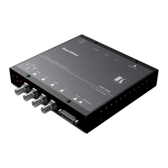
VP-792 SYSTEM DESCRIPTION 2.1. Product Overview VP-792 is designed to accept the following input signals: YPbPr or RGBS SD and ED and HD component video via 3 or 4 BNC connectors VGA analog (computer interface) via 15HDD DVI (Digital Visual Interface) via DVI-I (only the digital part is implemented on this connector), HDMI is supported via a HDMI/DVI adapter. -
Page 10: Display Output
2.2.5. Display Output A DVI-I connector is provided which will support DVI outputs as well as HDMI 1.3 with 36-bit video and HD audio formats when connected to a suitable HDMI 1.3 receiver. When the input signal has HDCP encryption, the DVI-D output connector will carry a similarly HDCP encrypted signal. When an HDCP encrypted signal is input, but the display device does not support HDCP, the output image will turn black and a message indicating HDCP Signal will come up to indicate this. -
Page 11: Vp-792 Control
VP-792 CONTROL 3.1. Menu Tree Level Level Level Level... -
Page 16: Introduction
3.2. Introduction The VP-792 units have the input connectors on one side of the housing and the output connector and communication ports on the opposite side. The keypad for controlling VP-792 is located on the input connectors side. The active input is indicated by their corresponding triangles lit green. - Page 17 A factory reset can also be applied when pressing the factory reset key combination at power up. The keys have to be kept pressed for about 10 seconds until the RGB(S) input LEDs stop flashing. If the keys are released during that 10 seconds period the system will get into Updater mode (see section 5) since the Menu key is part of this key combination.
-
Page 18: Main Menu
The list of inputs are: Component, VGA, DVI and Test Pattern. Test patterns can be generated by VP-792 without needing an input connected. When Test Pattern is selected as the input, the required test pattern can be chosen with the menu navigation up and down keys when the menu system has been exited, or it can be selected in Menu>System>Input Config>Test... -
Page 19: Location
3.5.2. Location Settings: Front Tabletop, Front Ceiling, Rear Tabletop, Rear Ceiling The image can be flipped to accommodate different projection scenarios as well as screens mounted upside down. 3.5.3. Optimize for Display Settings: DVI forced, Optimized, DVI/HDMI Internally, the display interface processes data at a full ten bits per color. The color depth on the DVI-D output is determined by the supported standard of the attached monitor or device when set to DVI/HDMI. -
Page 20: I/O Lock
Otherwise it is displayed at 50Hz. A 25Hz input mode is output at twice the frame rate 50Hz. An exception to the 24 and 25Hz input mode treatment is if the output resolution is set to 480i or 480p. 480i and 480p are always run at 60Hz output rate. 50Hz input modes are displayed at 50Hz output rate. -
Page 21: Color
3.6. Color This menu contains adjustments associated with setting up inputs to the unit. Use the Up and Down keys to scroll to the required item and press the Menu key. 3.6.1. Black-Level Offset Available Settings: 0 IRE, 7.5 IRE Used to select 7.5 IRE black level set-up adjustment. -
Page 22: Geometry
16:9 screen. With PC application activated the VP-792 communicates with the PC tool Warp Generator. Warp Generator allows you to define an arbitrary screen in live operation by projecting a grid on the surface and move the grid points to get a rectangular output. -
Page 23: Aspect Ratio
Crop preserves the aspect ratio and scales the image to fit the screen. Dependant on the aspect ratio of the panel either the top and bottom or right and left areas of the image are cropped. Anamorphic scales the input image such that it is displayed with a 16:9 aspect ratio when displayed on the screen. -
Page 24: Enhancement
3.8. Enhancement The enhancement menu provides image enhancement functions. Note that the enhancement settings apply to video input signals only, not computer graphics signals. 3.8.1. Sharpness Available settings: -50 to 50 in steps of 1 Control of the sharpening enhancement filters' levels. These are peaking filters to improve high- frequency response. -
Page 25: System
The DDC can be taken off line. When setting HDCP Input to OFF VP-792 pretends to be non HDCP compliant forcing the source to not encrypt data which is not copy protected. -
Page 26: Display Mode
By default VP-792 is in auto frame rate switching and I/O lock mode. In these modes the output of the scaler is forced to adopt the sync timings of the input signal... -
Page 27: Factory Defaults
Factory Defaults This button let you restore all settings to the default values of the VP-792, thus, provide a means to get back to a known (good) system state. A requestor will come up and ask to confirm prior to actual... -
Page 28: Multiple Unit
When using the Auto Zoom function - Each VP-792 unit gets the same graphics or video input signal through a distribution amplifier. The VP-792 unit cuts out and resizes the image to display the part of the image assigned to the corresponding screen. -
Page 29: Blend Curve Type
Custom Alpha Map menu item becomes available. Custom alpha maps can be uploaded through the Web or remote control API interface of VP-792. The map can be switched ON and OFF. The map is combined with the Align or S-curve map internally generated. If that is not wanted Blend Curve Type has to be set to OFF. -
Page 30: Remote Control Web Server
No extra software needs to be installed on a PC. The PC Web browser is used as the graphical user interface for all control items. To connect to the VP-792 the TCP/IP address of the unit has to be entered into the address list box of the Web browser in the following format http://xxx.xxx.xxx.xxx. The TCP/IP address assigned to VP-792 can be found in the System>Network Settings menu. -
Page 31: Software Operation
Test patterns can be created and stored on the PC. Four such custom test patterns can be uploaded to and stored by the VP-792 unit. Each of the test patterns in the four slots can be deleted and replaced by another test pattern. - Page 32 // 000008 3F FF FF FF 3F FF FF FF (beginning of first line) // ... // 000A08 3F FF FF FF 3F FF FF FF (beginning of second line) // ... // 2ED608 3F FF FF FF 3F FF FF FF (beginning of last line) // s = CEILING(1920 /3 ) * 4 * 1200 = 3072000 bytes...
-
Page 33: Firmware Update
5.1. Introduction VP-792 has a USB port which allows a PC connection. With the Kramer PC Updater tool new firmware can be installed on VP-792 for feature upgrades and bug fixes. The latest firmware version for your processor is published on our Website. Save the file to your computer. -
Page 34: Environmental And Emc
6.4. PAT Testing Earth continuity testing under PAT regulations shall be done to the VP-792 with 8A or 10A only. A test with 25A may damage the unit. In fact, VP-792 is IT equipment and the IEE Code of Practise to check earth continuity suggests an alternative 20-200mA test. - Page 35 For the latest information on our products and a list of Kramer distributors, visit our Web site where updates to this user manual may be found. We welcome your questions, comments, and feedback. SAFETY WARNING Disconnect the unit from the power...
Need help?
Do you have a question about the VP-792 and is the answer not in the manual?
Questions and answers