Table of Contents
Advertisement
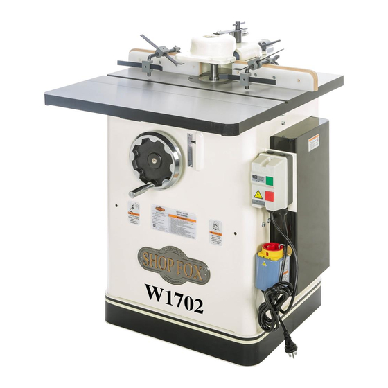
MODEL W1702
3 HP SHAPER
INSTRUCTION MANUAL
Phone: 1-360-734-3482 • On-Line Technical Support: tech-support@shopfox.biz
COPYRIGHT © SEPTEMBER, 2003 BY WOODSTOCK INTERNATIONAL, INC.
WARNING: NO PORTION OF THIS MANUAL MAY BE REPRODUCED IN ANY SHAPE OR FORM WITHOUT
THE WRITTEN APPROVAL OF WOODSTOCK INTERNATIONAL, INC.
Printed in Taiwan
Advertisement
Table of Contents

Related Manuals for Woodstock w1702


Summary of Contents for Woodstock w1702
-
Page 1: Instruction Manual
MODEL W1702 3 HP SHAPER INSTRUCTION MANUAL Phone: 1-360-734-3482 • On-Line Technical Support: tech-support@shopfox.biz COPYRIGHT © SEPTEMBER, 2003 BY WOODSTOCK INTERNATIONAL, INC. WARNING: NO PORTION OF THIS MANUAL MAY BE REPRODUCED IN ANY SHAPE OR FORM WITHOUT THE WRITTEN APPROVAL OF WOODSTOCK INTERNATIONAL, INC. - Page 2 WARNING Some dust created by power sanding, sawing, grinding, drilling, and other construction activities contains chemicals known to the State of California to cause cancer, birth defects or other reproductive harm. Some examples of these chemicals are: • Lead from lead-based paints. •...
-
Page 3: Table Of Contents
INTRODUCTION ...2 About Your New Shaper ...2 Woodstock Service and Support ...2 Warranty and Returns...3 Specifications ...3 SAFETY ...4 Standard Safety Instructions...4 Additional Safety Instructions for Shapers ...6 Avoiding Potential Injuries ...7 ELECTRICAL ...8 220V Operation...8 Extension Cords ...8 Grounding ...8 ASSEMBLY ...9 Unpacking ...9 Inventory...9... -
Page 4: Introduction
Close attention to engineering detail, ruggedly built parts, and a rigid quality control program assure safe and reliable operation. The Model W1702 features a 3 HP, 220V single-phase motor with forward/reverse spindle control. Also included are a heavy-duty miter gauge, fence with safety guard, cast iron handwheel, large precision ground cast iron table, and all ball bearing construction. -
Page 5: Warranty And Returns
Warranty and Returns Woodstock International, Inc. warrants all and materials for a period of 2 years from the date of original purchase by the original owner. This warranty does not apply to defects due directly or indirectly to misuse, abuse, negligence or accidents, lack of maintenance, or to repairs or alterations made or specifically authorized by anyone other than Woodstock International, Inc. -
Page 6: Safety
READ MANUAL BEFORE OPERATING MACHINE. FAILURE TO FOLLOW INSTRUCTIONS BELOW WILL RESULT IN PERSONAL INJURY. Indicates an imminently hazardous situation which, if not avoided, WILL result in death or serious injury. Indicates a potentially hazardous situation which, if not avoided, COULD result in death or serious injury. - Page 7 12. DO NOT force tool. The machine will do a safer and better job at the rate for which it was designed. 13. Use correct tool. DO NOT force machine or attachment to do a job for which it was not designed. 14.
-
Page 8: Additional Safety Instructions For Shapers
Additional Safety Instructions for Shapers READ and understand this entire instruction manual before using this machine. Serious personal injury may occur if safety and operational information is understood followed. DO NOT risk your safety by not reading! 1. Never place your hands within 12 inches of the cutters. Never pass your hands directly over or in front of the cutter. -
Page 9: Avoiding Potential Injuries
Avoiding Potential Injuries NOTE: Guard Removed for Clarity. Always Use Guard. SHOP FOX SHOP FOX Figure 1. Use a ® Featherboard as Figure 4. Use ® BOARD BUDDIES ® anti-kick back protection. holding down the workpiece. NOTE: Guard Removed for Clarity. Always Use Guard. SHOP FOX SHOP FOX Figure 5. -
Page 10: Electrical
220V Operation SHOP FOX ® Model W1702 Shaper 220 volt motor draws approximately 18 amps. Purchase a NEMA-style L6-20 plug and receptacle for the power supply circuit connection. Since other machines may be using the same circuit, make sure the circuit, circuit breaker, or fuse can carry a 20 amp load. -
Page 11: Assembly
Figure 9. Shaper unit. Figure 10. Layout of components. ASSEMBLY Unpacking The Model W1702 is carefully packed. However, if it is damaged or is missing any parts, please contact Woodstock International Service and assistance Support at 1-360-734-3482 or send e-mail to: tech-support@shopfox.biz. -
Page 12: Initial Cleaning
While the main components of the Model W1702 are assembled at the factory, some assembly is required including shop preparation. The following is the recommended sequence best suited for final installation and assembly. -
Page 13: Dust Collection
• Machine Mobility: Use the Model D2057 SHOP FOX you can make the most out of your shop space by moving the Model W1702 3 HP Shaper out of the way when not in use. Contact your and availability. •... -
Page 14: Fence Facing
Fence Facing Fence facing can be custom made for special needs—for example, mounting a hold-down SHOP FOX roller systems like the W1105 Green BOARD BUDDIES ® To install the fence facing, do these steps: 1. Using ⁄ "-20 x ⁄ "... -
Page 15: Hold-Downs
Figure 15. Assembling hold-down mechanism. Figure 16. Assembled hold-down mechanism. Figure 17. Attaching the crank handle. Hold-Downs The hold-downs hold the workpiece against the fence and the table. NOTE: Remove the hold- down assembly when not in use. Hold-down To install the hold-downs, do these steps: Bracket 1. -
Page 16: Spindle
Spindle The Model W1702 comes with ⁄ shaper spindles. Also available is a Model D3392 Optional Router Bit Spindle. It is very important that any spindle you use, is seated securely into the shaper so that safety is maintained. To install the shaper spindle or router bit... - Page 17 Figure 20. Threading drawbar nut onto drawbar. Figure 21. Tightening the drawbar nut onto the end of the drawbar. 6. Thread the tapered drawbar nut onto the end of the drawbar under the table, and make sure that the taper side of the nut is facing upward as shown in Figure 20.
-
Page 18: Adjustments
Fence Positioning The two fence faces are independently adjustable to allow for different shaping tasks. The fence faces can be set at different positions to remove material from the entire edge of the wood stock or the same position to allow the shaping of part of the edge. -
Page 19: Fence Alignment
Figure 23. Use straightedge to check fence. Fence Alignment Before shaping, check that the two fence faces are parallel. To align the fences so they are parallel with each other, do these steps: 1. Get a quality straightedge that is long enough to span the entire length of the fence assembly. -
Page 20: Table Inserts
Table Inserts The table inserts are necessary for the safe operation of the shaper. Two inserts are provided allowing for three different opening sizes to be achieved. Use the smallest-size opening for a cutter to reduce wood chips falling into the machine, which could cause flying debris. -
Page 21: Pulley Alignment
Figure 26. Use straightedge to check V-belts. Figure 27. Loosening motor mount bolts. Figure 28. Loosening spindle cartridge bolt. Pulley Alignment Pulley alignment performance of your shaper. If the pulleys are just slightly out of alignment, the shaper may suffer from power loss as well as decreased V- belt life. -
Page 22: Spindle Rpm
Spindle RPM This shaper spindle can be run at 7,000 or 10,000 RPM. The speed is changed by the placement of the V-belt as shown in Figure 29. Choose Spindle RPM: Always follow cutter recommendations; however, if not available use these general specifications to help select spindle and RPM. -
Page 23: Spindle Slide And Gib
Spindle Elevation Lock Housing Spindle Slide Gib Adjustment Setscrew Figure 31. Spindle slide, elevation housing, spindle lock, and gib adjustment setscrews. NOTICE If the handwheel is adjusted so the spindle slide completely moves to the lowest position, and the handwheel is forced further past the stop, the gib can fall out of place and bind the spindle slide on future upward travel. -
Page 24: Operations
Start Up Once assembly is complete and adjustments have been made, the shaper is ready for start up. Always pay attention to any unusual noises and vibrations on every start up, as well as make sure the shaper operates as intended. MAKE SURE that the fence, any accessories, Jigs, spindle, cutter, or router bit adapter... -
Page 25: Cutter Direction
Cutter Direction The Model W1702 is capable of operating in two directions by use of a forward and reverse switch as shown in Figure 32. It is very important that the workpiece be fed against the direction of the cutter rotation. -
Page 26: Cutter Installation
Cutter Installation Always follow cutter recommendations; however, if not available use the list below with your particular cutting needs in mind to help select the correct cutter, spindle, and RPM. Then install your cutter as outlined. a) Choose Cutter Profile and Cutter: To help select the correct cutter, you can go online to select your cutter, bushings, and rub collars. - Page 27 Figure 36. Spindle washer placement. Figure 37. Collar or spacer placement. Figure 38. Spindle nut placement. UNPLUG cord before you do any assembly, adjustments, or maintenance tasks! Otherwise, personal injury to you or others may occur! To install a cutter, do these steps: 1.
-
Page 28: Setting Spindle Height
6. Tighten down the nut and locknut with an open-end wrench while holding the top of the spindle with the provided spindle wrench as shown in Figure 39. 7. Make sure the cutter will rotate in the correct direction. NOTICE Always check the direction of the cutterhead before performing a shaper operation. -
Page 29: Straight Shaping
Fence Mount Lock Handle Adjustment Knob Figure 42. Fence mount lock handle. Figure 43. Fence setup for jointing-type operations (Guard Not Shown For Clarity). Straight Shaping Because the shaper fence is independently adjustable, you can set up the shaper to cut part or all of the workpiece edge. - Page 30 ALWAYS use the aid of a jig when shaping small or narrow workpieces. A jig will reduce the chance of your hands coming into contact with the cutters. Failure to follow this warning may result in serious personal injury. To set up the fence for partial edge removal or profiling an edge, do these steps: 1.
-
Page 31: Rub Collars
Figure 46. Rub collar set. Figure 47. Rub collar mounted above cutter. Figure 48. Rub collar mounted between two cutters. NOT RECOMMENDED Figure 49. Rub collar mounted below cutter. Rub Collars When shaping workpieces that have irregular shapes, rub collars are a necessity. There are two types of rub collars: solid and ball bearing. -
Page 32: Freehand Shaping
Freehand Shaping Freehand shaping is shaping without the aid of the miter slot or fence. The most dangerous part of shaping freehand is beginning the cut, where the cutter first contacts the workpiece. Often the workpiece will tend to jerk or kickback, catching the operator off guard. -
Page 33: Pattern Shaping
Figure 52. A piece of wood clamped to the table can serve as a make-shift starting pin (Guard not shown for clarity). Figure 53. Using a rub collar against a template. Pattern Shaping Sometimes the location of the starting pin holes will not always be in the safest position. -
Page 34: Table And Base
General Regular periodic maintenance on your Model W1702 Shaper will ensure performance. Make a habit of inspecting your shaper each time you use it. Check for the following conditions and repair or replace parts when necessary. Loose mounting bolts. Worn switch. -
Page 35: Troubleshooting
Troubleshooting -33-... - Page 36 General Information. The specifications, drawings, and photographs illustrated in this manual represent the Model W1702 3 HP Shaper as supplied when the manual was prepared. However, due to Woodstock International, Inc.’s...
-
Page 37: Wiring Diagram
Model W1702 220V Wiring Diagram -35-... -
Page 38: Parts Breakdowns And Parts Lists
-36-... - Page 39 " SCALE PHLP HD SCR ⁄ "-18 X 1 ⁄ " POWER CORD, 3 WIRE ADJUSTMENT TUBE COLOR STRIPE LABEL (W1702) MOTOR POWER CORD, 5 WIRE SELF TAPPING SCREW FLAT WASHER ⁄ " FLAT WASHER ⁄ " FLAT WASHER ⁄...
- Page 40 -38-...
-
Page 41: Parts
PART # DESCRIPTION 101 X1702101 HANDLE 102 X1702102 HANDWHEEL 103 XPB09 HEX BOLT ⁄ "-18 x 104 XPSS15 SETSCREW ⁄ "-16 x 105 XPSS08 SETSCREW ⁄ "-18 x 106 X1702106 COLLAR 107 XPSB07 CAP SCREW ⁄ 108 X1702108 SHAFT MOUNT 109 X1702109 BUSHING 111 X1702111... - Page 42 -40-...
- Page 43 REF# PART # DESCRIPTION XPR15M EXT RETAINING RING 30mm X1702204 SPINDLE CARTRIDGE XPK20M KEY 5 x 5 x 15mm XP6205 BEARING 6205 ZZ X170207 INT RETAINING RING 25mm X170209 BEARING HOUSING XPR14M EXT RETAINING RING 70mm X1702211 PULLEY X1702212 TOOTHED WASHER X1702213 SPANNER NUT X1702214...
- Page 44 -42-...
- Page 45 PART # DESCRIPTION 301 XPSS02 SETSCREW ⁄ "-18 x 302 X1702302 SHAFT MOUNT 303 XPW02 LOCK WASHER 304 XPB18 HEX BOLT ⁄ "-16 x 1" 305 X1702305 EXTENSION BRACKET 306 X1702306 LOCK KNOB W/SHAFT 309 X1702309 SHAFT PART # ⁄ "...
- Page 46 -44-...
- Page 47 PART# DESCRIPTION 603 X1702 603 MITER GAUGE BODY 604 X1702 604 MITER BAR 605 X1702 605 SPECIAL WASHER 606 XPFH19 FLAT HEAD SCREW 607 XPNO7 HEX NUT 10-24 608 XPSS32 SETSCREW 10-24 X 609 XPSS29 SETSCREW 10-24 X PART# 610 X1702610 611 X1702611 612 X1702612 613 X1702613...
- Page 48 PART # DESCRIPTION 401 X1702401 HOLD-DOWN BAR 402 X1702402 HOLD-DOWN 403 X1702403 BRACKET, HOLD-DOWN 404 XPSS02 SETSCREW ⁄ " - 18 x -46- ⁄ "...
-
Page 49: Shaper Accessories
Shaper Accessories The following shaper accessories may be available through your local Woodstock International Inc. Dealer. If you do not have a dealer in your area, these products are also available through online dealers. Please call or e-mail Woodstock International Inc. Customer Service to get a current listing of dealers at: 1-800 840-8420 or at sales@woodstockint.com. - Page 50 Shaper Accessories The D1700 Woodstock Moulding Head and available knives let you cut many profiles for your projects. This system uses a wide variety of precision-ground cutter patterns for use in a specially-designed CNC-machined, aircraft aluminum cutterhead. The 2" moulding head accepts all 2"...
-
Page 51: Your Notes
Your Notes... - Page 52 Your Notes...
-
Page 53: Warranty Card
Name __________________________________________________________________________________________ Street __________________________________________________________________________________________ City ____________________________________________________________________State________Zip_________ Phone Number_______________________E-Mail_________________________________FAX___________________ MODEL # _____________________ SERIAL #___________________________________________________________ The following information is given on a voluntary basis and is strictly confidential. Where did you purchase your SHOP FOX ® _________________________________________________________ How did you first learn about us? ___Advertisement ___Friend ___Mail order Catalog... - Page 54 FOLD ALONG DOTTED LINE FOLD ALONG DOTTED LINE WOODSTOCK INTERNATIONAL, INC. P.O. BOX 2309 BELLINGHAM, WA 98227-2309 TAPE ALONG EDGES--PLEASE DO NOT STAPLE Place Stamp Here...
Need help?
Do you have a question about the w1702 and is the answer not in the manual?
Questions and answers