Table of Contents
Advertisement
Quick Links
Advertisement
Table of Contents
Troubleshooting

Subscribe to Our Youtube Channel
Related Manuals for Woodstock SHOP FOX W1814


Summary of Contents for Woodstock SHOP FOX W1814
-
Page 3: Table Of Contents
INTRODUCTION ........2 MAINTENANCE ........26 Woodstock Technical Support ....2 General .......... 26 Machine Specifications ......3 Cleaning ......... 26 Controls and Features ......4 V-Belts ........... 26 Lubrication ........26 SAFETY ..........5 Standard Safety Instructions ....5 SERVICE .......... -
Page 4: Safety
Close attention to detail, ruggedly built parts and a rigid quality control program assure safe and reliable operation. Woodstock International, Inc. is committed to customer satisfaction. Our intent with this manual is to include the basic information for safety, setup, operation, maintenance, and service of this product. - Page 5 Phone #: (360) 734-3482 • Online Tech Support: tech-support@shopfox.biz • Web: www.shopfox.biz Type ........................Universal Horsepower ......................... 2 HP Voltage ........................110V Prewired ........................110V Phase ........................Single Amps .......................... 12A Speed ........................20,000 RPM Cycle ........................60 Hz Number Of Speeds ......................1 Power Transfer ....................
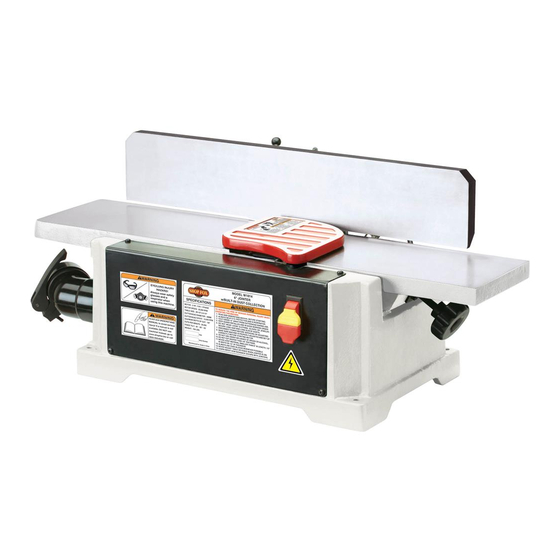
- Page 6 2. W1814 identification — back view. 1. W1814 identification — front view. Fence Bracket Assembly Outfeed Table Fence Tilting Handle Cutterhead Guard Fence Sliding Handle Fence Infeed Table Depth of Cut Adjusting Knob ON/OFF Switch Dust Collection Chute Dust Collection Bag Push Blocks (not shown)
- Page 7 Indicates an imminently hazardous situation which, if not avoided, WILL result in death or serious injury. Indicates a potentially hazardous situation which, if not avoided, COULD result in death or serious injury. Indicates a potentially hazardous situation which, if not avoided, MAY result in minor or moderate injury.
- Page 8 Turn power and allow all moving parts to come to a complete stop before leaving machine unattended. DO NOT use machinery in damp, wet locations, or where any flammable or noxious fumes may exist. Clutter and dark shadows may cause accidents. Undersized cords over- heat and lose power.
- Page 9 “Kickback” is when the workpiece is thrown off the jointer table by the force of the cutterhead. Always use push blocks and safety glasses to reduce the likelihood of injury from “kickback.” If you do not understand what kickback is, or how it occurs, DO NOT operate this machine.
- Page 10 Correct operator and workpiece position, guard is in place, and push blocks are being used. Never surface plane without push Never stand directly behind the blocks! workpiece! Never joint end grain! Never plane/edge-joint with the guard removed!
-
Page 11: Electrical
The Model W1814 is wired for 110V operation. We recommend connecting this machine to a dedicated 8 5-15 plug and receptacle. circuit with a verified ground, using the circuit size below as a minimum. Never replace a circuit breaker with one of higher amperage without consulting a qualified electrician to ensure compliance with wiring codes. - Page 12 Model W1814 has been carefully pack- aged for safe transporting. If you notice the machine has been damaged, please contact your authorized dealer immediately. The following items are needed, but not included, to set up your machine: • People for Lifting ......As Needed •...
- Page 13 The following is a description of the items shipped with ® Model W1814. 8 & 9) Jointer Bed Assembly ........1 Fence ............1 Dust Collection Bag ........1 Dust Collection Bag Clamp .......1 Dust Chute ..........1 Fence Support ..........1 Locking Plate Assembly ........1 Fence Sliding Handle ........1 Fence Bracket Assembly ........1 Fence Tilting Handle ........1...
- Page 14 The table and other unpainted parts of your Consider existing and jointer are coated with a waxy grease that anticipated needs, size of material to be protects them from corrosion during shipment. processed through the machine, and space for auxiliary stands, work tables or other Clean this grease off with a solvent cleaner or machinery when establishing a location for citrus-based degreaser.
- Page 15 The Model W1814 MUST be securely fastened to a workbench before it can be safely operated. An unsecure jointer may shift during operation and cause serious personal injury. The strongest bench mounting option is a "Through Mount" where holes are drilled all the way through the workbench, and hex bolts, washers, and hex nuts are used to secure the jointer to the workbench.
- Page 16 DISCONNECT JOINTER FROM POWER SOURCE! Cap Screws Use two of the included cap screws and lock washers to attach the fence support to the jointer bed, as shown in Fence Jointer Bed Support 12. Attaching the fence support to the bed assembly. Insert the locking plate assembly into the fence Locking Plate support, positioning it so the two pins are against...
- Page 17 Use the remaining four cap screws and washers to attach the fence to the fence bracket assembly, as Bracket shown in Assembly Screws Fence 15. Attaching the fence to the fence bracket assembly. Slide the fence bracket assembly over and onto the dovetail of the support and locking plate, as shown Fence Bracket...
-
Page 18: Setup
Install the fence tilting handle by screwing the handle shaft into the bracket assembly, as shown in Outward Stop Bracket Fence Tilting The knives MUST be level with the outfeed table when Assembly Handle Shaft they are at top dead center (their highest point during rotation) or the workpiece cannot be safely fed across the Installing the fence tilting jointer. -
Page 19: Dust Collection
Loosen the two jack screws, then, using a scrap wood block, push the knife blade down until both ends are sightly below the straightedge. Using the 4mm hex wrench, turn each jack screw clockwise ⁄ of a turn at a time until each end of the knife (see 22) touches the straightedge evenly. -
Page 20: Test Run
Once the assembly is complete, test run your machine to make sure it runs properly. If, during the test run, you cannot easily locate the source of an unusual noise or vibration, stop using the machine immediately, then review the If you still cannot remedy a problem, contact our Tech Support at (360) 734-3482 for assistance. -
Page 21: Operations
The Model W1814 will perform many types of operations that are beyond the scope of this manual. Many of these operations can be dangerous or deadly if performed incorrectly. The instructions in this section are written with the understanding that the operator has the necessary knowl- edge and skills to operate this machine. -
Page 22: Basic Controls
This section covers the basic parts and controls used during routine operations. Refer to basic parts and control locations. This paddle switch starts and stops the cutterhead rotation. The yellow part of the switch is a safety device. When you remove this part, the switch locks in position. -
Page 23: Surface Planing
• Injury to the operator or damage to the workpiece can occur if the knots become dislodged during the cutting operation. • Cutting against the grain increases the likelihood of stock kickback, as well as tear-out on the workpiece. Correct setting for grain •... - Page 24 r: The concave face of the workpiece is surface planed flat with the jointer : The opposite Surface plane on the jointer. face of the workpiece is surface planed flat with a thickness planer ( : The concave edge of the workpiece is jointed flat with the jointer ( This Side Previously Surface Planed...
- Page 25 The purpose of surface planing on the jointer is to make one flat face on a piece of stock (see & ) to prepare it for surface planing on a thickness planer. Typical surface planing operation. Read and understand , beginning on Make sure your stock has been inspected for dangerous conditions as described in the instructions, beginning...
- Page 26 The purpose of edge jointing is to produce a finished, flat-edged surface (see & ) that is suitable for joinery or finishing. It is also a necessary step when squaring rough or warped stock. Typical edge jointing operation. Read and understand , beginning on Make sure your stock has been inspected for danger- ous conditions as described in the...
-
Page 27: Bevel Cutting
The purpose of bevel cutting is to cut a specific angle into the edge of a workpiece (see & The Model W1814 has preset fence stops at 45˚ inward, 90˚, and 45˚ outward (135˚). If your situation requires a different angle, the preset fence stops can be easily adjusted for your needs. -
Page 28: Maintenance
For optimum performance from your machine, follow this maintenance schedule and refer to any specific instructions given in this section. • Vacuum all dust on and around the machine. • Empty debris from the dust collection bag. DO NOT use the jointer if debris obstructs the flow of material into the bag. -
Page 29: Service
If you require additional machine service not included in this section, please contact Woodstock International Technical Support at (360) 734-3482 or send e-mail to: This section provides instructions for setting the fence stops precisely at 45°... - Page 30 Loosen the fence tilting handle, bring the fence to 90º with the square set against the fence, then tighten the handle. Loosen the jam nut (located at the rear of the limit block shaft). Using a screwdriver, turn the limit block set screw until the limit block shaft hits the fence.
- Page 31 Use two 8mm wrenches to tighten the hex nut on the inward stop as you hold the stop in place. Put the limit block back, bring the fence back to 90º and tighten the tilting handle. DISCONNECT JOINTER FROM POWER SOURCE! Loosen the fence tilting handle, remove the limit block and set it aside.
- Page 32 Your W1814 uses belts to drive both the cutterhead and the dust collection impeller. When these belts are not tensioned correctly, misaligned, or damaged, your jointer Motor Mount Screws will not function properly. The part number for the replacement drive belt is #X1814170;...
-
Page 33: Troubleshooting
This jointer has a universal motor that uses carbon brushes, which are considered wear-items. Refer to the troubleshooting guide to determine if the motor brushes must be replaced. You can order a new brush kit (two brush assemblies) by calling customer service and ordering part #X1814124-1. DISCONNECT JOINTER FROM POWER SOURCE. - Page 34 -32-...
- Page 35 This section covers the most common problems and corrections with this type of machine. Machine does not start or 1. Safety key removed from ON/OFF 1. Replace safety key. a breaker trips. switch. 2. Plug/receptacle is at fault or wired 2.
- Page 36 1. Knives set too high. 1. Set the knives just even with the outfeed table when Excessive snipe (gouge in the end of the board that they're at TDC (top dead center). is uneven with the rest of 2. Operator pushing down on trailing 2.
- Page 37 -35-...
- Page 38 PART # DESCRIPTION PART # DESCRIPTION X1814101 BASE X1814150 PUSH BLOCK X1814102 FENCE X1814151 PADDLE SWITCH X1814103 FENCE PLATE XP6000ZZ BALL BEARING 6000ZZ X1814104 HANDLE XPSS01M SET SCREW M6-1 X 10 XPW01M FLAT WASHER 8MM XPSB26M CAP SCREW M6-1 X 12 X1814106 RIGHT LINK XPLW03M...
- Page 39 Safety labels warn about machine hazards and ways to prevent injury. The owner of this machine MUST maintain the original location and readability of the labels on the machine. If any label is removed or becomes unreadable, REPLACE that label before using the machine again. PART # DESCRIPTION PART #...
- Page 40 -38-...
- Page 41 Name ___________________________________________________________________________________ Street __________________________________________________________________________________ City _________________________ State ___________________________Zip ________________________ Phone # ______________________ Email___________________________Invoice # ___________________ Model #_________Serial #______________Dealer Name__________________Purchase Date___________ How did you learn about us? _____ Advertisement _____ Friend ____ Local Store _____ Mail Order Catalog _____ Website ____ Other: How long have you been a woodworker/metalworker? _____ 0-2 Years _____ 2-8 Years...
- Page 42 FOLD ALONG DOTTED LINE Place Stamp Here FOLD ALONG DOTTED LINE TAPE ALONG EDGES--PLEASE DO NOT STAPLE...
Need help?
Do you have a question about the SHOP FOX W1814 and is the answer not in the manual?
Questions and answers