Table of Contents
Advertisement
Quick Links
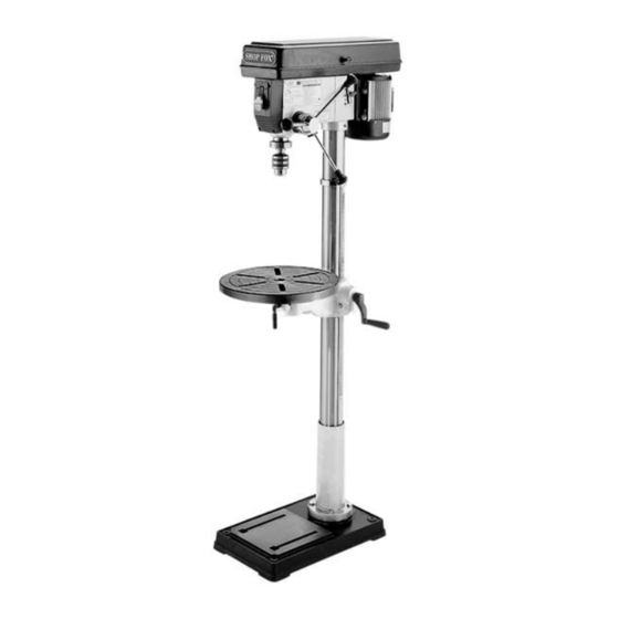
MODEL W1680
17" DRILL PRESS
INSTRUCTION MANUAL
Phone: 1-800-840-8420 • On-Line Technical Support: tech-support@woodstockint.com
COPYRIGHT © 2000 BY WOODSTOCK INTERNATIONAL, INC.
WARNING: NO PORTION OF THIS MANUAL MAY BE REPRODUCED IN ANY SHAPE OR FORM WITHOUT
THE WRITTEN APPROVAL OF WOODSTOCK INTERNATIONAL, INC.
Printed in China
Advertisement
Table of Contents

Subscribe to Our Youtube Channel
Related Manuals for Woodstock G9974


Summary of Contents for Woodstock G9974
-
Page 1: Instruction Manual
MODEL W1680 17" DRILL PRESS INSTRUCTION MANUAL Phone: 1-800-840-8420 • On-Line Technical Support: tech-support@woodstockint.com COPYRIGHT © 2000 BY WOODSTOCK INTERNATIONAL, INC. WARNING: NO PORTION OF THIS MANUAL MAY BE REPRODUCED IN ANY SHAPE OR FORM WITHOUT THE WRITTEN APPROVAL OF WOODSTOCK INTERNATIONAL, INC. -
Page 2: Table Of Contents
Table Of Contents INTRODUCTION ...2 ABOUT YOUR NEW DRILL PRESS ...2 WOODSTOCK SERVICE AND SUPPORT ...2 WARRANTY AND RETURNS ...3 MACHINE SPECIFICATIONS ...3 SAFETY FIRST! ...4 STANDARD SAFETY INSTRUCTIONS ...4-5 DRILL PRESS SAFETY ...5 ELECTRICAL REQUIREMENTS ...6 AVOIDING POTENTIAL INJURIES ...7 ASSEMBLY INSTRUCTIONS ...8... -
Page 3: Introduction
The Model W1680 Drill Press is capable of a wide variety of drilling operations in metal, wood and plas- tic. The tilting table allows drilling angles from 90˚ to 0˚. Precision ground spindle, table, base and col- umn ensure dependable accuracy. -
Page 4: Warranty And Returns
WARRANTY AND RETURNS Woodstock International, Inc. warrants all SHOP FOX ship and materials for a period of 2 years from the date of original purchase by the original owner. This warranty does not apply to defects due directly or indirectly to misuse, abuse, negligence or accidents, lack of maintenance, or to repair or alterations made or specifically authorized by anyone other than Woodstock International, Inc. -
Page 5: Safety First
SAFETY FIRST! READ MANUAL BEFORE OPERATING MACHINE FAILURE TO FOLLOW INSTRUCTIONS BELOW WILL RESULT IN PERSONAL INJURY Indicates an imminently hazardous situation which, if not avoided, WILL result in death or serious injury. Indicates a potentially hazardous situation which, if not avoided, COULD result in death or serious injury. -
Page 6: Drill Press Safety
Additional Safety Instructions For Drill Presses Always operate your drill press at speeds that are appropriate for the drill bit size and the mate- rial that you are drilling. Feed the drill bit evenly into the workpiece. Back the bit out of deep holes and clear the chips with a brush after you have turned the machine off. -
Page 7: Electrical Requirements
® W1680 Drill Press is supplied for 110 volt operation, only. The motor supplied with your new drill press is rated at 1 horse power and will draw approximately 10 amps. When choosing an outlet for this machine, con- sider using one with a 15 amp circuit breaker or fuse. -
Page 8: Avoiding Potential Injuries
AVOIDING POTENTIAL INJURIES Figure 2. Never drill, holding workpiece by hand. Figure 3. Keep fingers away from spinning tool. Fig. 4. Remove Switch Safety Key when not in use. Figure 5. Unplug machine when changing bulbs. -
Page 9: Assembly Instructions
6. Drill Chuck and Key 7. Drill Chuck Arbor 8. Spindle Handles (3) ® 9. Allen Wrenches (2) ® W1680 Drill Press. It is rec- 10.Wedge 11.Hex Head Bolts (4) 12.Belt Cover Knob and Screw 13.Handle 14.Pinion Gear 15.Lock Handles (2) 16.Rack... -
Page 10: Base And Column
Figure 7. Secure base to floor. Figure 8. Secure base to plywood. ® W1680 Drill Press are assembled at the factory, some ⁄ " open end wrench, a rubber or wooden mallet and a 5mm Allen Base/Column The W1680 Drill Press is a floor model and... -
Page 11: Table Support
Table Support 1. Thread the 12mm table lock handle 3 turns into the table support bracket. 2. Insert the pinion into the hole on the side of the table support bracket from the inside, starting with the pinion shaft. Figure 9. Align setscrew in crank handle with flat, Figure 10, on pinion shaft and secure using the 3mm Allen... -
Page 12: Table Support
Figure 12. Bottom of rack in position. Figure 13. Inside bevel in the correct position. Table Support, Cont. 4. Slide the table support bracket onto the col- umn while holding the rack in place. Allow the bracket to go down until the bottom of the rack contacts the shoulder on the col- umn support. -
Page 13: Headstock
2. Align the headstock directly over the foot of the base by using a plumb bob. Lay a mea- suring tape or ruler across the drill press base and find its center. Suspend the plumb line from the center of the headstock label and lower the bob until it is near the tape/ruler as in Figure 15. -
Page 14: Handles
Installing Light Bulb The Shop Fox ® 17" Drill Press is fitted with a light socket that accommodates standard sized bulbs. Use only bulbs that are “safety coated” and shatter resistant. The bulb will be exposed at the bottom of the head casting which helps with illumination. -
Page 15: Drill Chuck And Arbor
Drill Chuck and Arbor The drill chuck is attached to the drill spindle by means of a drill chuck arbor. Matched tapers on the arbor and the back of the chuck create an almost permanent assembly when properly joined. To assemble the drill chuck and mount it to the spindle, carefully follow the instructions below: Many of the solvents commonly used to... -
Page 16: Arbor Removal
Figure 20. Seating arbor into spindle. Figure 21. Inner and outer slots aligned. Figure 22. Using wedge to remove arbor. 4. Slide the arbor into the spindle socket while slowly rotating drill chuck. The socket has a rectangular pocket in which the tang (or flat portion of the arbor) fits into. -
Page 17: Adjustments
Unplug the drill press before changing speeds. The Drill Press has 12 speeds ranging from 140 to 3050 RPM. There is a speed chart located under the belt guard and one on the following page. Refer to these while reading these instructions. -
Page 18: Spindle Adjustments
Figure 26. Loosening collar lock knob. Figure 27. Actual stop depth being measured. Spindle Adjustments Your new drill press comes fitted with a depth stop for use when drilling. Follow the instruc- tions below for use. 1. Loosen the depth collar lock knob. Figure 2. -
Page 19: Table Adjustments
Table Adjustments The table can be adjusted for height, rotation and angle. Follow these instructions to adjust height: 1. Loosen the support bracket lock knob. Turn the table hand crank to lift or lower the table. Figure 28. 2. Always lock the support bracket in place before operating machine. -
Page 20: Operations
Pull the START paddle. Make sure that your finger is poised over the paddle, Figure 31, just in case there is a problem. The drill press should run smoothly, with little or no vibration or rubbing noises. Strange or unnatural noises... -
Page 21: Drill Changes
DO NOT investigate prob- lems or adjust the drill press while it is running. Wait until the machine is turned off, unplugged and all working parts have come to a complete stop before proceeding! Drill Bit Changes Care must be taken to secure the bit firmly in place. -
Page 22: Maintenance
Regular periodic maintenance on your Model W1680 Drill Press will ensure its optimum per- formance. Make a habit of inspecting your drill press each time you use it. Check for the fol- lowing conditions and repair or replace when necessary. -
Page 23: Closure
Trade journals, woodworking magazines, and your As with all power tools, there is danger asso- ciated with the Model W1680 Drill Press. Use the tool with respect and caution to lessen the possibility of mechanical damage or operator injury. -
Page 24: Wire Diagram
Your Notes: -23-... - Page 26 PART # DESCRIPTION X1680001 BASE XPB27M HEX BOLT M12-1.75 X 30 X1680003 RACK X1680004 COLUMN X1680005 TABLE BRACKET X1680006 HANDLE X1680007 SET SCREW X1680008 SHAFT X1680009 X1680010 X1680011 WASHER X1680012 BOLT X1680013 TABLE BOLT X1680014 TABLE ARM BRACKET X1680015 TABLE X1680016 CLAMP BOLT X1680017...
- Page 27 PART # DESCRIPTION X1680053 SLIDE BAR X1680054 SLIDE BAR X1680055 MOTOR BASE X1680056 WASHER 56A X1680056A SPRING WASHER X1680057 X1680058 MOTOR X1680059 MOTOR PULLEY X1680060 X1680061 SET SCREW X1680062 V-BELT X1680063 CENTER SHAFT XP6202 BALL BEARING 6202ZZ XP6202 BALL BEARING 6202ZZ X1680066 INTERNAL RETAINING RING X1680067...
- Page 28 ___Jointer ___Lathe ___Mortiser ___Other__________________________________________________ Which benchtop tools do you own? Check all that apply. ___1" x 42" Belt Sander ___5" - 8" Drill Press ___8" Table Saw ___8" - 10" Bandsaw ___Disc/Belt Sander ___Mini Jointer ___Other__________________________________________________ Which portable/hand held power tools do you own? Check all that apply.
- Page 29 FOLD ALONG DOTTED LINE FOLD ALONG DOTTED LINE WOODSTOCK INTERNATIONAL, INC. P.O. BOX 2309 BELLINGHAM, WA 98227-2309 TAPE ALONG EDGES--PLEASE DO NOT STAPLE Place Stamp Here...
Need help?
Do you have a question about the G9974 and is the answer not in the manual?
Questions and answers