Table of Contents
Advertisement
Advertisement
Table of Contents

Subscribe to Our Youtube Channel
Related Manuals for SecurityMan Mini-AirWatch4


Summary of Contents for SecurityMan Mini-AirWatch4
- Page 1 SecurityMan ® Mini-AirWatch4 Four 2.4GHz Wireless Color Camera Kit User Guide...
- Page 2 Limitation of Liability The liability of SecurityMan arising from this warranty and sale shall be limited to a refund of the purchase price. In no event shall SecurityMan be liable for costs of procurement of substitute products or services, or for any lost profits, or for any consequential, incidental, direct or indirect damages, however caused and on any theory of liability, arising from this warranty and sale.
- Page 3 1 feet away from any heart pacemaker. Radio waves might potentially influence heart pacemaker and lead to respiratory disturbance. DO NOT use this product for any illegal activities. SecurityMan shall not be responsible for any consequences of illegal conducts by users.
- Page 4 Conditions Please read the following messages to make sure whether your working envi- ronment is suitable. • Ensure there is enough space around the receiver for ventilation. • The temperature should be kept between –20˚C and 50˚C (-4F – 122˚F). The relative humidity should remain from 20% to 80%.
- Page 5 Important Information The user’s manual provides important information for customers to use their products properly, and avoid possible injuries and damages. The condition of being susceptible to harm or injury A careful attention to the probable effects of an act, in order that failure or harm may be avoided A notification or communication of a fact, claim, demand, or proceeding...
- Page 6 DO NOT cover the AC adapter when it is connected to power socket, place the adapter near heaters, and put it on the floor that is equipped with a heater. *The above-mentioned operation might cause fire or incidents. DO NOT use it on airplanes. Please abide by the airways provision.
- Page 7 DO NOT place or use the AC adapter on temperature sensitive materials. *The above practice might cause the plastic distortion, fading or sticking on the surface. DO NOT touch, shake or hold the aerial. *Touching, shaking or holding the aerial might influence the receiving of electromagnetic wave, and thereby influence the receiving effect.
- Page 8 DO NOT use the camera in complex envi- ronment. The obstruction of stumbling block will affect the electromagnetic wave and influence the receiving range. *Wall, tree and other stumbling block might absorb, reflect the electromagnetic wave and influence the receiving range. DO NOT use the camera in the places that are covered by metal.
-
Page 9: Table Of Contents
Contents Introduction Package Contents Technical Support Product Basics Setting up the Camera(s) Setting up the Receiver with TV/Monitor Installation Diagram Antenna Adjustment Using Channel Switch on the Receiver Using the Remote Control Remote Control buttons and functions Specification Troubleshooting... -
Page 10: Introduction
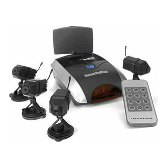
Introduction Thank you for purchasing Mini-AirWatch Wireless Camera Kit. It consists of 4 Color Video Cameras with built-in 2.4GHz Video Transmitter, and a Video Receiver unit which you connect to a TV anywhere in your home (up to 100ft. away from the camera). The Camera converts the video and audio signals into radio signals and transmits them to the Video Receiver. -
Page 11: Product Basics
Product Basics Camera Adjustable lens Antenna Camera Back Holes for Focus Adjustment Tool CH1 CH2 CH3 CH4 Bracket Dip-Switch Focus Adjustment Power Jack Tool Remote Control Channels Number Lock/ Unlock Key Channel Down Channel Circulator Setup Key CHANNEL REMOTE Battery Clip 9V Battery Connector (battery included) - Page 12 Receiver Back DC12V AUDIO/R AUDIO/L VIDEO/R Power Jack (DC 12V, 300mA) Video output (Yellow) Audio output Right (White) Audio output Left (Red) Receiver Front Antenna Channels switch/ circulator IR signal receiving LED channel window display Dip-Switch (Camera) To adjust the dip-switch channel for the camera, use a pointed object to set the dip-switch to desired channel on the back of the camera.
-
Page 13: Camera Back
Setting up the Camera(s) Set the camera to desired Dip-Switch Channel Place the camera(s) at desired location. Plug the power adapter or battery clip jack into the power jack at the back of the camera. Plug the power adapter to any AC outlet or plug a 9V battery to the battery clip. -
Page 14: Installation Diagram
Installation Diagram Camera 1 9V battery or 8V AC adapter Camera 2 9V battery or 8V AC adapter Camera 3 A / V Cable 9V battery or 8V AC adapter TV/ Monitor Camera 4 9V battery or 8V AC adapter WARNING: When using power adapter, make sure the voltage indica- tions on the adapters are compatible to the devices to avoid potential damages for incorrect usage of power. -
Page 15: Using Channel Switch On The Receiver
Using Channel Switch on the Receiver Channel Switch Press the Channel Switch ONCE, to change the channel correspon- ding to camera. You can view one camera at a time. > > > (Press Channel Switch button once, it will change from Ch1 to Ch2 on the TV/Monitor, press again to Ch3 etc) Press the Channel Switch TWICE, it will loop from Ch1 to Ch4 con- tinuously. -
Page 16: Remote Control Buttons And Functions
Remote Control buttons and functions Function Button LCD Indicator on Receiver Channel Display the input channel Mode Channel Display the previous or next channel Mode Circulation When is pressed once, it will Mode display a blinking "L". Press the again, it will display circulator setup running "... -
Page 17: Specification
Specification Specifications of Camera (SM-809T) Image Sensor CMOS Total Pixels Horizontal Resolution View Angle Minimum Illumination Video Gain Control Frequency Focus Transmission Power Modulation Mode Bandwidth Microphone Power Supply Consumption Current Operation Temperature Storage Temperature Operation Humidity Dimensions (W x L x H) Weight Mounting Bracket... - Page 18 Specifications of Receiver (SM-705) Receiving Frequency Receiving Sensitivity Video format Power Supply Power Consumption Current Operating Temperature Storage Temperature Operating Humidity Dimensions (WxLxH) Weight 2,400 – 2,483Mhz frequency range: CH1 = 2,414Mhz CH2 = 2,432Mhz CH3 = 2,450Mhz CH4 = 2,468Mhz Actual transmission range may vary according to weather, location, interfer- ence &...
-
Page 19: Troubleshooting
Troubleshooting Abnormal Phenomena Possible Reasons/Solutions *Check the camera / receiver connected to power supplies, and power on. *Check if the channel of receiver is corresponding to camera; *Check the distance and blocks. *Interfered by other sources; *Check the distance and blocks. *Mismatching system of PAL TV and NTSC cameras or vice versa. - Page 20 www.securitymaninc.com...
Need help?
Do you have a question about the Mini-AirWatch4 and is the answer not in the manual?
Questions and answers