
Related Manuals for Kramer VS-162AV


Summary of Contents for Kramer VS-162AV
- Page 1 Kramer Electronics, Ltd. USER MANUAL Models: VS-162AV, 16x16 Audio-Video Matrix Switcher VS-162AVRCA, 16x16 Audio-Video Matrix Switcher...
-
Page 2: Table Of Contents
Your Audio-Video Matrix Switcher Installing the Audio-Video Matrix Switcher Configuring a Stand Alone Switcher 6.1.1 Connecting a Balanced Stereo Audio Input / Output (VS-162AV) 6.1.2 Connecting an Unbalanced Stereo Audio Input / Output (VS-162AV) Assembling a System of Interconnected Switchers Dipswitch Settings 6.3.1... - Page 3 Setting the IR REMOTE Control Choosing the AUTO STORE Current SETUP 8.10 Identifying the MACHINE 8.11 Choosing the initial RESET Flash Memory Upgrade Connecting the PC to the RS-232 Port Upgrading Firmware Technical Specifications Communication Protocol KRAMER: SIMPLE CREATIVE TECHNOLOGY...
- Page 4 Table 5: Machine # Dipswitch Settings Table 6: Summary of Basic IR-1 Setups Table 7: Summary of Basic IR-1 Operations Table 8: Technical Specifications of VS-162AV / VS-162AVRCA Table 9: Hex Table for the VS-162AV / VS-162AVRCA Audio-Video Matrix Switcher 47...
-
Page 5: Introduction
Introduction Introduction Welcome to Kramer Electronics (since 1981): a world of unique, creative and affordable solutions to the infinite range of problems that confront the video, audio and presentation professional on a daily basis. In recent years, we have redesigned... -
Page 6: Overview
16x16 vertical interval matrix switcher for composite video signals on BNC connectors, and unbalanced stereo audio signals on RCA connectors. A main advantage of the VS-162AV / VS-162AVRCA is that it forms part of the series of 16x16 matrix switchers that includes, but is not limited to,... -
Page 7: Summary Of How To Operate A Single Machine
• Remotely, from the Kramer RC-IR1 Infra-Red Remote Control Transmitter • Via external dry-contact push buttons Note: From here onward, “unit” refers to the “VS-162AV / VS-162AVRCA”. On the VS-162AV, the audio signals are balanced stereo signals on detachable terminal block connectors. On the VS 162AVRCA, the audio signals are unbalanced stereo signals on RCA connectors. -
Page 8: Your Audio-Video Matrix Switcher
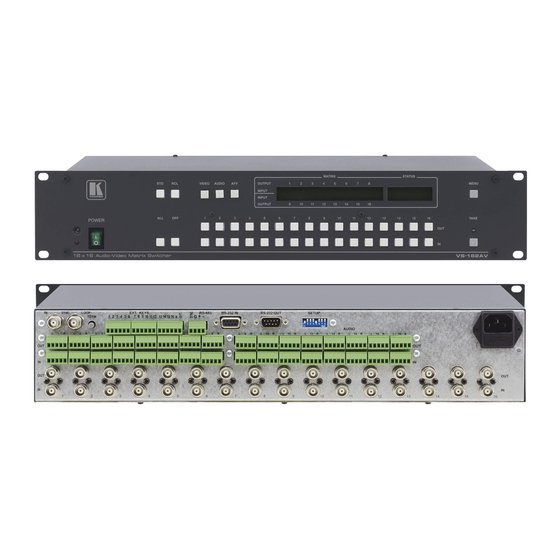
Your Audio-Video Matrix Switcher Figure 2 illustrates the front and rear panels of the VS-162AV. Figure 3 illustrates the front and rear panels of the VS-162AVRCA. Table 2 and Table 3 define the front and rear panels of the unit. -
Page 9: Figure 2: Vs-162Av 16X16 Audio-Video Matrix Switcher
+ - G - + + - G - + + - G - + + - G - + + - G - + + - G - + + - G - + Figure 2: VS-162AV 16x16 Audio-Video Matrix Switcher... -
Page 10: Figure 3: Vs-162Avrca 16X16 Audio-Video Matrix Switcher
Your Audio-Video Matrix Switcher MATRIX STATUS OUTPUT MENU INPUT INPUT OUTPUT TAKE Figure 3: VS-162AVRCA 16x16 Audio-Video Matrix Switcher KRAMER: SIMPLE CREATIVE TECHNOLOGY... -
Page 11: Table 2: Front Panel Unit Features
Your Audio-Video Matrix Switcher Table 2: Front Panel Unit Features Feature Function IR Receiver The red LED is illuminated when receiving signals from the Kramer Infra- red remote control transmitter POWER Switch Illuminated switch supplying power to the unit ALL Button... -
Page 12: Installing The Audio-Video Matrix Switcher
VS-1616V (a 16x16 analog video matrix switcher), the VS-1616A (a 16x16 analog balanced stereo audio matrix switcher), and the VS-162V (a 16x16 video matrix switcher) 3 The VS-162AVRCA (unlike the VS-162AV) is configured for unbalanced stereo audio with 16 inputs and 16 outputs on RCA connectors 4 However, for an unbalanced stereo audio input, the output will always be half of the input signal. -
Page 13: Connecting A Balanced Stereo Audio Input / Output (Vs-162Av)
Installing the Audio-Video Matrix Switcher Figure 4: Configuring the VS-162AV as a Stand Alone Switcher 6.1.1 Connecting a Balanced Stereo Audio Input / Output (VS-162AV) Figure 5 illustrates a balanced stereo audio input # 1: Figure 5: Connecting a Balanced Stereo Audio Input # 1 6.1.2... -
Page 14: Assembling A System Of Interconnected Switchers
MACHINE # 2 and the 16x16 digital audio matrix switcher is MACHINE # 3. Control of the system is via the MACHINE #’s. 16x16 Audio-Video Matrix Switcher VS-162AV / VS-162AVRCA Unit MACHINE # 1 16x16 Digital Video Matrix Switcher... -
Page 15: Dipswitch Settings
Installing the Audio-Video Matrix Switcher Refer to section 6.3 for details of how to set the dipswitches, and to section 6.4 for details of how to control this group of interconnected varied-format 16x16 series switchers, and other configurations. 6.3 Dipswitch Settings Configure the unit by setting the 8 dipswitches as Figure 8 and Table 4 define: SYSTEM MODE SLAVE MODE... -
Page 16: Understanding The System Mode
8.2 for a description of the MENU’s Follow-SYSTEM and Breakaway-from- SYSTEM modes. 1 Video and the audio channels switch simultaneously in the same way 2 Audio channels switch independently from the video channels 3 See section 6.1 4 See section 6.2 KRAMER: SIMPLE CREATIVE TECHNOLOGY... -
Page 17: Understanding The Slave Mode
Installing the Audio-Video Matrix Switcher 6.3.3 Understanding the SLAVE Mode The SLAVE mode is only used for the multi-channel video switcher configuration, for example, when joining together two units. Two units could be configured as a 16x16 s-Video (Y/C) with 4-channel stereo audio. One unit is used as the Master, and the other unit is the Slave. -
Page 18: Connecting The Rs-232 Control Interface
(from the series of 16x16 matrix switchers) according to your requirements, and not according to a fixed sequence dependent on the MACHINE # and/or MACHINE ADDRESS #. Figure 9: Connecting a PC to 4 Units KRAMER: SIMPLE CREATIVE TECHNOLOGY... -
Page 19: Connecting 2 Units Using A Null-Modem Adapter
Installing the Audio-Video Matrix Switcher You can connect any of the following: • 2 units, using a Null-modem adapter (see section 6.4.1.1) or without using a Null-modem adapter (see section 6.4.1.2) • The PC’s DB9 COM port to a unit with a Null-modem adapter (see section 6.4.1.3) or without a Null-modem adapter (see section 6.4.1.4) •... -
Page 20: Pc Db25 Com Port Connection To A Unit
The RS-485 connector is also used (if required) for vertical sync: Figure 11: RS-485 Connector PINOUT 1 Straight one-to-one uncrossed connections with at least the 3 wires pins # 2, # 3 and # 5 KRAMER: SIMPLE CREATIVE TECHNOLOGY... -
Page 21: Figure 12: Connecting The Rs-485 Connectors
Figure 13 illustrates the RS-485 line that connects: • Between the unit, the VS-1616SDI and the VS-1616AD units • To the PC via a Kramer Tools VP-43xl Interface Converter (connect the PC’s DB 9 COM port to the “RS-232 in” DB9F port on the VP-43xl. -
Page 22: Configuring The Sync
Installing the Audio-Video Matrix Switcher MACHINE ADDRESS # 1 VS-162AV / VS-162AVRCA DIP 8 OFF RS-485 MACHINE ADDRESS # 7 DIP 8 OFF VS-1616SDI RS-485 MACHINE ADDRESS # 2 VS-1616AD DIP 8 ON RS-485 Figure 13: An RS-485 Control Interface Setup 6.5 Configuring the Sync... -
Page 23: Connecting The Keyboard Extension
Installing the Audio-Video Matrix Switcher Configure the sync via the SWITCHING METHOD Menu command setting When setting up multiple machines, linking a common sync to all the machines may be necessary to facilitate simultaneous vertical interval switching. Usually, the easiest method is to choose the sync source from the first machine and then connect all the terminal block connectors. -
Page 24: Operating Your Audio-Video Matrix Switcher
• Several inputs to several outputs • One input to all outputs 1 For instructions on using Kramer Windows®-based Control Software, refer to the separate user manual (included on the CD-ROM in .pdf format), Kramer Control Software 2 Previously known as the IR-1 / IR-1-01 3 Version 1.5 is shown in the Status Display as an example;... -
Page 25: Choosing The Audio-Follow-Video Or Breakaway Mode
Operating Your Audio-Video Matrix Switcher 7.2.1 Choosing the Audio-Follow-Video or Breakaway Mode You can switch video/audio signals in one of 2 ways, either: • BREAKAWAY, in which video and audio channels switch independently; or • AUDIO-FOLLOW-VIDEO (AFV) in which all operations relate to both the video and the audio channels 7.2.1.1 Setting the Breakaway Mode... -
Page 26: Confirming Settings
1 For all actions except storing/recalling setups 2 The CONFIRM mode is the default for storing/recalling setups (see section 8.5) 3 Failure to press the TAKE button within about 30 seconds (the Timeout) will abort the action KRAMER: SIMPLE CREATIVE TECHNOLOGY... -
Page 27: Switching
Operating Your Audio-Video Matrix Switcher 7.2.3 Switching You can switch: • One input to one output (see section 7.2.3.1) • Several inputs to several outputs (see section 7.2.3.2) • One input to all outputs (see section 7.2.3.3) 7.2.3.1 Switching one Input to one Output Pressing an OUT-IN combination when your unit operates in the AT ONCE mode implements the switch immediately. -
Page 28: Switching Several Inputs To Several Outputs
1 For example, pressing OUT button 9 shows the blinking digits 01 if input 1 was previously routed to OUT 9 2 Continuously, within the limit of the timeout (approximately 30 seconds) 3 That corresponds with the second OUT button KRAMER: SIMPLE CREATIVE TECHNOLOGY... -
Page 29: Switching One Input To All Outputs
Operating Your Audio-Video Matrix Switcher 5. Continue with this OUT-IN button sequence, pressing the appropriate OUT and IN buttons, as required. You can also combine an OUT-OFF or OFF-OUT combination with this sequence. 6. After completing the sequence, press the TAKE button to confirm the actions. -
Page 30: Clearing
2 For example, pressing OUT button 9 shows the blinking digits 01 if input 1 was previously routed to OUT 9 3 You can press the OFF button first, and then an OUT button (the order is irrelevant) 4 Continuously, within the limit of the timeout (approximately 30 seconds) KRAMER: SIMPLE CREATIVE TECHNOLOGY... -
Page 31: Clearing Several Outputs
Operating Your Audio-Video Matrix Switcher 3. Press the TAKE button to confirm the action. The input is cleared and the TAKE LED lights. The MATRIX Display does not show any Input # in its place. 7.2.4.2 Clearing several Outputs To clear several outputs (in the AT ONCE mode): 1. -
Page 32: Clearing All Outputs
Press TAKE to execute 3. Press the TAKE button to confirm. All the outputs are cleared and the TAKE LED lights. 1 You can press the OFF button first, and then the ALL button (the order is irrelevant) KRAMER: SIMPLE CREATIVE TECHNOLOGY... -
Page 33: Storing And Recalling Setups
Operating Your Audio-Video Matrix Switcher 7.2.5 Storing and Recalling Setups You can store up to 60 settings in the non-volatile memory with the ability to recall each of those settings. Whenever a setup is stored (and in whatever mode), the following information is saved as an integral part of that stored setup: •... -
Page 34: Recalling Setups
1 above. 1 Alternatively, pressing # 10 followed by # 3 will also enter the # 3 2 VIDEO, AUDIO or AFV 3 That is, a setup # for which no setup is actually stored KRAMER: SIMPLE CREATIVE TECHNOLOGY... -
Page 35: Menu Commands Sequence
MENU Commands Sequence MENU Commands Sequence You can press the MENU button up to 11 times in straight sequence to scan the range of commands. LOCK front panel ? yes -> TAKE, next -> MENU Operational Control Change the current state by Follow the SYSTEM pressing the TAKE button yes ->... -
Page 36: Locking And Unlocking The Front Panel
MENU Pressing a front panel button has no effect but remote RS-232 and RS-485 commands function and show on the MATRIX Display. To unlock the VS-162AV: Either: 1. Press the MENU button. The MATRIX Display shows the message:... -
Page 37: Choosing The Follow-System Or Breakaway-From-System Mode
MENU Commands Sequence 1. Press the TAKE button twice. The front panel unlocks and the same messages show as in steps 1 and 2 above. 8.2 Choosing the Follow-System or Breakaway-From-System Mode The terms audio-follow-video and audio breakaway are well known. Sometimes signals other than audio signals need to switch simultaneously and at other times, need to switch independently. - Page 38 3. Press the TAKE button again. The MATRIX Display shows the message: the UNIT is set in mode BREAKAWAY from system 1 Pressing a different button cancels the operation and the switcher will remain in its previous state KRAMER: SIMPLE CREATIVE TECHNOLOGY...
-
Page 39: Choosing The Switching Method Setting
MENU Commands Sequence 8.3 Choosing the SWITCHING METHOD Setting Section 8.3.1 describes the SWITCHING METHOD settings for stand alone units and large matrices. Section 8.3.2 describes how to configure a SWITCHING METHOD. 8.3.1 Understanding the SWITCHING METHOD Settings Setting the unit as a Stand-Alone UNIT provides a choice of 3 SWITCHING METHOD settings: •... -
Page 40: Configuring A Switching Method
Press TAKE to configure from INTERNAL (Input #1) 4. Press the TAKE button. The Displays show the messages: SWITCHING METHOD current: changed From In #1 1 Indicating that the machine is currently set to the external switching method setting KRAMER: SIMPLE CREATIVE TECHNOLOGY... -
Page 41: Choosing The Extended Keyboard Setting
MENU Commands Sequence 8.4 Choosing the extended Keyboard Setting Section 6.6 describes how to connect a remote keyboard. Activate or deactivate it by setting the extended Keyboard setting ON or OFF. To set the extended KEYBOARD mode, do the following: 1. -
Page 42: Choosing What To Indicate
Figure 18: Choosing what to INDICATE To scroll the switcher setup (instead of showing the AUDIO mode), do the following: 1. Press the MENU button until you reach the “What to INDICATE” command. The MATRIX Display shows the message: KRAMER: SIMPLE CREATIVE TECHNOLOGY... -
Page 43: Choosing The Communication Setting
MENU Commands Sequence what to INDICATE yes -> TAKE, next -> MENU 2. Press the TAKE button. The Displays show the messages: Use OUTkey to configure Current: 1: scroll SETUP 2: AUDIO mode AUDIO 3. Press the OUT button 1. The TAKE LED blinks and the Displays show the messages: Scroll switcher setup? Current:... -
Page 44: Setting The Ir Remote Control
8.8 Setting the IR REMOTE Control Set the IR REMOTE control to enable remote control of the 16x16 Audio- Video Matrix Switcher, using the Kramer Infra-Red Remote Control Device Refer to the Infra-Red Remote Control Device user manual , for full details. -
Page 45: Choosing The Auto Store Current Setup
MENU Commands Sequence 8.9 Choosing the AUTO STORE Current SETUP Choose whether or not to save the current setup automatically, that is, whether to save the machine’s status on power down, so that it returns to the same status after cycling power. To save the current setup automatically (when set OFF), do the following: 1. -
Page 46: Choosing The Initial Reset
(reloads the current setup) • Factory default (resets to the pre-installed factory default state Each VS-162AV unit ships in its factory default To reset the machine, do the following: 1. Press the MENU button until you reach the initial RESET command. -
Page 47: Flash Memory Upgrade
7.1. 9.1 Connecting the PC to the RS-232 Port Before installing the latest Kramer firmware version on a unit, connect: • The COM port on your PC to the RS-232 IN port on the unit When simultaneously upgrading the firmware on several units: •... - Page 48 Note: If upgrading the firmware on more than one unit, be sure to perform the above steps, 5 to 9, on each unit before continuing. 1 Upgrading firmware resets your unit to the factory default. This includes erasing all setups KRAMER: SIMPLE CREATIVE TECHNOLOGY...
- Page 49 If not, repeat the firmware upgrade process from the beginning. 15. You have successfully replaced the previous program and upgraded to the latest Kramer firmware version. Turn the POWER switch on the unit off. Reconnect the RS-232 IN and RS-232 OUT rear panel port connections (as applicable).
-
Page 50: Technical Specifications
VIDEO: 16 composite video 1 Vpp / 75Ω on BNC connectors AUDIO: 16 balanced audio 10kΩ on detachable terminal block connectors (VS-162AV) / 16 unbalanced audio on RCA connectors (VS-162AVRCA) OUTPUTS: VIDEO: 16 composite video 1 Vpp / 75Ω on BNC connectors AUDIO: 16 balanced audio 50Ω... -
Page 51: Table 9: Hex Table For The Vs-162Av / Vs-162Avrca Audio-Video Matrix Switcher
Communication Protocol Table 9: Hex Table for the VS-162AV / VS-162AVRCA Audio-Video Matrix Switcher... - Page 53 For the latest information on our products and a list of Kramer distributors, visit our Web site: www.kramerelectronics.com, where updates to this user manual may be found. We welcome your questions, comments and feedback. Safety Warning: Disconnect the unit from the power supply before opening/servicing.
Need help?
Do you have a question about the VS-162AV and is the answer not in the manual?
Questions and answers