
Related Manuals for Kramer VS-1616A


Summary of Contents for Kramer VS-1616A
- Page 1 Kramer Electronics, Ltd. USER MANUAL Model: VS-1616A 16x16 Balanced Stereo Audio Matrix Switcher...
-
Page 2: Table Of Contents
Contents Introduction Getting Started Overview Your Balanced Stereo Audio Matrix Switcher Installing the VS-1616A in a Rack Installing the Balanced Stereo Audio Matrix Switcher Connecting the Balanced/Unbalanced Stereo Audio Input/Output Operating a Single Machine Assembling a Multi-channel Audio Switcher Assembling an Expanded Matrix Switcher 6.4.1... - Page 3 Identifying the MACHINE 8.12 Choosing the Initial RESET Upgrading the Flash Memory Connecting the PC to the RS-232 Port Upgrading the Firmware Technical Specifications Communication Protocol ASCII Protocol 12.1 Entering the ASCII Protocol 12.2 ASCII Command Description KRAMER: SIMPLE CREATIVE TECHNOLOGY...
- Page 4 Figure 4: Connecting an Unbalanced Stereo Audio Output Figure 5: DIP-Switch Setup on a Single Machine Figure 6: Configuring a 4 Channel 16x16 Switcher with Two VS-1616A Switchers Figure 7: MACHINE ADDRESS # Designation Figure 8: The Principle of Assembling an Expanded Matrix Switcher...
-
Page 5: Introduction
GROUP 4: Format/Standards Converters; GROUP 5: Range Extenders and Repeaters; GROUP 6: Specialty AV Products; GROUP 7: Scan Converters and Scalers; GROUP 8: Cables and Connectors; GROUP 9: Room Connectivity; GROUP 10: Accessories and Rack Adapters; GROUP 11: Sierra Products 2 Download up-to-date Kramer user manuals from our Web site at http://www.kramerelectronics.com... -
Page 6: Overview
The Kramer VS-1616A is a high-performance 16x16 Balanced Stereo Audio Matrix Switcher for balanced audio stereo signals on detachable terminal block connectors. The VS-1616A forms part of the series of 16x16 matrix switchers that includes the VS-162V (a 16x16 video matrix switcher). In particular, the VS-1616A features: •... -
Page 7: Your Balanced Stereo Audio Matrix Switcher
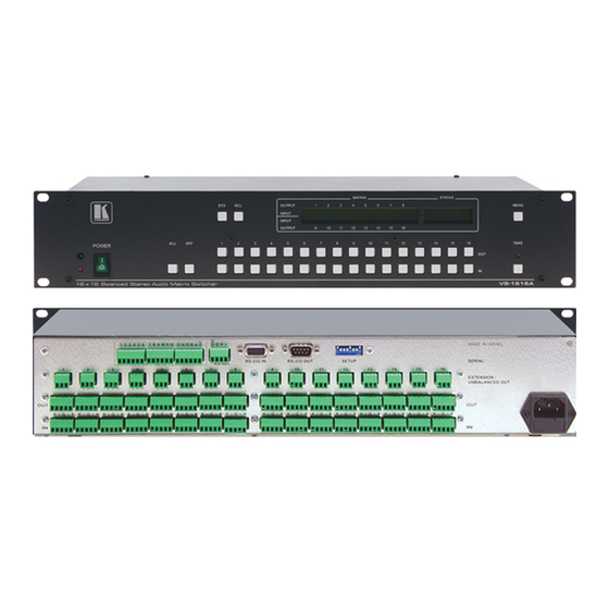
VS-1616A away from moisture, excessive sunlight and dust. Your Balanced Stereo Audio Matrix Switcher Figure 1 illustrates the front and rear panels of the VS-1616A. Table 1 Table 2 define the front and rear panels of the VS-1616A, respectively. -
Page 8: Figure 1: Vs-1616A 16X16 Balanced Stereo Audio Matrix Switcher
Your Balanced Stereo Audio Matrix Switcher Figure 1: VS-1616A 16x16 Balanced Stereo Audio Matrix Switcher KRAMER: SIMPLE CREATIVE TECHNOLOGY... -
Page 9: Table 1: Front Panel Vs-1616A Features
2 If the unit is not the first unit in the line, connects to the RS-232 OUT 9-pin D-sub (F) port of the previous unit in the line 3 Optional. Can be used instead of the front panel (built-in) IR receiver to remotely control the VS-1616A (only if the internal... -
Page 10: Installing The Vs-1616A In A Rack
Installing the VS-1616A in a Rack Installing the VS-1616A in a Rack This section describes how to install the VS-1616A in a rack. Before Installing in a rack How to Rack Mount Before installing in a rack, be sure that the environment is... -
Page 11: Installing The Balanced Stereo Audio Matrix Switcher
Figure 3: Connecting the Figure 4: Connecting an Balanced Stereo Audio Unbalanced Stereo Unbalanced Stereo Input/Output Audio Input Audio Output 1 Switch OFF the power on each device before connecting it to your VS-1616A 2 Including the VS-162V (a 16x16 video matrix switcher) -
Page 12: Operating A Single Machine
Installing the Balanced Stereo Audio Matrix Switcher Operating a Single Machine By default, the VS-1616A is setup for use as a single machine. This means that it is a 16x16 balanced stereo audio matrix switcher. In particular, be sure that the DIP-switches are set as... -
Page 13: Assembling An Expanded Matrix Switcher
French) or to produce surround sound (in which the sound is supplied to 4 speakers arranged in each corner of a room). Figure 6: Configuring a 4 Channel 16x16 Switcher with Two VS-1616A Switchers Assembling an Expanded Matrix Switcher... -
Page 14: Assembling A 32X16 Switcher
Figure 8: The Principle of Assembling an Expanded Matrix Switcher 6.4.1 Assembling a 32x16 Switcher As can be seen in Figure 7, a 32x16 switcher consists of 2 VS-1616A units (MACHINE ADDRESS # 1 and MACHINE ADDRESS # 7). To assemble, as Figure 9 illustrates:... - Page 15 Set DIP 6 OFF on both VS-1616A units. Interconnect each corresponding EXTENSION / UNBALANCED OUT connector between both VS-1616A units (1 to 1, 2 to 2, 3 to 3, up to and including 16 to 16). Connect the balanced outputs 1 to 16 from the first VS-1616A unit...
-
Page 16: Assembling A 32X32 Switcher
Set the MACHINE ADDRESS # to 1, 2, 7 and 8 on each of the 4 units, respectively (refer to Figure Set DIP 6 OFF on each of the 4 VS-1616A units. Interconnect the corresponding EXTENSION / UNBALANCED OUT connectors between the same EXTENSION / UNBALANCED OUT connectors, as follows: •... - Page 17 MACHINE ADDRESS # 8 and MACHINE ADDRESS Connect INPUTS 1 to 16 on the VS-1616A unit designated as MACHINE ADDRESS # 2 with INPUTS 1 to 16 on the VS-1616A unit designated as MACHINE ADDRESS # 1. INPUTS 1 to 16 become the SYSTEM INPUTS 1 to 16.
-
Page 18: Assembling A System Of Interconnected Switchers
Figure 10: Connecting the 32x32 Switcher Assembling a System of Interconnected Switchers A major advantage of the VS-1616A is that it belongs to the series of 16x16 matrix switchers and, as such, can interconnect with other switchers in the series. -
Page 19: Figure 11: Assembling A System Of Interconnected Switchers
Installing the Balanced Stereo Audio Matrix Switcher Note that each group of switchers has a unique MACHINE # that is shared by all members of the group. In Figure 11, the 32x32 composite video matrix switcher is MACHINE # 1, the 32x16 digital video matrix switcher is MACHINE # 2 and so on. -
Page 20: Setting The Dip-Switches
16x16 series switchers, and other configurations. Setting the DIP-switches Configure the VS-1616A by setting the 8 DIP-switches as Figure 12 Table 4 define: Figure 12: Rear Panel DIP-switches... -
Page 21: Setting The Machine Address
A valid MACHINE ADDRESS # is from 1 to 36. 6.6.3 Understanding the SYSTEM Mode DIP 5 defines whether the VS-1616A unit communicates with other switchers via a common control line. You can set DIP 5 OFF to disable the Follow-SYSTEM mode in the following applications: •... -
Page 22: Understanding The Slave Mode
6, the first VS-1616A unit is the Master (with DIP 6 set OFF disabling the Slave mode) and the second VS-1616A unit is a Slave (with DIP 6 set ON enabling the Slave mode). On the Slave VS-1616A unit, the MATRIX and STATUS Displays do... -
Page 23: Connecting The Rs-232 Control Interface
(from the series of 16x16 matrix switchers) according to your requirements, and not according to a fixed sequence dependent on the MACHINE # and/or MACHINE ADDRESS #. Figure 13: Connecting a PC to 4 VS-1616A Units... -
Page 24: Connecting Two Vs-1616As With A Null-Modem Adapter
6.7.1.3 Connecting to a 9-pin D-sub COM Port with a Null-modem Adapter To connect the PC’s 9-pin D-sub COM port to a VS-1616A unit, using a null-modem adapter: Connect a flat cable between the PC’s 9-pin D-sub COM port and the Null-modem adapter that attaches to the RS-232 IN 9-pin D-sub port on the VS-1616A unit. -
Page 25: Connecting To A 9-Pin D-Sub Com Port Without A Null-Modem Adapter
6.7.1.5 Connecting to a 25-pin D-sub COM Port with a Null-modem Adapter To connect the PC’s 25-pin D-sub COM port to a VS-1616A unit, using a null-modem adapter: Connect a flat cable between the PC’s 25-pin D-sub COM port and the Null-modem adapter that attaches to the RS-232 IN 9-pin D-sub port on the first VS-1616A unit. -
Page 26: Connecting The Rs-485 Control Interface
(from the series of 16x16 matrix switchers), as Figure 16 illustrates: Connect the “+” PIN on the first VS-1616A unit to the “+” PIN on the second VS-1616A unit or other unit 1 See section KRAMER: SIMPLE CREATIVE TECHNOLOGY... -
Page 27: Figure 16: Connecting The Rs-485 Connectors Between 2 Vs-1616A Units
Installing the Balanced Stereo Audio Matrix Switcher Connect the “-” PIN on the first VS-1616A unit to the “-” PIN on the second VS-1616A unit or other unit If shielded cable is used for an RS-485 connection, connect the shield to the Ground PIN. -
Page 28: Figure 17: An Rs-485 Control Interface Setup
Installing the Balanced Stereo Audio Matrix Switcher Figure 17: An RS-485 Control Interface Setup KRAMER: SIMPLE CREATIVE TECHNOLOGY... -
Page 29: Configuring The Sync
MTX (Sync from Matrix) RS-485 Terminal Block connector. For example, a video-audio switcher (using VS-162V and VS-1616A), linking a common sync to all the machines may be necessary to facilitate simultaneous vertical interval switching. Usually, the easiest method is to choose the sync source from any video... -
Page 30: Operating Your Balanced Stereo Audio Matrix Switcher
1 For instructions on using Kramer Windows®-based control software, refer to the separate user manual (included on the CD- ROM in .pdf format), Kramer Control Software 2 Version 1.5 is shown in the Status Display as an example; text in the Matrix Display may vary (according to machine... -
Page 31: Using The Front Panel Buttons
Operating Your Balanced Stereo Audio Matrix Switcher Figure 19: Default Startup Status Display Sequence Using the Front Panel Buttons You can switch (see section 7.2.2) and clear (see section 7.2.3): • One input to one output • Several inputs to several outputs •... -
Page 32: Toggling Between The At Once And Confirm Modes
One input to all outputs (see section 7.2.2.3) 7.2.2.1 Switching One Input to One Output Pressing an OUT-IN combination when your VS-1616A operates in the AT ONCE mode implements the switch immediately. To switch one input to one output (AT ONCE mode): Press the appropriate OUT button. -
Page 33: Switching Several Inputs To Several Outputs
# y Where x is the output number and y is the input number Pressing an OUT-IN combination when your VS-1616A operates in the CONFIRM mode (and the TAKE LED is lit), requires user confirmation. To switch one input to one output (CONFIRM mode): Repeat step 1 above. -
Page 34: Switching One Input To All Outputs
Press the TAKE button to confirm the action. The selected input switches to all the outputs and the TAKE LED lights. 1 Continuously, within the limit of the timeout (approximately 30 seconds to one minute) 2 That corresponds with the second OUT button KRAMER: SIMPLE CREATIVE TECHNOLOGY... -
Page 35: Clearing Outputs
Operating Your Balanced Stereo Audio Matrix Switcher The MATRIX Display shows the identical 2 non-blinking digits (representing that input number) for all outputs. 7.2.3 Clearing Outputs You can clear (delete): • One output (see section 7.2.3.1) • Several outputs (see section 7.2.3.2) •... -
Page 36: Clearing Several Outputs
Continue with this OUT-OFF button sequence, pressing the appropriate OUT buttons and the OFF, as required. 1 For example, pressing OUT button 9 shows the blinking digits 01 if input 1 was previously routed to OUT 9 KRAMER: SIMPLE CREATIVE TECHNOLOGY... -
Page 37: Clearing All Outputs
Operating Your Balanced Stereo Audio Matrix Switcher The MATRIX Display shows the sets of 2 blinking digits, representing the present input number for each specific output. After completing the sequence, press the TAKE button to confirm the actions. The inputs are cleared and the TAKE LED lights. The MATRIX Display does not show any Input # in its place. -
Page 38: Storing Setups
The Displays show the messages: Enter SETUP number RECALL use two digit # 01-99 # xy Where xy are the OUT buttons. 1 However, pressing # 3 followed by the TAKE button will also enter the # 3 KRAMER: SIMPLE CREATIVE TECHNOLOGY... -
Page 39: Viewing The Menu Commands Sequence
Viewing the MENU Commands Sequence Press the appropriate two OUT buttons, using the OUTkeys # 1 to 9, and 10 (for 0). The OUTkeys function on a decimal-basis, and not on a positional-basis. For example, to enter the # 14, press # 1 followed by # 4 (not # 14). -
Page 40: Figure 20: Sequence Of Menu Commands
MACHINE yes -> TAKE, next -> MENU initial RESET yes -> TAKE, next -> MENU Figure 20: Sequence of MENU Commands You can stop changing a setup at any time by pressing any IN button. KRAMER: SIMPLE CREATIVE TECHNOLOGY... -
Page 41: Locking And Unlocking The Front Panel
Viewing the MENU Commands Sequence Locking and Unlocking the Front Panel To prevent changing the settings accidentally or tampering with the unit via the front panel buttons, lock your VS-1616A. Unlocking releases the protection mechanism. To lock the VS-1616A: Press the MENU button once. -
Page 42: Choosing The Follow-System Or Breakaway-From-System Mode
3 16x16 matrix switchers in the same series, that include, for example, the VS-162V (16x16 video matrix switcher) units 4 Also applies to a VS-162V unit 5 The VS-1616A unit changes its status immediately and goes to the Follow-system mode 6 Or VS-162V (as well as other 16x16 matrix switchers in the same series) - Page 43 UNIT is set in mode FOLLOW system If the status of the VS-1616A unit differs from that of the other unit(s), set the VS-1616A unit to the Follow-SYSTEM mode. The MATRIX Display blinks the new status of the switcher and the TAKE LED blinks. Pressing...
-
Page 44: Setting The Machine Address
The TAKE LED blinks and the Displays show the messages: Change to the LARGE MATRIX? Current 16x16 Press TAKE to confirm 1 Indicating that the machine is not set to the large matrix setting 2 For example, if currently configured for stand alone KRAMER: SIMPLE CREATIVE TECHNOLOGY... - Page 45 Viewing the MENU Commands Sequence Press the TAKE button again. The Displays show the messages: READY to set MACHINE ADDRESS Current # use OUTkey 1-9, 0 Enter the MACHINE ADDRESS by pressing an OUT button # 1-9, 0. The STATUS Display shows the message: current: Where x is the OUT button # pressed Press the TAKE button again.
-
Page 46: Changing The Machine Address From A Large Matrix To Standalone
Press the MENU button until you reach the MACHINE ADDRESS command. The MATRIX Display shows the message: MACHINE ADDRESS setting yes -> TAKE, next -> MENU 1 Indicating that the machine is not set to stand alone KRAMER: SIMPLE CREATIVE TECHNOLOGY... - Page 47 Viewing the MENU Commands Sequence Press the TAKE button. The Displays show the messages: OUTkey 1: Stand-Alone UNIT Current 2: Large Matrix Matrix Press the OUT button # 2. The Displays show the messages: set NEW matrix current: new -> TAKE leave old -> MENU 16x32 Press the TAKE button again.
-
Page 48: Choosing The Switching Method Setting
RS-232 or RS-485 command, or an IR command. The switching is independent of the video vertical reference. Setting the VS-1616A unit as one unit in a system of interconnected switchers (instead of as a Stand-Alone UNIT) provides a choice of 2 SWITCHING METHOD settings: •... -
Page 49: Configuring A Switching Method
Viewing the MENU Commands Sequence (SYNC from Matrix) setting Figure 21: Choosing the MTX (SYNC from Matrix) Setting 8.4.2 Configuring a SWITCHING METHOD To choose a SWITCHING METHOD setting, do the following: Press the MENU button until you reach the SWITCHING METHOD setting. -
Page 50: Choosing The Extended Keyboard Setting
Press the MENU button until reaching the STORE/RECALL setting. The MATRIX Display shows the message: 1 Indicating that the external keys are currently activated 2 The AT ONCE mode is the default for all actions except storing/recalling setups KRAMER: SIMPLE CREATIVE TECHNOLOGY... -
Page 51: Choosing What To Indicate
Viewing the MENU Commands Sequence STORE/RECALL setting yes -> TAKE, next -> MENU Press the TAKE button and choose the appropriate Outkey 1 for the AT ONCE mode (Outkey 2 is for the CONFIRM mode). The Displays show the messages: STO/RCL mode current: changed... -
Page 52: Choosing The Communication Setting
The Displays show the messages: SWITCHER RESPONSE Current: changed No reply Setting the IR REMOTE Control Set the IR REMOTE control to enable remote control of the VS-1616A 16x16 Balanced Stereo Audio Matrix Switcher, using the Kramer RC-IR2 KRAMER: SIMPLE CREATIVE TECHNOLOGY... -
Page 53: Table 6: Summary Of Basic Rc-Ir2 Setups
SHIFT + STO/RCL + # key (for the setup) 1 After enabling the IR REMOTE control command, remotely control the VS-1616A via the RC-IR2 remote control transmitter pointed at the remote receiver on the front panel of the VS-1616A (item 1 in Figure 2 You can download it from the Internet www.kramerelectronics.com... -
Page 54: Choosing The Auto Store Current Setup
Press the MENU button until you reach the Identifying the MACHINE command. The MATRIX Display shows the message: identify MACHINE yes -> TAKE, next -> MENU Press the TAKE button. The MATRIX Display (as Figure 23 illustrates) shows the message: KRAMER: SIMPLE CREATIVE TECHNOLOGY... -
Page 55: Choosing The Initial Reset
1 Without having to switch the power off and on 2 Sometimes called a “soft reset” 3 Each VS-1616A unit ships in its factory default state that is a 16x16 balanced stereo audio matrix, with all setups empty and each input connected to its corresponding output (for example, 1-to-1) -
Page 56: Upgrading The Flash Memory
Connect the COM port on your PC to the RS-232 IN port on the first VS-1616A unit • Connect the RS-232 OUT port on the first VS-1616A unit to the RS-232 IN port on the second VS-1616A unit or another 16x16 unit •... - Page 57 10. After a few seconds the FLASH memory is erased and the MATRIX Display shows the following message: Ready for receiving Start transmission from PC 1 Upgrading firmware resets your VS-1616A unit to the factory default. This includes erasing all setups...
- Page 58 Upgrading the Flash Memory Note: If upgrading the firmware on more than one VS-1616A unit, be sure to perform the above steps, 5 to 9, on each VS-1616A unit before continuing. 11. From your PC’s K-Sender program, click the Send button.
-
Page 59: Technical Specifications
Technical Specifications Technical Specifications Table 8 includes the technical specifications: Table 8: Technical Specifications of the VS-1616A Video Matrix Switcher 16 balanced audio stereo, +4dBu/10kΩ on detachable terminal blocks INPUT: 16 balanced audio stereo, +4dBu/50Ω on detachable terminal blocks OUTPUTS: MAX. -
Page 60: Table 9: Hex Table For The Vs-1616A Video Matrix Switcher
Communication Protocol Table 9: Hex Table for the VS-1616A Video Matrix Switcher KRAMER: SIMPLE CREATIVE TECHNOLOGY... -
Page 61: Ascii Protocol
This is saved in the non-volatile memory, so the machine remains in ASCII even after turning OFF and ON. To check that the protocol has been selected, and to confirm that the communication is OK, send the string **!! to the VS-1616A. It should reply by sending the string OK!! 12.2 ASCII Command Description The three basic commands are Y, T, and P. - Page 62 ** P s# !! where s# is the setup number (up to 99) that stores the present status of the machine. Example: **P13!! stores in setup number 13 The reply for all commands is: OK!! or ERROR!! KRAMER: SIMPLE CREATIVE TECHNOLOGY...
- Page 63 EXCLUSION OF DAMAGES The liability of Kramer for any effective products is limited to the repair or replacement of the product at our option. Kramer shall not be liable for: 1. Damage to other property caused by defects in this product, damages based upon inconvenience, loss of use of the product, loss of time, commercial loss;...
- Page 64 For the latest information on our products and a list of Kramer distributors, visit our Web site: www.kramerelectronics.com where updates to this user manual may be found. We welcome your questions, comments and feedback. Safety Warning: Disconnect the unit from the power supply before opening/servicing.
Need help?
Do you have a question about the VS-1616A and is the answer not in the manual?
Questions and answers