Table of Contents
Advertisement
Quick Links
Advertisement
Table of Contents

Related Manuals for Kramer VS-1616V


Summary of Contents for Kramer VS-1616V
- Page 1 Kramer Electronics, Ltd. USER MANUAL Model: VS-1616V 16x16 Video Matrix Switcher...
-
Page 2: Table Of Contents
6.6.1.3 PC DB9 COM Port Connection to a VS-1616V Unit with a Null-modem Adapter 6.6.1.4 PC DB9 COM Port Connection to a VS-1616V Unit with no Null-modem Adapter 22 6.6.1.5 PC DB25 COM Port Connection to a VS-1616V Unit with a Null-modem Adapter 22 6.6.1.6 PC DB25 COM Port Connection to a VS-1616V Unit with no Null-modem Adapter 22... - Page 3 Setting the IR REMOTE Control 8.11 Choosing the AUTO STORE Current SETUP 8.12 Identifying the MACHINE 8.13 Choosing the initial RESET Flash Memory Upgrade Connecting the PC to the RS-232 Port Upgrading Firmware Technical Specifications Communication Protocol KRAMER ELECTRONICS, LTD.
- Page 4 Table 3: Rear Panel VS-1616V 16x16 Video Matrix Switcher Features Table 4: Stand Alone Switcher Configuration for CV, Y/C, YUV (RGB) and RGBS Table 5: Multi-channel VS-1616V Configuration for CV, Y/C, YUV (RGB) and RGBS 10 Table 6: Dipswitch Definitions...
- Page 5 ADDENDUM: VS-1616A, VS-1616AD, VS-1616SDI, VS-1616V, and VS-162V This addendum describes the ASCII protocol in the 1616 series. The ASCII protocol applies to firmware version 3.3 or higher. ASCII Protocol: General The ASCII protocol has 3 basic commands: Y for connect, T for recall, P for store.
-
Page 6: Introduction
Kramer line an integral part of the finest production and presentation facilities in the world. In recent years, Kramer has redesigned and upgraded most of the line, making the best even better! The Kramer line of professional video/audio... -
Page 7: Overview
5x5 for YUV or RGB (with the sync on the Green signal - RG s B) 4x4 for RGBS signals A main advantage of the VS-1616V is that it forms part of the series of 16x16 matrix switchers that includes, but is not limited to, VS-1616A (a 16x16... -
Page 8: Summary Of How To Operate A Single Machine
Summary of how to Operate a Single Machine By default, the VS-1616V is setup for use as a single machine. This means that it is: A 16x16 composite video switcher... -
Page 9: Your Video Matrix Switcher
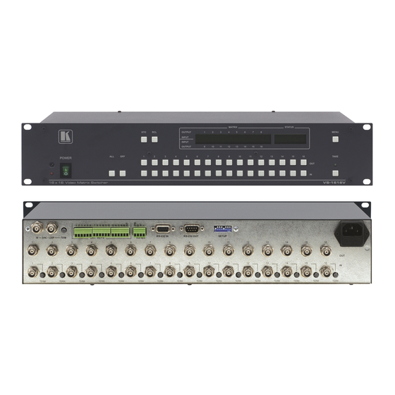
Menu setup command and follow the instructions Your Video Matrix Switcher Figure 2 illustrates the front and rear panels of the VS-1616V. Tables 1 and 2 define the front and rear panels of the VS-1616V, respectively. KRAMER ELECTRONICS, LTD. -
Page 11: Table 2: Front Panel Vs-1616V 16X16 Video Matrix Switcher Features
Table 2: Front Panel VS-1616V 16x16 Video Matrix Switcher Features Feature Function IR Receiver The red LED is illuminated when receiving signals from the Kramer Infra-red remote control transmitter Power Switch Illuminated switch supplying power to the unit ALL Button... -
Page 12: Installing The Video Matrix Switcher
YUV / RGB RGBS 1 Switch OFF the power on each device before connecting it to your VS-1616V 2 Including the VS-1616A (a 16x16 analog balanced stereo audio matrix switcher), the VS-1616VD (a 16x16 digital video matrix switcher), the VS-1616AD (a 16x16 digital audio matrix switcher), and the VS-1616RS (an RS-422 control signal... -
Page 13: Configuring A Single Vs-1616V Unit (16X16 Cv) For Composite Video
6.1.1 Configuring a single VS-1616V Unit (16x16 CV) for Composite Video By default, a single VS-1616V unit is configured for composite video with 16 inputs and 16 outputs, as Figure 3 illustrates: Figure 3: Configuring the VS-1616V for Composite Video (CV) 6.1.2... -
Page 14: Configuring A Single Vs-1616V Unit (4X4) Rgbs Switcher
Configure VS-1616V units as a 16x16 multi-channel video switcher for: s-Video (Y/C) (see section 6.2.1) YUV (RGB) (see section 6.2.2) RGBS (see section 6.2.3) Use several VS-1616V units to expand the system, as Table 5 defines. For example, for composite configuration a single VS-1616V unit provides 16... -
Page 15: Configuring A 16X16 Y/C Switcher (2 Units)
VS-1616V switchers, as Figure 7 illustrates: 1 The front panel is not locked and the MATRIX and STATUS LCD Displays illuminate 2 For a description of how to connect the RS-485 connectors between the VS-1616V switchers, refer to section 6.6.2 KRAMER ELECTRONICS, LTD. -
Page 16: Configuring A 16X16 Rgbs Switcher (4 Units)
Installing the Video Matrix Switcher Figure 7: Configuring a 16x16 YUV (RGB) Switcher with 3 VS-1616V Switchers 6.2.3 Configuring a 16x16 RGBS Switcher (4 Units) Configure 4 VS-1616V switchers as a 16x16 video matrix switcher for RGBS, in a similar way to how Figure 7 in section 6.2.2 illustrates combining... -
Page 17: Assembling An Expanded Matrix Switcher
Figure 8: MACHINE ADDRESS # Designation 6.3.1 Assembling a 32x16 Switcher As can be seen in Figure 8, a 32x16 switcher consists of 2 VS-1616V units (MACHINE ADDRESS # 1 and MACHINE ADDRESS # 7). To assemble, as Figure 9 illustrates: 1. -
Page 18: Assembling A 32X32 Switcher
Installing the Video Matrix Switcher 2. Set the MACHINE ADDRESS # on one VS-1616V unit to 1 and on the other VS-1616V unit to 7 (refer to Figure 8). 3. Set DIP 6 OFF on both VS-1616V units. 4. Using T-connectors, connect OUTPUTS 1 to 16 on both VS-1616V units. - Page 19 Installing the Video Matrix Switcher 3. Set DIP 6 OFF on each of the 4 VS-1616V units. 4. Using T-connectors, connect INPUTS 1 to 16 on the VS-1616V unit designated as MACHINE ADDRESS # 2 with INPUTS 1 to 16 on the VS-1616V unit designated as MACHINE ADDRESS # 1.
-
Page 20: Assembling A System Of Interconnected Switchers
Figure 10: Connecting the 32x32 Switcher 6.4 Assembling a System of Interconnected Switchers A major advantage of the VS-1616V is that it belongs to the series of 16x16 matrix switchers and, as such, can interconnect with other switchers in the series. -
Page 21: Figure 11: Assembling A System Of Interconnected Switchers
Figure 11: Assembling a System of Interconnected Switchers Refer to section 6.5 for details of how to set the dipswitches, and to section 6.6 for details of how to control this group of interconnected varied-format 16x16 series switchers, and other configurations. KRAMER ELECTRONICS, LTD. -
Page 22: Dipswitch Settings
Installing the Video Matrix Switcher 6.5 Dipswitch Settings Configure the VS-1616V by setting the 8 dipswitches as Figure 12 and Table 6 define: Figure 12: Rear Panel Dipswitches Table 6: Dipswitch Definitions Dipswitch # Function: Set the MACHINE # (see Table 7 in section 6.5.1) -
Page 23: Setting The Machine Address
A valid MACHINE ADDRESS # is from 1 to 36. 6.5.3 Understanding the SYSTEM Mode DIP 5 defines whether the VS-1616V unit communicates with other switchers via a common control line. You can set DIP 5 OFF to disable the Follow-SYSTEM mode in the... -
Page 24: Understanding The Slave Mode
Master. In the example illustrated in Figure 7, the first VS-1616V unit is the Master (with DIP 6 set OFF disabling the Slave mode) and the second and third VS-1616V units are Slaves (with DIP 6 set ON enabling the Slave mode). -
Page 25: Connecting The Rs-232 Control Interface
(from the series of 16x16 matrix switchers) according to your requirements, and not according to a fixed sequence dependent on the MACHINE # and/or MACHINE ADDRESS #. Figure 13: Connecting a PC to 4 VS-1616V Units KRAMER ELECTRONICS, LTD. -
Page 26: Connecting 2 Vs-1616V Units Using A Null-Modem Adapter
6.6.1.3 PC DB9 COM Port Connection to a VS-1616V Unit with a Null-modem Adapter To connect the PC’s DB9 COM port to a VS-1616V unit, using a Null- modem adapter: 1. Connect a flat cable between the PC’s DB9 COM port and the Null- modem adapter that attaches to the RS-232 IN DB9 port on the VS-1616V unit. -
Page 27: Pc Db9 Com Port Connection To A Vs-1616V Unit With No Null-Modem Adapter
Installing the Video Matrix Switcher 6.6.1.4 PC DB9 COM Port Connection to a VS-1616V Unit with no Null-modem Adapter To connect the PC’s DB9 COM port to a VS-1616V unit, without using a Null-modem adapter: 1. Connect a flat cable between the PC’s DB9 COM port and the RS-232... -
Page 28: Connecting The Rs-485 Control Interface
(from the series of 16x16 matrix switchers), as Figure 16 illustrates: 1. Connect the “+” PIN on the first VS-1616V unit to the “+” PIN on the second VS-1616V unit or other unit 2. -
Page 29: Figure 16: Connecting The Rs-485 Connectors Between 2 Vs-1616V Units
To the PC via a Kramer Tools VP-43xl Interface Converter (connect the PC’s DB 9 COM port to the “RS-232 in” DB9F port on the VP-43xl. Next, connect the RS-485 port on the VP-43xl to the RS-485 ports on the VS-1616V units) -
Page 30: Figure 17: An Rs-485 Control Interface Setup
Installing the Video Matrix Switcher Figure 17: An RS-485 Control Interface Setup... -
Page 31: Configuring The Sync
Installing the Video Matrix Switcher 6.7 Configuring the Sync On the VS-1616V, you can select one of the following, as the sync input: EXTERNAL (“sync in” BNC connector) INPUT # 1 BNC connector MTX (Sync from Matrix) RS-485 Terminal Block connector, when using... -
Page 32: Operating Your Video Matrix Switcher
After switching on the power, the MATRIX and STATUS displays show the following screens in sequence: 1 For instructions on using Kramer Windows 95/98/NT Control Software, refer to the separate user manual (included on the CD-ROM in .pdf format), Kramer Control Software 2 Version 1.5 is shown in the Status Display as an example;... -
Page 33: Using The Front Panel Buttons
1 For all actions except storing/recalling setups 2 The CONFIRM mode is the default for storing/recalling setups (see section 8.7) 3 Failure to press the TAKE button within 30 seconds to one minute (the Timeout) will abort the action KRAMER ELECTRONICS, LTD. -
Page 34: Toggling Between The At Once And Confirm Modes
One input to all outputs (see section 7.2.2.3) 7.2.2.1 Switching one Input to one Output Pressing an OUT-IN combination when your VS-1616V operates in the AT ONCE mode implements the switch immediately. To switch one input to one output (AT ONCE mode): 1. -
Page 35: Switching Several Inputs To Several Outputs
# y Where x is the output number and y is the input number Pressing an OUT-IN combination when your VS-1616V operates in the CONFIRM mode (and the TAKE LED is lit), requires user confirmation. To switch one input to one output (CONFIRM mode): 1. -
Page 36: Switching One Input To All Outputs
Operating Your Video Matrix Switcher 2. Press the appropriate IN button. The MATRIX Display shows the 2 blinking digits, representing the input number and the TAKE LED blinks. The STATUS Display shows the message: out # x from in # y Where x is the output number and y is the input number 3. -
Page 37: Clearing
2 For example, pressing OUT button 9 shows the blinking digits 01 if input 1 was previously routed to OUT 9 3 You can press the OFF button first, and then an OUT button (the order is irrelevant) KRAMER ELECTRONICS, LTD. -
Page 38: Clearing Several Outputs
Operating Your Video Matrix Switcher previous 2 blinking digits and the TAKE LED blinks. The STATUS Display shows the message: out # x reset Where x is the output number 3. Press the TAKE button to confirm the action. The input is cleared and the TAKE LED lights. The MATRIX Display does not show any Input # in its place. -
Page 39: Clearing All Outputs
Press TAKE to execute 3. Press the TAKE button to confirm. All the outputs are cleared and the TAKE LED lights. 1 You can press the OFF button first, and then the ALL button (the order is irrelevant) KRAMER ELECTRONICS, LTD. -
Page 40: Storing And Recalling Setups
Operating Your Video Matrix Switcher 7.2.4 Storing and Recalling Setups You can store up to 99 settings in the non-volatile memory with the ability to recall each of those settings. 7.2.4.1 Storing Setups To store a setting, do the following: 1. -
Page 41: Menu Commands Sequence
You can press the MENU button up to 13 times in straight sequence to scan the range of commands. 1 However, pressing # 3 followed by the TAKE button will also enter the # 3 2 That is, a setup # for which no setup is actually stored KRAMER ELECTRONICS, LTD. -
Page 42: Figure 20: Sequence Of Menu Commands
MENU Commands Sequence LOCK front panel ? yes -> TAKE, next -> MENU Operational Control Change the current state by Follow the SYSTEM pressing the TAKE button yes -> TAKE, next -> MENU VIDEO FORMAT setting yes -> TAKE, next -> MENU MACHINE ADDRESS setting yes ->... -
Page 43: Locking And Unlocking The Front Panel
MENU Commands Sequence 8.1 Locking and Unlocking the Front Panel To prevent changing the settings accidentally or tampering with the unit via your VS-1616V. Unlocking releases the the front panel buttons, lock protection mechanism. To lock the VS-1616V: 1. Press the MENU button once. -
Page 44: Choosing The Follow-System Or Breakaway-From-System Mode
4 Also applies to a VS-1616A unit or a VS-1616AD unit 5 The VS-1616V unit changes its status immediately and goes to the Follow-system mode 6 Or VS-1616A or VS-1616AD unit (as well as other 16x16 matrix switchers in the same series) -
Page 45: Choosing The Video Format Setting
UNIT is set in mode FOLLOW system If the status of the VS-1616V unit differs from that of the other unit(s), set the VS-1616V unit to the Follow-SYSTEM mode. The MATRIX Display blinks the new status of the switcher and the TAKE LED blinks. Pressing... -
Page 46: Setting The Machine Address
MENU Commands Sequence VIDEO FORMAT setting yes -> TAKE, next -> MENU 2. Press the TAKE button. The Displays show the messages: current: 1: CV Use OUTkey to configure 1: CV 2: YC 3: YUV 4: RGBS 3. Press the appropriate OUT button # 2, 3 or 4 The MATRIX Display shows the message: Press TAKE to configure... -
Page 47: Changing The Machine Address From Stand Alone To A Large Matrix
READY to change MACH. ADDR. From # 01 Press TAKE to confirm to # x 1 Indicating that the machine is not set to the large matrix setting 2 For example, if currently configured for stand alone KRAMER ELECTRONICS, LTD. -
Page 48: Changing The Machine Address From A Large Matrix To Stand Alone
MENU Commands Sequence At this stage, you can enter another MACHINE ADDRESS by pressing another OUT button. 7. Press the TAKE button again. The Displays show the messages: MACHINE ADDRESS current # changed After a few seconds, the Displays show the messages: SET highest MACHINE ADDRESS current # use OUTkey 1-9, 0... -
Page 49: Changing The Machine Address From A Large Matrix Setting To A Large Matrix Setting With A Different Machine Address
The Displays show the messages: READY to set MACHINE ADDRESS current # use OUTkey 1-9, 0 5. Press an OUT button # 1-9, 0. The STATUS Display shows the message: 1 Indicating that the machine is not set to stand alone KRAMER ELECTRONICS, LTD. - Page 50 MENU Commands Sequence current: x Where x is the OUT button # pressed 6. Press the TAKE button again. The TAKE LED blinks and the Displays show the messages: READY to change MACH. ADDR. from # 01 Press TAKE to confirm to #0x 7.
-
Page 51: Choosing The Switching Method Setting
(selected on one unit in the Large Matrix system) is present on the “SYNC” RS-485 terminal block connector . This reference signal applies to all switchers in the multi- switcher system and facilitates switching all VS-1616V units simultaneously To choose the MTX (SYNC from Matrix) setting... -
Page 52: Configuring A Switching Method
MENU Commands Sequence Matrix) setting Figure 21: Choosing the MTX (SYNC from Matrix) Setting 8.5.2 Configuring a SWITCHING METHOD To choose a SWITCHING METHOD setting, do the following: 1. Press the MENU button until you reach the SWITCHING METHOD setting. The MATRIX Display shows the message: SWITCHING METHOD setting yes ->... -
Page 53: Choosing The Extended Keyboard Setting
The CONFIRM mode is the default for storing/recalling setups and is recommended to prevent erroneously storing/recalling of setups 1 Indicating that the external keys are currently activated 2 The AT ONCE mode is the default for all actions except storing/recalling setups KRAMER ELECTRONICS, LTD. -
Page 54: Choosing What To Indicate
MENU Commands Sequence To set the STORE/RECALL KEYBOARD mode to the AT ONCE mode, instead of the CONFIRM (default) mode, do the following: 1. Press the MENU button until reaching the STORE/RECALL setting. The MATRIX Display shows the message: STORE/RECALL setting yes ->... -
Page 55: Choosing The Communication Setting
The TAKE LED blinks and the Displays show the messages: Set serial port No reply Current: Press TAKE to execute Reply 4. Press the TAKE button again. The Displays show the messages: Switcher response Current: changed No reply KRAMER ELECTRONICS, LTD. -
Page 56: Setting The Ir Remote Control
SHIFT + STO/RCL + # key (for the setup) 1 After enabling the IR REMOTE control command, remotely control the VS-1616V via the IR-1 remote control transmitter pointed at the remote receiver on the VS-1616V’s front panel (item 1 in Figure 2) 2 You can download it from the Internet at this URL http://www.kramerelectronics.com/manuals.html... -
Page 57: Choosing The Auto Store Current Setup
1. Press the MENU button until you reach the Identifying the MACHINE command. The MATRIX Display shows the message: identify MACHINE yes -> TAKE, next -> MENU 2. Press the TAKE button. The MATRIX Display (as Figure 23 illustrates) shows the message: KRAMER ELECTRONICS, LTD. -
Page 58: Choosing The Initial Reset
1 Without having to switch the power off and on 2 Sometimes called a “soft reset” 3 Each VS-1616V unit ships in its factory default state that is a 16x16 composite video matrix, with all setups empty and each input connected to its corresponding output (for example, 1-to-1) -
Page 59: Flash Memory Upgrade
Before installing the latest Kramer firmware version on a VS-1616V unit, connect: The COM port on your PC to the RS-232 IN port on the VS-1616V unit When simultaneously upgrading the firmware on several VS-1616V units: Connect the COM port on your PC to the RS-232 IN port on the first... - Page 60 10. After a few seconds the FLASH memory is erased and the MATRIX Display shows the following message: Ready for receiving Start transmission from PC 1 Upgrading firmware resets your VS-1616V unit to the factory default. This includes erasing all setups...
- Page 61 Flash Memory Upgrade Note: If upgrading the firmware on more than one VS-1616V unit, be sure to perform the above steps, 5 to 9, on each VS-1616V unit before continuing. 11. From your PC’s K-Sender program, click the Send button.
-
Page 62: Technical Specifications
Technical Specifications 10 Technical Specifications Table 10 includes the technical specifications: Table 10: Technical Specifications of the VS-1616V Video Matrix Switcher Inputs: 16 composite video, or 8 s-Video, or 4 RGBS, or 5 YUV, 1 Vpp / 75 on BNC... -
Page 63: Table 11: Hex Table For The Vs-1616V Video Matrix Switcher
Communication Protocol Table 11: Hex Table for the VS-1616V Video Matrix Switcher KRAMER ELECTRONICS, LTD. - Page 64 EXCLUSION OF DAMAGES The liability of Kramer for any effective products is limited to the repair or replacement of the product at our option. Kramer shall not be liable for: Damage to other property caused by defects in this product, damages based upon inconvenience, loss of use of the product, loss of time, commercial loss;...
- Page 65 For the latest information on our products and a list of Kramer distributors, visit our Web site: www.kramerelectronics.com. Updates to this user manual may be found at http://www.kramerelectronics.com/manuals.html. We welcome your questions, comments and feedback. Kramer Electronics, Ltd. Web site: www.kramerelectronics.com E-mail: info@kramerel.com...
Need help?
Do you have a question about the VS-1616V and is the answer not in the manual?
Questions and answers