Ferroli GN4 Instructions For Installation And Operation Manual
High performance cast iron boiler for liquid and/or gaseous fuels
Hide thumbs
Also See for GN4:

Related Manuals for Ferroli GN4


Summary of Contents for Ferroli GN4
- Page 1 Instructions for installation and operation HIGH PERFORMANCE CAST IRON BOILER FOR LIQUID and/or GASEOUS FUELS...
-
Page 3: Table Of Contents
CONTENTS General ..............................4 Characteristics ............................5 Installation ..............................11 Assembling the boiler body ........................14 Assembling the casing ..........................21 Checks ..............................25 Regulation ..............................25 Maintenance ............................. 26... -
Page 4: General
Burner switch and indicator light Burner 2nd stage regulation thermostat Burner 1st stage regulation thermostat fig. 1 Packaging (ill. 2) The GN4 boiler is split into four packages as fol- lows: 1. Casing 2. Control panel 3. Elements making up the boiler body 4. -
Page 5: Characteristics
Water combustion combustion chamber content chamber chamber volume Model elements L mm Ø mm Ø mm Max. Min. Max. Min. GN4.07/200 GN4.08/250 1010 GN4.09/300 1140 GN4.10/360 1270 GN4.11/420 1400 GN4.12/480 1530 GN4.13/560 1660 GN4.14/650 1790 Operating Combustion chamber Water... - Page 6 Casing (ill. 4) fig. 4...
- Page 7 3703465/0 Front left side panel, complete 3703466/0 Top front panel, complete 3703467/0 Bottom front panel, complete 3703464/0 Front right side panel, complete 3702759/0 Type 1 sectional side panel, complete 3120747/0 Bracket, side panel fixing 3702760/0 Type 2 sectional side panel, complete 3702761/0 Type 3 sectional side panel, complete 3100021/0...
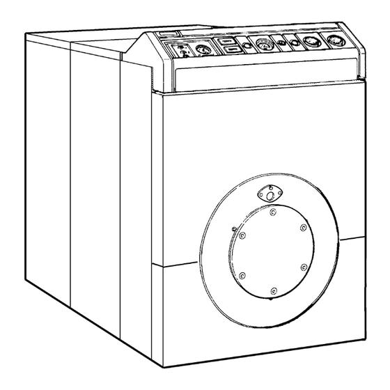
- Page 8 Boiler body (ill. 5) fig. 5...
- Page 9 41 3320252/0 Boiler burner door, finished 42 3800703/0 Burner door, complete 43 3535293/0 Mica disk Ø44 - Thickness 0.5 44 3340028/0 Pressure test point 45 3400885/0 Inspection window flange 46 3215253/0 Flange Ø340 - thickness 12 47 3401067/1 Door handle 48 3450582/0 Stud bolt M16x76 49 3410059/0 Boiler door hinge 50 3532088/0 Burner holder insulation...
- Page 10 Wiring diagram (ill. 6) Burner 1st stage regulating thermostat Burner 2nd stage regulating thermostat Burner switch Safety thermostat Burner 1st stage hour meter Burner 2nd stage hour meter Burner central panel Burner safety light 230 V 50 Hz fig. 6 Flue gas path fig.
-
Page 11: Installation
In particular, regulations regarding safety and the construction and location of flues should be observed. Base (ill. 9) The GN4 boiler does not require any special kind of foundation; a simple concrete base is sufficient, rein- forced if necessary with metal plates to facilitate positioning of the boiler. - Page 12 Connection to low temperature central heating system (ill. 10) The delivery circulation flow must be calculated with a t of between 10 C and 30 C. Delivery Return fig. 10...
- Page 13 Connection to traditional central heating sys- tem (ill. 11) Example: for GN4.09 (300 kW) A boiler recirculation pump must be fitted to prevent recirculation flow must be between faulty circulation in the generators. Also, the non- return valves must be fitted upstream of the return...
-
Page 14: Assembling The Boiler Body
ASSEMBLING THE BOILER BODY fig. 15 3 (fig. 15) Clean the cone inserts with solvent for grease. Using a soft brush, spread a thin layer of red lead (contained in the assembly kit) on the cone insert and its housing. fig. - Page 15 fig. 17 5 (fig. 17) Using the silicone included in the assem- bly kit, spread a thin strip around the sealing gasket housing (on both sides of the intermediate element). fig. 19 7 (fig. 19) Add the other two pieces C. fig.
- Page 16 fig. 23 9 (fig. 21-22-23) Insert the tie rod 1 between the two elements, fit the nut 3 on the threaded end, position the stop pin 2 on the tie rod hole at the end of the two elements and, by means of the spanner 4, tighten the unit until the two elements are perfectly joined.
- Page 17 Check that the flue gas seal between the elements is cor- rect. Ferroli S.p.A accepts no liability for damage to property or injuries to persons caused by leaks of water and flue gas from the boiler fig.
- Page 18 8 Elements Hole Detail of pipe union with screw 9 Elements 1115 Example for GN4.09 A1 = Section with flange 10 Elements C2 = Intermediate section with 2 holes B4 = End section with 4 holes 1245...
- Page 19 Positioning and fitting the diffuser pipe with connection to a traditional central heating sys- tem via the lower boiler coupling (fig. 31) fig. 31 17 (fig. 31) Fit the diffuser pipe “1” to the lower boiler coupling in the traditional version or to the upper fig.
- Page 20 fig. 33 fig. 34 19 (fig. 33) Fit the burner door, hinging it to the 20 (fig. 34) Secure the door by screwing the nuts supports by means of the pins “1”. “2” onto the stud bolts 1. 21 (fig. 35) Cover the boiler body with the sheet of rock wool provided, fix- ing it to the tie rods “1”...
-
Page 21: Assembling The Casing
ASSEMBLING THE CASING 22 (Ill. 36) Prepare the right and left sides, choosing the number of side panels according to the boiler dimensions. fig. 36 23 (fig. 37) Join the panels by means of the screws 1, washers 2 and nuts 3, reinforcing them at the bottom with the metal plates 4 secured with the screws 5. - Page 22 fig. 38 24 (fig. 38) Assemble the rear panels “1” on the stud bolts of the smokebox without fixing them. fig. 40 26 (fig. 40) Fix the side panels on the supports “1” from the rear by means of self-tapping screws. fig.
- Page 23 fig. 42 28 (fig. 42) Fit the instrument control panel, secur- ing it with the four self-tapping screws 1. Pass the four capillaries (thermometer, safety ther- mostat and regulating thermostats) through hole A and make the electrical connections accord- ing to the diagram in fig. 6. N.
- Page 24 fig. 46 fig. 44 30. (fig. 44) Fit the top front panel "1" and the 32 (fig. 46) Assemble the burner following the manu- bottom one "2" in their housings by means of facturer’s instructions. Connect a tube for cool- pins and springs.
-
Page 25: Checks
CHECKS REGULATION Before starting up for the first time Positioning the thermostats (ill. 47) Before starting up for the first time, it is good The thermostats are factory set to a minimum value practice to check that: of 30¡ C and maximum of 90 C. If you wish to alter a) the system is filled to the right pressure and has the range, proceed as follows: been correctly bled;... -
Page 26: Maintenance
MAINTENANCE Maintenance of the boiler must be performed by qualified personnel only. It is good practice to have the appliance serviced at least once a year, before the winter. Servicing must include not only cleaning of the boiler - correct opera- tion of all its control and safety devices and of the burner must also be checked, in addition to the condition of the flue gas outlet duct. - Page 28 ALL SPECIFICATIONS SUBJECT TO CHANGE Lichfield Road, Branston Industrial Estate, Burton Upon Trent, Staffordshire DE14 3HD Tel. 08707 282 885 - Fax 08707 282 886...
Need help?
Do you have a question about the GN4 and is the answer not in the manual?
Questions and answers