Advertisement
Available languages
Available languages
Quick Links
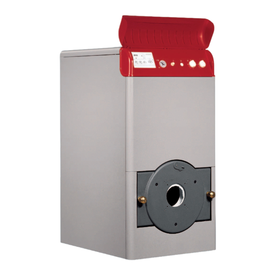
GN2 N
high-efficiency cast iron boiler for liquid fuels and/or gas
OPERATING, INSTALLATION AND MAINTENANCE INSTRUCTIONS
caldaia di ghisa ad alto rendimento per combustibili liquidi e/o gassosi
IT
ISTRUZIONI PER L’USO L’INSTALLAZIONE E LA MANUTENZIONE
chaudière en fonte a haut rendement pour combustibles liquides et/ou gazeux
FR
INSTRUCTIONS POUR L’INSTALLATION ET L’ENTRETIEN
caldera de fundición, de alto rendimiento para combustibles líquidos y/o gaseosos
ES
INSTRUCCIONES DE USO, INSTALACIÓN Y MANTENIMIENTO
verwarmingsketel in gietijzer met hoog rendement voor vloeibare en/of gasvormige brandstof
NL
AANWIJZINGEN VOOR HET GEBRUIK, DE INSTALLATIE EN HET ONDERHOUD
sivi ve/veya gaz yakitli yüksek ver‹ml‹
TR
DÖKÜM DÖLMLÖ KAZAN
Advertisement

Related Manuals for Ferroli GN2 N Series


Summary of Contents for Ferroli GN2 N Series
- Page 1 GN2 N high-efficiency cast iron boiler for liquid fuels and/or gas OPERATING, INSTALLATION AND MAINTENANCE INSTRUCTIONS caldaia di ghisa ad alto rendimento per combustibili liquidi e/o gassosi ISTRUZIONI PER L’USO L’INSTALLAZIONE E LA MANUTENZIONE chaudière en fonte a haut rendement pour combustibles liquides et/ou gazeux INSTRUCTIONS POUR L’INSTALLATION ET L’ENTRETIEN caldera de fundición, de alto rendimiento para combustibles líquidos y/o gaseosos INSTRUCCIONES DE USO, INSTALACIÓN Y MANTENIMIENTO...
- Page 2 GN2 N Dear Customer, Thank you for having chosen the GN2 N, an advanced-concept Ferroli boiler featuring cut- ENGLISH ting-edge technology, high reliability and constructional quality. Carefully read this manual and keep it for future reference. The GN2 N is a high-effi ciency heat generator for the production of hot water for heating purposes, suitable for operation with jet burners on gas or liquid fuel.
- Page 3 GN2 N 1. OPERATING INSTRUCTIONS 1.1 Control panel Ready for electronic control unit Thermohydrometer Safety thermostat Control thermostat, 2 Stages Line switch “0 - I - TEST” Burner lockout indicator light fi g. 1 1.2 Ignition Move the main switch 5 to position “I” to power the boiler and the burner. Refer to the burner manual for the operation of this device. 1.3 Setting Set the desired system temperature using the control thermostat 4.
- Page 4 GN2 N 2.1 Water connections Make the water connections to the appliance according to the indications shown both next to each fi tting and in Figure 2 of this booklet. The connections must be made in such a way that the pipes are not under stress. The safety valve must be fi tted in the central heating circuit, as close as possible to the boiler, without there being any obstructions or on-off devices between the boiler and the valve.
- Page 5 GN2 N Connect the panels together, using the screws 1, the washers 2 and the nuts 3, reinforcing the bottom parts using the blades 4 fastened with the screws 5. Loosen the nuts “A”. Insert the side fastening bracket “A” between nuts “A” and “B”. Fit the side to the bracket “A”...
- Page 6 All the adjustment, commissioning and maintenance operations must be performed by Qualifi ed Personnel, in compliance with the standards in force. FERROLI S.p.A. declines all liability for damage to persons and/or things deriving from the tampering with the appliance by unqualifi ed or unauthorised persons.
- Page 7 GN2 N 4. TECHNICAL SPECIFICATIONS Comb. Comb. Water Heat input gas+oil Heat output N° Water Operating chamber Body Ø chamber pressure (NHV) kW elem. content pressure pressure weight volume drop drop Model Dp mbar Dt 10 Dt 20 GN2 N 05 97,8 GN2 N 06 116,0...
- Page 8 GN2 N Gentile Cliente, La ringraziamo di aver scelto GN2 N, una caldaia Ferroli di concezione avan za ta, ITA LIA NO tec no lo gia al l’avan guar dia, elevata affi dabilità e qualità costruttiva. La pre ghia mo di leg ge re attentamente il pre sen te ma nua le e di conservarlo con cura per ogni riferimento futuro.
- Page 9 GN2 N 1. ISTRUZIONI D’USO 1.1 Pannello comandi Legenda Predisposizione centralina elettronica Termoidrometro Ter mo sta to di sicurezza Ter mo sta to di regolazione 2 Sta dio In ter rut to re di linea “0 - I - TEST” Lampada spia blocco bruciatore fi...
- Page 10 GN2 N 2.1 Collegamenti Idraulici Eseguire l’allacciamento idraulico dell’apparecchio rispettando le indicazioni poste in prossimità di ogni attacco e quelle riportate nella fi gura 2 di questo libretto. L’allacciamento deve essere fatto in modo che i tubi siano liberi da tensioni ed è d’obbligo montare la valvola di sicurezza sul circuito riscal- damento, in un punto il più...
- Page 11 GN2 N Collegare i pan nel li tra di loro, tra mi te le viti 1, le rondelle 2 ed i dadi 3, rinfor- zando la loro parte inferiore con le lame 4 fis sa te con le viti 5. Allentare i dadi "A"...
- Page 12 Tutte le operazioni di regolazione, messa in servizio e manutenzione devono essere effettuate da Personale Qualifi cato e di sicura qua li fi c- a zio ne, in conformità alle norme vigenti. FERROLI S.p.A. declina ogni responsabilità per danni a cose e/o persone derivanti dalla manomissione dell’apparecchio da parte di persone non qualifi cate e non autorizzate.
- Page 13 GN2 N 4. DATI TEC NI CI Portata termica Perdite Volume Perdite di Pressione Contenuto Potenza Peso gas+gasolio (PCI) N° Ø carico camera carico d'esercizio acqua termica corpo elem. camera comb. acqua comb. Modello Dp mbar Dt 10 Dt 20 GN2 N 05 97,8 GN2 N 06...
- Page 14 Nel solo caso in cui alla caldaia venga abbinato un bruciatore a marchio Ferroli, entro 30 giorni dalla messa in servizio il Cliente deve richiedere ad un Centro di Assistenza Autorizzato da Ferroli S.p.A. l’intervento gratuito per la verifica iniziale del prodotto e l’attivazione, tramite registrazione, della garanzia convenzionale che in questo caso avrà...
- Page 15 GN2 N Cher client, nous vous remercions d’avoir choisi GN2 N, une chaudière Ferroli de conception avancée, FRANÇAIS synonyme de technologie à l’avant-garde, fi abilité élevée et qualité de construction. Nous vous prions de lire attentivement ce livret d’instructions et de le conserver avec soin afi n de pouvoir vous y reporter si nécessaire.
- Page 16 GN2 N 1. MODE D’EMPLOI 1.1 Panneau de commandes Légende Place boîtier électronique Thermohydromètre Thermostat de sécurité Thermostat de régulation 2 éme stade Interrupteur de ligne Voyant blocage brûleur fi g. 1 1.2 Mise en marche Mettre l’interrupteur principal 5 sur «I» pour alimenter la chaudière et le brûleur. Se reporter au manuel du brûleur pour son fonctionnement. 1.3 Réglage Programmer la température voulue à...
- Page 17 GN2 N 2.1 Raccordements hydrauliques Effectuer le raccordement hydraulique de l’appareil en respectant les indications placées près de chaque raccord et celles indiquées dans la fi gure 2 de ce livret. Le raccordement doit être fait de façon à ce que les tuyaux ne subissent pas de tensions et il est obligatoire de monter la vanne de sécurité sur le circuit de chauffage, le plus près possible de la chaudière, sans aucun obstacle ou organe d’arrêt entre celle-ci et la vanne.
- Page 18 GN2 N Fixer les panneaux entre eux, à l’aide des vis 1, les rondelles 2 et les écrous 3, en renforçant leur partie inférieure avec les lames 4 fixées avec les vis 5. serrer les écrous «A» placer l’étrier de fixation des flancs «A» entre les écrous «A» et «B». fixer le côté...
- Page 19 Toutes les opérations de réglage, mise en marche et entretien doivent être effectuées par un technicien qualifi é, conformément aux normes en vigueur. FERROLI S.p.A. décline toute responsabilité pour les dommages aux choses et/ou aux personnes causés par une modifi cation de l’appareil exécutée par des personnes non qualifi ées et non agréées.
- Page 20 GN2 N 4. DONNÉES TECHNIQUES Puissance Pertes de Puissance thermique charge Volume Pertes de thermique N° Contenu Pression Poids gaz+fuel (PCI) Ø chambre chambre charge eau elem. de service corps de comb. combust. Modèle Maxi Mini Maxi Mini Dp mbar Dt 10 Dt 20 GN2 N 05...
- Page 21 2 ans suivant l'acquisition. FERROLI France n'étant pas le vendeur final vis-à-vis du consommateur, elle entend toutefois supporter sa responsabilité lorsqu'elle est engagée selon sa propre garantie conventionnelle, fournie par son réseau de stations techniques agréées aux conditions rapportées ci-dessous.
- Page 22 GN2 N Estimado cliente, le agradecemos de haber elegido GN2 N, una caldera Ferroli de concepción avanzada, ESPAÑOL tecnología de vanguardia, de elevada fi abilidad y de calidad constructiva. Le rogamos encarecidamente leer atentamente el presente manual y de con ser var lo cuidadosamente para cualquier consultación futura.
- Page 23 GN2 N 1. INSTRUCCIONES DE USO 1.1 Cuadro de mandos Leyenda Predisposición de la centralita electrónica Termohidrómetro Termostato de seguridad Termostato de regulación 2a etapa Interruptor de línea Lámpara chivato de bloqueo del quemador fi g. 1 1.2 Encender Posicionar el interruptor principal 5 en “I” para alimentar la caldera y el quemador. Consúltese el manual del quemador respecto de su fun- cionamiento.
- Page 24 GN2 N 2.1 Conexiones hidráulicas Realizar la conexión hidráulica del equipo respetando las indicaciones colocadas cerca de cada enganche y de aquéllas mostradas en la fi gu ra 2 de este manual. La conexión debe ser realizada cerciorándose que los tubos estén libres de tensiones; es obligatorio montar la válvula de seguridad en el cir cui to de calentamiento, en el punto más cercano posible de la caldera, sin que entre ésta y la válvula se encuentren obstrucciones o algún mecanismo de interceptación.
- Page 25 GN2 N Unir entre sí los paneles mediante los tornillos 1, las arandelas 2 y las tuercas 3, reforzando su parte inferior con las hojas 4, fijadas con los tornillos 5. Aflojar las tuercas «A» Poner la brida de fijación de los flancos «A» entre las tuercas «A» y «B». Fijar el flanco en la brida «A»...
- Page 26 FERROLI S.p.A. declina cualquier responsabilidad por lesiones causadas a personas y/o daños a cosas, imputables a manipulación del equipo por parte de personas técnicamente no cualifi cadas y no autorizadas a su uso.
-
Page 27: Table Of Contents
GN2 N 4. DATOS TÉCNICOS Capacidad térmica Pérdidas Volumen Pérdida de Presión Contenido Potencia Peso gas + gasóleo (PCI) N° Ø carga cámara carga agua de servicio agua térmica cuerpo elem. cámara comb. comb. Modelo Dp mbar Dt 10 Dt 20 GN2 N 05 97,8 GN2 N 06... - Page 28 Las posibles reclamaciones deberán efectuarse ante el organismo competente en esta materia. Sede Central y Fábrica: Polígono Industrial de Villayuda Apartado de Correos 267 - 09007 Burgos Tel. 947 48 32 50 Fax 947 48 56 72 e.mail: ferroli@ferroli.es Certificado de funcionamiento Llene por favor la cupón unida http//www.ferroli.es Dirección Comercial: Avda.
-
Page 29: Gn2 N
Wij danken u om te hebben gekozen voor GN2 N, een geavanceerde verwarmin- NEDERLANDS gsketel van Ferroli die zowel avant-gardetechnologie als een hoge betrouwbaarheid en kwaliteit biedt. Wij verzoeken u deze handleiding aandachtig door te nemen en zorgvuldig te bewaren voor latere raadplegingen. -
Page 30: Gn2 N
GN2 N 1. GEBRUIKSAANWIJZINGEN 1.1 Bedieningspaneel Legende Voorziening elektronische verdeelkast Thermowaterstandsmeter Veiligheidsthermostaat Regelthermostaat 2° Stadium Lijnschakelaar Controlelampje blokkeren brander fi g. 1 1.2 Ontsteking Breng de hoofdschakelaar 5 in de stand “I” om de verwarmingsketel en brander te voeden. Voor de werking van de brander, de relatieve handleiding raadplegen. - Page 31 GN2 N 2.1 Aansluitingen op de waterleiding Voer de aansluiting van het apparaat op de waterleiding uit, met inachtneming van de aanwijzingen vlakbij elk aansluitpunt en op fi guur 2 in deze handleiding. De aansluiting wordt op zodanige wijze uitgevoerd dat de buizen niet worden belast. Het is verplicht een veiligheidsklep te monteren op het verwarmingscircuit, zo dicht mogelijk bij de verwarmingsketel, zonder obstakel of onderscheppingsinrichting tussen de ketel en de klep.
- Page 32 GN2 N Verbind de panelen onderling, met behulp van de schroeven 1, de rondsels 2 en de moeren 3. Verstevig de onderkant van de panelen met de ijzers 4 vastgezet met de schroeven 5. De moeren “A” aanzetten De staaf voor de bevestiging van de flanken “A” tussen de moeren “A” en “B” brengen. De rechterflank bevestigen aan de staaf “A”...
- Page 33 Alle handelingen relatief aan de regelingen, inwerkingstelling en onderhoud dienen te worden uitgevoerd door vakbekwaam en opgeleid per- soneel, overeenkomstig de geldende nomen. FERROLI S.p.A wijst elke verantwoordelijkheid af voor schade toegebracht aan voorwerpen en/of personen, voortvloeiend uit de wijziging van het apparaat vanwege niet bekwame en niet bevoegde personen.
-
Page 34: Gn2 N 05
GN2 N 4. TECHNISCHE GEGEVENS Warmte- Thermich bereik Thermisch Omvang Aantal verlies Warmteverlies Gewicht gas+gasolie vermogen Waterinhoud Bedrijfsdruk Ø verbrandin- elem. verbrandin- water lichaam (PCI) kW gskamer gskamer Model Dp mbar Dt 10 Dt 20 GN2 N 05 97,8 GN2 N 06 116,0 GN2 N 07 136,9... - Page 35 De¤erli mü©terimiz, ‹leri teknolojinin ürünü olan ve güvenilirlik ile kaliteyi her zaman kendine hedef TÜRKÇE seçmi© olan Ferroli’nin üretti¤i GN2 N kazan›n› seçmi© oldu¤unuz için te©ekkür ederiz.Sizlere sundu¤umuz bu k›lavuzu dikkatle okuman›z› ve özenle saklaman›z› rica ediyoruz. GN2 N yüksek verimli bir ›s› jeneratörü olup ›s›tma için s›cak su üreten, gaz veya s›v›...
- Page 36 GN2 N KULLANIM TAL‹MATLARI 1.1. Kumanda Paneli Ekopanel ba¤lant› yeri Termohidrometre Emniyet termostat› 2. a©amal› ayar termostat› Açma-Kapama anahtar› © ekil 1 1.2 Ate©leme Ana elektrik ak›m anahtar›n› (5) kazan ve brülörü beslemek için “I“ konumuna çevirin. ‹lgili çal›©t›rma ©ekli için k›lavuza bak›n›z.
- Page 37 GN2 N 2.1 Hidrolik ba¤lant› Bu k›lavuzun 2 no.lu resminde belirtildi¤i kurallara uygun ©ekilde ilgili yerlerle ba¤lant›lar› yap›n. Ba¤lant›, borularda gerilim hatt› olmadan yap›lmal› ve emniyet valfinin cihaza en yak›n noktas›na cihaz ile aras›nda herhangi bir engelleyici olmadan ›s›tma devrine monte edilmesi gerekmektedir. Cihazda genle©me tank›...
- Page 38 GN2 N D Vidalar (1), rondelalar (2) ve somunlar (3) arac›l›¤›yla panelleri kendi aralar›nda birle©tirin. Alt k›sm› vidalarla (5) kesici uç sayesinde güçlendirin. E “A“ somunlar›n› gev©etin. F “A“ ve “B“ somunlar› aras›na “A“ kenarlar› sabitleme somunlar›n› ilave edin. G “A“ üzengi üzerine yan taraf› “B“ vidalar›yla sabitleyin (sa¤ taraf) G ©›kk›nda belirtilen i©lemleri Sol taraf içinde uygulay›n.
- Page 39 GN2 N 3. SERV‹S VE BAKIM Servis ve bak›m› kapsayan tüm de¤i©tirme ve ayar i©lemleri Yetkili ki©iler taraf›ndan normlara uygun olarak yap›lmal›d›r. Ferroli A.®. konusunda deneyimli ve de yetkili olmayan ki©iler taraf›ndan yap›lan müdaheleler sonucunda ki©i veya e©yalara olabilecek zarar›n sorumlulu¤unu kabul etmez.
- Page 40 GN2 N 4. TEKN‹K VER‹LER Ø Modello Dp mbar Dt 10 Dt 20 GN2 N 05 97,8 GN2 N 06 116,0 GN2 N 07 136,9 GN2 N 08 156,5 GN2 N 09 176,0 1087 GN2 N 10 195,6 1197 GN2 N 11 215,2 1307 GN2 N 12...
- Page 41 Cihazın arızasının 10 iş günü içinde (Pazar günleri 5. Voltaj düşüklüğü veya fazlalığı, topraksız priz kullanılması, hatalı elektrik iş günü değildir) giderilmemesi halinde, Ferroli, malın tamiri başlayıncaya kadar, tesisatından meydana gelen hasar ve arızalar, benzer özelliklere sahip başka bir malı tüketicinin kullanımına tahsis etmek zorundadır.
- Page 44 FERROLI S.p.A. Via Ritonda 78/a 37047 San Bonifacio - Verona - ITALY www.ferroli.com Made in Italy - Fabbricato in Italia - Fabriqué en Italie Fabricado en Italia - Vervaardigd in Italië - italya’da üretilmiştir...
Need help?
Do you have a question about the GN2 N Series and is the answer not in the manual?
Questions and answers