
Related Manuals for Ferroli GNK1 Series


Summary of Contents for Ferroli GNK1 Series
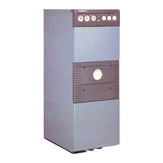
- Page 1 CAST IRON SECTIONAL BOILER FOR HEATING AND PRODUCTION DOMESTIC HOT WATER GNK1 INSTALLATION AND USE INSTRUCTIONS...
-
Page 3: Table Of Contents
INDEX 1. Technical informations 2. Dimensions and technical data 3. Packing and shipping details 4. Installation 5. Checking 6. Service 7. Optional 8. Boiler components... -
Page 4: Technical Informations
1. TECHNICAL INFORMATIONS 1.01 Introduction GNK1 boiler is a new heating generator with high efficiency, for central heating system as well sanitary hot water production suitable for burners using oil or gas. The boiler body is built by cast iron sections joined togheter by mean of biconical nipples and tie rods. - Page 5 Summer /Winter switch on the «SUMMER» setting When the switch has been set to this position, the plant will produce hot sanitary water only and the relative heating circuit will be kept permanently off. The burner and circulator will therefore only operate to maintain the temperature of the sanitary water whilst this is being used or during long periods at a standstill.
-
Page 6: Dimensions And Technical Data
2. DIMENSIONS AND TECHNICAL DATA 2.01 Dimensions and technical data (fig. 2 - tables 1) 6 5 4 Fig. 2 1 Thermomanometer boiler 6 Switch Summer/Winter a1 Flow 1" 1/2 2 Thermometer boiler 7 Security thermostat a2 Return 1" 3 Timer sochet 8 Circulating pump boiler a3 Boiler drain 1/2"... - Page 7 t s i ∆ N.B.: Max. water temperature for the heating system is 110° C. NOTE: When priority ends with high temperature water in the boiler, the thermal inertia which develops when the circulator stops could inhibit the boiler itself (total switch-off) owing to activation of the safety thermostat at 100˚C.
- Page 8 2.03 Hydraulic diagram Flow Return Hot sanitary water outlet Recirculation Cold sanitary water inlet Fig. 4 1 Automatic air vent 13 Thermometer boiler 2 Safety valve 14 Thermometer boiler 3 Cock drain 15 Safety thermostat 4 Coil 16 Circulating pump thermostat 5 Boiler 17 Boiler shell 6 Safety thermostat boiler...
-
Page 9: Installation
5 A max must be provided. N.B. - Appliance must be earthed. It is recommended to connect the boiler to a good electric earth system. FERROLI could not be considered responsable for any kind of damage to Persons or things caused by failure of earthing... - Page 10 4.02 Connection to the water main Connect the appliance to the water main in compliance with the indications near each fitting and those listed in fig. 2 of this handbook. Connections must be made so that the pipes are free from tensions. It is essential to mount the safety valve on the heating circuit and on the sanitary circuit, using the relative fittings in the boiler.
- Page 11 ELECTRIC DIAGRAM 230V 50 Hz S = DIAGRAM TRC = THERMOSTAT CONTROL BOILER TRB = THERMOSTAT BOILER TC = THERMOSTAT CIRCULATING PUMP CB = CIRCULATING PUMP CR = CIRCULATING TA = ROOM THERMOSTAT (NOT SUPPLIED) TS = SAFETY THERMOSTAT EI = SUMMER-OFFWINTER SELECTOR B = BURNER FU = FUSIBLE 5A OP = PROGRAMMER CLOCK (OPTIONAL)
-
Page 12: Checking
5. TESTING 5.01 Before the first light of the boiler Before the first light of the boiler follow these check list: a) check the system and the boiler is filled with water at the right pressure; b) check against any leakage of water fuel; c) check that the correct electric power is supplied to the unit;... -
Page 13: Service
6.01 Boiler cleaning Cut out electric power. Cut out the panec 1, 2 and 3 (fig. 7). Clean the boiler internal parts. Check the flue duct and if necessary clean it. The burner service must be done according the Manufacture Instructions. 6.02 Boiler cleaning Shut the sanitary water on-off valve at the heater inlet and completely drain the water from the heater itself. -
Page 14: Optional
7. OPTIONALS 7.01Programmer clock 1 - Remove plug «A» from the control panel. 2 - Fit clock «B» into its housing. 3 - Fix with screws «C». 4 - Remove the jumper between terminals 11-12 and connect the clock cables as shown in the wiring diagram. - Page 15 7.02 Programming Turn the program disk in a clockwise direction to set the time just like a normal clock. Lower the mobile rods to select the activation times can be at a frequency of 15 minutes a time (each mobile rod). The lever switch near the pointers enables the following operations: 1 - Set the lever to position «I»...
-
Page 16: Boiler Components
8. BOILER COMPONENTS Fig. 10... - Page 17 POS. COD. DESCRIPTION 33004700 FRONT SECTION 33004710 REAR SECTION 33004720 MIDDLE SECTION 33100600 REDUCTION COLLAR 31208180 ANGLE DX 31208190 ANGLE SX 33202120 UPPER DOOR 33202100 SPY HOLE COVER 33202280 BURNER DOOR 33400700 PROBES POCKET 33600340 REDUCTION 34000600 REDUCTION 1" - 1/2" 34000610 PLUG 34008750...
- Page 18 Fig. 11...
- Page 19 POS. COD. DESCRIPTION 37026530 RIGHT SIDE PANEL 37026540 LEFT SIDE PANEL 37026550 COVER 37026560 UPPER FRONT PANEL 37026570 LOW FRONT PANEL 38505621 COMPLETE CONTROL PANEL 38315370 CARD ELECTRIC 31133680 REAR PANEL 31133690 REAR PANEL 31133700 REAR PANEL 31000210 SPRING 35000640 TUBE BRUSH 35001820 PLUG...
- Page 20 37047 San Bonifacio - VR - Italia tel. 045/6139411 • tlx. 480172 fax 045/6100233 - 6100933...
Need help?
Do you have a question about the GNK1 Series and is the answer not in the manual?
Questions and answers