
Related Manuals for Ferroli GN 3


Summary of Contents for Ferroli GN 3
- Page 1 INSTALLATION AND USE INSTRUCTIONS GN 3 HIGH EFFICIENCY CAST IRON BOILER FOR LIQUID and/or GAS FUELS...
-
Page 3: Table Of Contents
Your new GN3 has been built according to highly advanced technologies using strong and reliable materials. Please follow our advice carefully and you will certainly get the best from your boiler. Ferroli quality also covers the technical and functional features of the boiler which comply with the current provisions in merit. -
Page 4: General Information
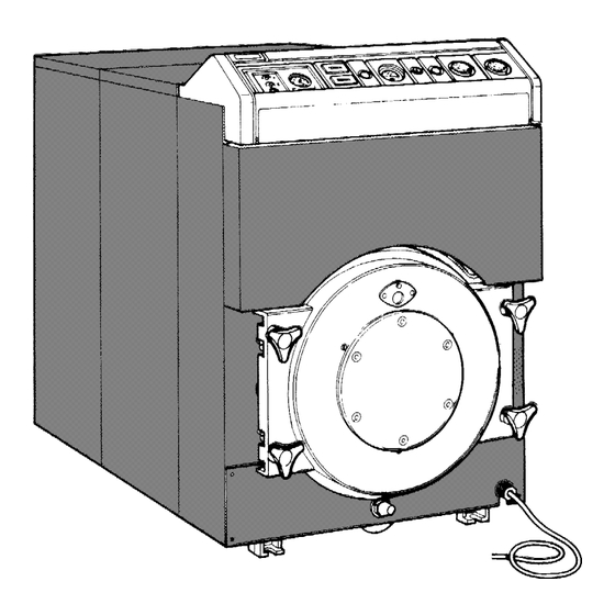
GENERAL INFORMATION Description Packing (fig. 2) Boiler GN3 is a new highly efficient heat generator. It Boiler GN3 can be supplied in two types of pack: with the produces hot water for heating purposes and is able to boiler shell assembled or in parts: operate with either liquid and/or gas fuelled burners. -
Page 5: Features
FEATURES Technical brief (fig. 3) Fig. 3 1. Electronic plant (optional) 8. 2nd burner stage adjuster thermostat 2. 1st burner stage operation hour counter 9. 1st burner stage adjuster thermostat 3. 2nd burner stage operation hour counter 10. Pressure tap connection in combustion chamber 4. - Page 6 (fig. 4) Boiler shell Fig. 4 33004552 FRONT ELEMENT FN. 33004570 INTERMEDIATE ELEMENT FN. 26d 37401650 COMP.CYLINDER FOR COMB.CHAMBER - 9 elem. 33004910 INTERMEDIATE ELEMENT (LOW HEIGHTS) FN. 26e 37401660 COMP.CYLINDER FOR COMB.CHAMBER -10 elem. 33004580 INTERMEDIATE ELEMENT WITH LEGS FN. 37401660 COMP.CYLINDER FOR COMB.CHAMBER -11 elem.
- Page 7 COMPL.COMPON.COVER TYPE 1 (6-9-13 elem.) 37025140 COMPL.COMPON.COVER TYPE 2 (6-9-10-11-13-14 elem.) 37025150 COMPL.COMPON.COVER TYPE 3 (7-11-12 elem.) 31134530 COMPLETE REAR WALL 38503630 FERROLI TYPE DOUBLE CORE HITCH 38200860 COMPLETE INSTRUMENT PANEL 38701280 COMPLETE KNOB FOR THERMOSTAT 36401210 PROBE TR2 540499 C.1500 PVC 3CNT 36401450 PROBE LS 541577 C.1500 PVC 110 C...
- Page 8 Wiring diagram (fig. 6) Load loss diagram (fig. 7) Fig. 6 TR1 1st burner stage adjuster thermostat TR2 2nd burner stage adjuster thermostat Fig. 7 Burner switch STB Safety thermostat BZ1 1st stage burner hour counter BZ2 2nd stage burner hour counter Burner plant panel SB Burner safety warning light Fumes route (fig.
-
Page 9: Installation
1820 2050 Always connect the boiler to a good grounding system. Soundproofed base FERROLI S.p.A. declines all responsibility for damages to persons and/or property caused by failure to connect the appliance to a good grounding system. Hydraulic connection The hydraulic connections of the boiler should be accom- plished in compliance with the indications given near each union and those included in the Technical Brief. - Page 10 Heating plant installation (fig. 11). Burner operation must be linked to that of the recircula- If there is a boiler recirculating pump, it is obligatory to tion pump. It must only operate if the pump operates. As mount non-return valves upstream of the return union to an accessory, a flow rate monitoring device in series with prevent parasitic circulations in the generators.
-
Page 11: Assembling The Boiler Shell
ASSEMBLY Element assembly layout (fig. 12) Fig. 12 MOD. FRONT INT. ELEMENT INT. ELEMENT INT. ELEMENT REAR ELEMENT ELEMENT WITH SH. FINS WITH LEGS COD.3300455/2 COD. 3300491/0 COD. 3300458/0 COD. 3300457/0 COD. 3300456/0 GN3 06 GN3 07 GN3 08 GN3 09 GN3 10 GN3 11 GN3 12... - Page 12 Boiler shell Fig. 15 3. (Fig. 15) Clean the links with grease solvent. Using the package in the assembly kit, spread a light coating of minium on the twin-cone and its housing, using a soft brush. Fig. 13 1. (Fig. 13) Use a 15 mm. wooden strip to shim the rear element.
- Page 13 Fig. 19 Fig. 17 5. (Fig. 17) Using the packet of silicone included in the assembly kit, spread a light strip of this product in the retention seal housing (on both sides of the intermediate element). 6. (Fig. 18) Starting from point A, mount the retention seal in its housing.
- Page 14 Fig. 22 Fig. 20 8. (Fig. 20) Place the first intermediate element near the rear one, after having prepared it as described for the rear element itself (points 3 - 4 - 5 - 6 and 7). Also add the retention seal from point C through to point D.
- Page 15 Fig. 26 as to crush them. 13. (Fig. 26) Mount the following parts on the front side of Fig. 24 the boiler shell: * Four stud bolts 1 (M12x80) of the upper door. 10. Proceed as described in the previous paragraph until * Two stud bolts 2 (M12x135) of the door closing handw- all the elements forming the boiler shell have been heels.
- Page 16 Composition Water Distribution Pipe Spring clip GN3.06 490.0 HOLE GN3.07 Example for GN3.09 A1 = Flange section GN3.08 with 1 hole 1035 C2 = Middle section with 2 holes GN3.09 B4 = End section with 4 holes 1168 GN3.10 1301 GN3.11 1434 GN3.12...
-
Page 17: Water
Now check that the fumes seal between the elements is correct. Ferroli S.p.A. declines all responsibility for damage to persons or property caused by fumes and water leaks from the boiler due to assembly errors or negligent seal inspections. -
Page 18: Assembling The Casing
Fig. 34 21. (Fig. 34) Cover the boiler shell with the supplied sheet of mineral wool, fixing it to rods 1 (Fig. 24) and using clips 7 included in the assembly kit. CASING ASSEMBLY Fig. 32 19. (Fig. 32) Mount the lower door of the burner, hinging it to support 3 (Fig. - Page 19 23. (Fig. 36) Mount bar 2 on upper rods 1 (Fig. 24) and fix it with nuts 3. 6 elem. — — — 7 elem. 1040 — — — 8 elem. 1186 — 9 elem. 1316 — 10 elem. 1446 1072 —...
- Page 20 Fig. 38 Fig. 40 25. (Fig. 38) Connect the panels together using screws 1, washers 2 and nuts 3, reinforcing their lower part with bars 4 fixed with screws 5. 26. (Fig. 38) Slacken knobs 8 on the right side of the boiler together with the two screws 4 fixing door support 3.
- Page 21 Fig. 43 Fig. 41 28. (Fig. 41) Fix the right side panel to the rear panel using the three screws 1. 29. (Fig. 42) Slacken the two screws 1 on the left-hand side of the boiler and mount the left side panel, checking that the machined slots fit into their correct positions.
- Page 22 Fig. 46 34. (Fig. 46) Mount the control panel, fixing it with the four self-threading screws 1. Allow the four wires (thermometer, safety thermostat and regulating thermostat) to pass through hole A and make the electrical connections as indicated in the diagram of fig.
- Page 23 Fig. 48 Fig. 50 36. (Fig. 48) Mount the upper front panel. 38. (Fig. 50) Mount the burner according to the Manufac- turer’s instructions. Also connect a tube to cool the boiler porthole to the air tap of the burner (A). Fig.
-
Page 24: Inspections
INSPECTIONS ADJUSTEMENTS Before initial ignition Thermostat positioning (fig. 51) Before initial ignition, it is advisable to check that: The thermostats are preset in the factory to a minimum a) the system has been filled at the correct pressure and value of 30 C and a maximum value of 90 C. Proceed in is well vented;... -
Page 25: Servicing
SERVICING Boiler maintenance must only be carried out by Qualified Cleaning the boiler Personnel. 1. Switch off the boiler power supply. It is advisable to check the equipment at least once a 2. (Fig. 52) Remove upper front panel 1. year, before the winter season. - Page 28 37047 SAN BONIFACIO - VR - Italy tel. 045/6139411 - tlx. 480172 Fax 045/6100233 - 6100933...
Need help?
Do you have a question about the GN 3 and is the answer not in the manual?
Questions and answers