Table of Contents
Advertisement
Quick Links
Advertisement
Table of Contents

Subscribe to Our Youtube Channel
Related Manuals for Supero C7P67


Summary of Contents for Supero C7P67
- Page 1 C7P67 USER’S MANUAL Revision 1.0...
- Page 2 The information in this User’s Manual has been carefully reviewed and is believed to be accurate. The vendor assumes no responsibility for any inaccuracies that may be contained in this document, and makes no commitment to update or to keep current the information in this manual, or to notify any person or organization of the updates.
-
Page 3: About This Motherboard
About This Motherboard C7P67 supports a single Intel® 2nd Generation Core i3/i5/i7 processor in an LGA 1155 socket. With the Intel® P67 Express chipset built in, the C7P67 motherboard offers substantial enhancement in system performance and storage capability for high performance system platforms in a sleek package. Please refer to our website (http://www.supermicro.com/products/) for processor and memory... - Page 4 C7P67 User’s Manual Conventions Used in This Manual Pay special attention to the following symbols for proper motherboard installation and to prevent damage to the system or injury to yourself: Danger/Caution: Instructions to be strictly followed to prevent catastrophic system failure or to avoid bodily injury,...
-
Page 5: Contacting Supermicro
Contacting Supermicro Contacting Supermicro Headquarters Address: Super Micro Computer, Inc. 980 Rock Ave. San Jose, CA 95131 U.S.A. Tel: +1 (408) 503-8000 Fax: +1 (408) 503-8008 Email: marketing@supermicro.com (General Information) support@supermicro.com (Technical Support) Web Site: www.supermicro.com Europe Address: Super Micro Computer B.V. Het Sterrenbeeld 28, 5215 ML 's-Hertogenbosch, The Netherlands Tel:... -
Page 6: Table Of Contents
C7P67 User’s Manual Table of Contents Preface Chapter 1 Introduction Overview ......................1-1 Chipset Overview ................... 1-9 Special Features ................... 1-10 PC Health Monitoring ..................1-10 ACPI Features ....................1-11 Power Supply ....................1-11 Chapter 2 Installation Static-Sensitive Devices .................. 2-1 Precautions ..................... 2-1 Unpacking ....................... - Page 7 Table of Contents NIC1/NIC2 (LAN1/LAN2) ................2-20 Overheat (OH)/Fan Fail ................2-20 Reset Button ................... 2-21 Power Button ................... 2-21 Connecting Cables ..................2-22 ATX Main PWR & CPU PWR Connectors ..........2-22 Fan Headers ..................... 2-23 Chassis Intrusion ..................2-23 Internal Buzzer ..................
- Page 8 BIOS Error Beep Codes ................. A-1 Appendix B Software Installation Instructions Installing Drivers ....................B-1 Confi guring Supero Doctor III ................. B-2 Appendix C BIOS Recovery Recovery Process from a USB Device/Drive (Recommended Method) ..C-1 Part 1: Boot Sector Recovery Process ............C-1 Part 2: BIOS Reprogramming (Re-Flashing) ..........C-2...
-
Page 9: Chapter 1 Introduction
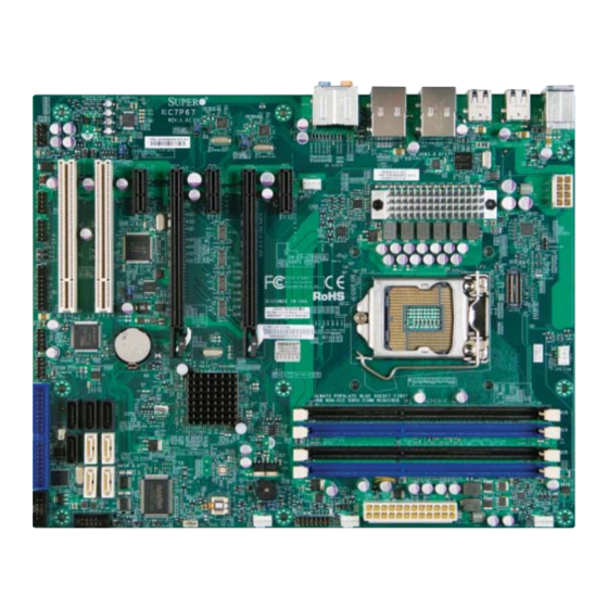
Chapter 1: Introduction Chapter 1 Introduction Overview Checklist Congratulations on purchasing your computer motherboard from an acknowledged leader in the industry. Supermicro boards are designed with the utmost attention to detail to provide you with the highest standards in quality and performance. Please check that the following items have all been included with your motherboard. - Page 10 C7P67 User’s Manual Motherboard Image (C7P67 Shown) Note: All graphics shown in this manual were based upon the latest PCB Revision available at the time of publishing of the manual. The motherboard you've received may or may not look exactly the same as the graphics...
- Page 11 Chapter 1: Introduction C7P67 Motherboard Layout HD AUDIO LAN2 LAN1 USB13/10 KB/Mouse USB11/12 Audio CTRL LAN CTRL USB8/9 LAN CTRL USB3.0 0/1 USB 2.0 0/1 JHD_AC1 USB 3.0 CTRL JPW2 FAN4 C7P67 Rev. 1.01 JI2C2 JI2C1 CATERR_LED1 JITP1 JTPM1 LGA1155...
-
Page 12: Jumper Description
C7P67 User’s Manual C7P67 Quick Reference KB/Mouse LAN 1 LAN 2 SPIDF-Out USB11/12 USB8/9 JHD_ACI JPAC1 Slot4 Slot5 Slot6 HD Audio Fan4 USB3.0 0/1 USB10/13 USB2.0 0/1 SPIDF-In Slot3 JPL2 JPL1 Slot7 Audio FP HD AUDIO LAN2 LAN1 USB13/10 KB/Mouse... - Page 13 USB (2.0) 0/1, 8/9, 11/12, 13/10 Backpanel USB 2.0 Ports 0/1, 8/9, 11/12, 13/10 USB (3.0) 0/1 Backpanel USB 3.0 Ports 0/1 USB2/3, USB4/5 Front Accessible USB Connections 2/3, 4/5 C7P67 LED Indicators Description Color/State Status LED1 Onboard Standby PWR LED...
-
Page 14: Motherboard Features
C7P67 User’s Manual Motherboard Features Intel® 2nd Generation Core i3/i5/i7 processor in an LGA1155 socket. Memory Four (4) SDRAM slots support up to 32 GB of DDR3 Unbuffered, Non-ECC 1333/1066 memory Supports dual-channel memory bus DIMM sizes UDIMM 1 GB, 2 GB, 4GB, and 8GB Chipset Intel®... - Page 15 Modulation) fan speed control Low noise fan speed control System Management PECI (Platform Environment Confi guration Interface) 2.0 support System resource alert via Supero Doctor III SuperoDoctor III, Watch Dog, NMI Chassis Intrusion header and detection CD Utilities BIOS fl ash upgrade utility Drivers and software for Intel®...
-
Page 16: System Block Diagram
C7P67 User’s Manual C7P67 Block Diagram SVID VRM 12 PCIe2.0_x8 INTEL LGA1155 PCIe x16 SLOT #6 5.0GT/s 4 UDIMM (Socket-H2) PCIe2.0_x8 DDR3 (CH1) DIMM1B 5.0GT/s DIMM1A (Blue) 1333/1066MHz AS Media PCIe2.0_x8 PCIe2.0_x8 PCIe x8 SLOT #4 Switch VRD12 5.0GT/s DDR3 (CH2) DIMM2B 5.0GT/s... -
Page 17: Chipset Overview
Chapter 1: Introduction Chipset Overview The C7P67 supports a single Intel® 2nd Generation Core i3/i5/i7 processor in the LGA 1155 Socket. Built upon the functionality and the capability of the P67 Express chipset, the motherboard provides substantial enhancement to system performance and storage capability for high performance platforms in a sleek package. -
Page 18: Special Features
System Resource Alert This feature is available when the system is used with Supero Doctor III in the Windows OS environment or used with Supero Doctor II in Linux. Supero Doctor is used to notify the user of certain system events. For example, you can... -
Page 19: Acpi Features
Chapter 1: Introduction also confi gure Supero Doctor to provide you with warnings when the system temperature, CPU temperatures, voltages and fan speeds go beyond predefi ned thresholds. ACPI Features ACPI stands for Advanced Confi guration and Power Interface. The ACPI specifi ca- tion defi... - Page 20 C7P67 User’s Manual fi lter to shield the computer from noise. It is recommended that you also install a power surge protector to help avoid problems caused by power surges. 1-12...
-
Page 21: Chapter 2 Installation
Chapter 2: Installation Chapter 2 Installation Static-Sensitive Devices Electrostatic-Discharge (ESD) can damage electronic com ponents. To avoid dam- aging your system board, it is important to handle it very carefully. The following measures are generally suffi cient to protect your equipment from ESD. Precautions •... -
Page 22: Processor And Heatsink Installation
C7P67 User's Manual Processor and Heatsink Installation Warning: When handling the processor package, avoid placing direct pressure on the label area of the fan. Notes: Always connect the power cord last, and always remove it before add- ing, removing or changing any hardware components. Make sure that you install the processor into the CPU socket before you install the CPU heatsink. - Page 23 Chapter 2: Installation Gently lift the load lever to open the load plate. Remove the plastic cap. Use your thumb and your index fi nger to hold the CPU at the North center edge and the South center edge of the CPU. North Center Edge South Center Edge Align the CPU key that is the semi-circle cutouts against the socket keys.
- Page 24 C7P67 User's Manual Do not rub the CPU against the surface or against any pins of the socket to avoid damaging the CPU or the socket.) With the CPU inside the socket, inspect the four corners of the CPU to make sure that the CPU is properly installed.
-
Page 25: Installing An Active Fan Cpu Heatsink
Chapter 2: Installation Installing an Active Fan CPU Heatsink Locate the CPU Fan power connec- tor on the motherboard. (Refer to the layout on the right for the CPU Fan location.) Position the heatsink so that the heatsink fan wires are closest to the Thermal Grease CPU fan power connector and are not interfered with other compo-... - Page 26 C7P67 User's Manual Align the four heatsink fasten- ers with the mounting holes on the motherboard. Gently push the pairs of diagonal fasteners (#1 & #2, and #3 & #4) into the mounting holes until you hear a click. Also,...
-
Page 27: Removing The Heatsink
Chapter 2: Installation Removing the Heatsink Warning: We do not recommend that the CPU or the heatsink be removed. However, if you do need to remove the heatsink, please follow the instructions be- low to remove the heatsink and to prevent damage done to the CPU or other components. -
Page 28: Installing Ddr3 Memory
C7P67 User's Manual Installing DDR3 Memory Note: Check the Supermicro website for recommended memory mod- ules. CAUTION Exercise extreme care when installing or removing DIMM modules to prevent any possible damage. DIMM Installation Insert the desired number of DIMMs into the memory slots, starting with DIMM1A (Channel 1, Slot A). -
Page 29: Memory Support
Chapter 2: Installation Memory Support The C7P67 supports up to 32GB of Unbuffered (UDIMM) DDR3 Non-ECC 1333/1066 MHz in 4 memory slots. Populating these DIMM modules with a pair of memory modules of the same type and same size will result in interleaved memory, which will improve memory performance. - Page 30 C7P67 User's Manual Possible System Memory Allocation & Availability System Device Size Physical Memory Remaining (-Available) (4 GB Total System Memory) Firmware Hub fl ash memory (System BIOS) 1 MB 3.99 Local APIC 4 KB 3.99 Area Reserved for the chipset 2 MB 3.99...
-
Page 31: Motherboard Installation
Philips Screws (9 Pieces) (9 Pieces) Location of Mounting Holes C7P67 Rev. 1.01 Caution: 1) To avoid damaging the motherboard and its components, please do not use a force greater than 8 lb/inch on each mounting screw during motherboard installation. 2) Some components are very close to the mounting holes. -
Page 32: Installing The Motherboard
C7P67 User's Manual Installing the Motherboard Install the I/O shield into the chassis. Locate the mounting holes on the motherboard. (See the previous page.) Locate the matching mounting holes on the chassis. Align the mounting holes on the motherboard against the mounting holes on the chassis. -
Page 33: Connectors/Io Ports
KB/Mouse USB11/12 Audio CTRL LAN CTRL USB8/9 LAN CTRL USB3.0 0/1 USB 2.0 0/1 JHD_AC1 USB 3.0 CTRL JPW2 FAN4 C7P67 Rev. 1.01 JI2C2 JI2C1 CATERR_LED1 JITP1 JTPM1 LGA1155 Battery Intel P67 PCH Unbuf. Non-ECC DDR3 DIMM Required Always Populate Blue Sockets First... -
Page 34: Atx Ps/2 Keyboard/Mouse Ports
C7P67 User's Manual ATX PS/2 Keyboard/Mouse PS/2 Keyboard/Mouse Pin Defi nitions Ports PS2 Keyboard PS2 Mouse The ATX PS/2 keyboard and Pin# Defi nition Pin# Defi nition PS/2 mouse are located next to KB Data Mouse Data the Back Panel USB Ports 13/10... -
Page 35: Universal Serial Bus (Usb)
USB_PP3 G. Backpanel USB 3.0 #0 Ground Ground H. Backpanel USB 3.0 #1 Ground I. Backpanel USB 2.0 #0 J. Backpanel USB 2.0 #1 K. Front Panel USB 2.0 #2/3 l. Front Panel USB 2.0 #4/5 C7P67 Rev. 1.01 2-15... -
Page 36: Ethernet Ports
C7P67 User's Manual Ethernet Ports LAN Ports Pin Defi nition Two Gigabit Ethernet ports (LAN1/ Pin# Defi nition LAN2) are located next to the HD Au- P2V5SB SGND dio Connector on the I/O Backpanel to TD0+ Act LED provide network connections. These... -
Page 37: (Back_Panel) High Defi Nition Audio (Hd Audio)
Use the Advanced software included in the CD-ROM with your motherboard to enable this function. HD Audio (BP) HD Audio Conn# Signal SPDIF_Out Surround_Out CEN/LFE_Out Mic_In Line_Out Line_In C7P67 Rev. 1.01 A.SPDIF_Out B. Surround_Out C. CEN/LFE_Out D. Mic_In 10-in Audio Front Accessible Audio Header Pin Defi nitions E. Line-Out Pin# Signal A 10-pin Audio header is also F. -
Page 38: Front Control Panel
C7P67 User's Manual Front Control Panel JF1 contains header pins for various buttons and indicators that are normally located on a control panel at the front of the chassis. These connectors are designed spe- cifi cally for use with Supermicro chassis. See the fi gure below for the descriptions of the front control panel buttons and LED indicators. -
Page 39: Front Control Panel Pin Defi Nitions
HD Active SATA activities. See the table on the right for pin defi nitions. A. PWR LED B. HDD LED LED_Anode+ Power LED LED_Anode+ HDD LED C7P67 Rev. 1.01 NIC1 LED LED_Anode+ LED_Anode+ NIC2 LED OH/Fan Fail LED LED_Anode+ Reset... -
Page 40: Nic1/Nic2 (Lan1/Lan2)
C7P67 User's Manual NIC1/NIC2 (LAN1/LAN2) LAN1/LAN2 LED Pin Defi nitions (JF1) The NIC (Network Interface Controller) Pin# Defi nition LED connection for LAN port 1 is located 9/11 on pins 11 and 12 of JF1, and the LED 10/12 Ground connection for LAN Port 2 is on Pins 9 and 10. -
Page 41: Reset Button
4 seconds. Refer to the table on the right for pin defi nitions. A. Reset Button B. PWR Button LED_Anode+ Power LED LED_Anode+ HDD LED C7P67 Rev. 1.01 NIC1 LED LED_Anode+ LED_Anode+ NIC2 LED OH/Fan Fail LED LED_Anode+ Reset... -
Page 42: Connecting Cables
C7P67 User's Manual Connecting Cables This section provides brief descriptions and pin-out defi nitions for onboard headers and connectors. Be sure to use the correct cable for each header or connector. For information on Backpanel USB and Front Panel USB ports, refer to Page 2-17. For Front Panel Audio, please refer to Page 2-19. -
Page 43: Fan Headers
Chapter 2: Installation Fan Headers Fan Header Pin Defi nitions The C7P67 has fi ve fan headers (Fan 1~Fan Pin# Defi nition 4 and Fan A). These fans are 4-pin fan head- Ground (Black) ers. However, Pins 1-3 of the fan headers are 2.5A/+12V... -
Page 44: Internal Buzzer
C7P67 User's Manual Internal Buzzer Internal Buzzer Pin Defi nition The Internal Buzzer (SP1) can be Pin# Defi nitions used to provide audible indications for Pin 1 Pos. (+) Beep In various beep codes. See the table on Pin 2 Neg. - Page 45 USB13/10 B. 1394a_2 Audio CTRL LAN CTRL USB8/9 LAN CTRL USB 2.0 0/1 USB3.0 0/1 JHD_AC1 USB 3.0 CTRL JPW2 FAN4 C7P67 Rev. 1.01 JI2C2 JI2C1 CATERR_LED1 JITP1 JTPM1 LGA1155 Battery Intel P67 PCH Always Populate Blue Sockets First Unbuf. Non-ECC DDR3 DIMM Required...
-
Page 46: Serial Ports
C7P67 User's Manual Serial Ports Serial Ports-COM1/COM2 Pin Defi nitions Two COM connections (COM1 & Pin # Defi nition Pin # Defi nition COM2) are located on the motherboard. COM1 is located close to M-SATA ports 0/1. COM2 is located next to the IDE drive to provide additional onboard se- rial connection support. -
Page 47: Dom Pwr Connector
A.DOM PWR Audio CTRL LAN CTRL B. WOL USB8/9 LAN CTRL USB 2.0 0/1 USB3.0 0/1 JHD_AC1 USB 3.0 CTRL JPW2 FAN4 C7P67 Rev. 1.01 JI2C2 JI2C1 CATERR_LED1 JITP1 JTPM1 LGA1155 Battery Intel P67 PCH Always Populate Blue Sockets First Unbuf. -
Page 48: Wake-On-Ring
C7P67 User's Manual Wake-On-Ring Wake-On-Ring Pin Defi nitions The Wake-On-Ring header is located Pin# Defi nition at JWOR. This function allows your Ground computer to wake up when receiving Wake-up an incoming call to the modem while in the suspend state. See the table on the right for pin defi... -
Page 49: Jumper Settings
B. LAN Port 2 Enable Audio CTRL LAN CTRL USB8/9 LAN CTRL USB 2.0 0/1 USB3.0 0/1 JHD_AC1 USB 3.0 CTRL JPW2 FAN4 C7P67 Rev. 1.01 JI2C2 JI2C1 CATERR_LED1 JITP1 JTPM1 LGA1155 Battery Intel P67 PCH Unbuf. Non-ECC DDR3 DIMM Required... -
Page 50: Cmos Clear
C7P67 User's Manual CMOS Clear JBT1 is used to clear CMOS. Instead of pins, this "jumper" consists of contact pads to prevent accidental clearing of CMOS. To clear CMOS, use a metal object such as a small screwdriver to touch both pads at the same time to short the connection. -
Page 51: Audio Enable
B. WD Timer Enable Audio CTRL LAN CTRL USB8/9 LAN CTRL USB 2.0 0/1 USB3.0 0/1 JHD_AC1 USB 3.0 CTRL JPW2 FAN4 C7P67 Rev. 1.01 JI2C2 JI2C1 CATERR_LED1 JITP1 JTPM1 LGA1155 Battery Intel P67 PCH Unbuf. Non-ECC DDR3 DIMM Required... -
Page 52: Me Recovery Enable
C7P67 User's Manual ME Recovery Enable ME Recovery Close JPME1 to enable ME (Manufacture Jumper Settings Mode) Recovery. See the table on the right Settings Defi nition for jumper settings. Enabled Normal (Default) HD Audio/AC' 97 Audio Select HD FP Audio/AC' 97 FP Audio Select... -
Page 53: Onboard Indicators
Audio CTRL LAN CTRL USB8/9 LAN CTRL USB 2.0 0/1 USB3.0 0/1 JHD_AC1 USB 3.0 CTRL JPW2 FAN4 A. LAN Port 1 C7P67 B. LAN Port 2 Rev. 1.01 JI2C2 C. PWR LED JI2C1 CATERR_LED1 JITP1 JTPM1 LGA1155 Battery Intel... -
Page 54: Sata Connections
SATA 3.0 ports are supported by Intel PCH and Marvel SATA Controllers. These Serial Link connections provide faster data transmission than legacy Parallel ATA. See the table on the right for pin defi nitions. SATA 2.0/3.0 Connectors Pin Defi nitions C7P67 SATA Connector Types Pin# Signal Port# Connection... -
Page 55: Ide Connector
KB/Mouse A. IDE Audio CTRL LAN CTRL USB8/9 LAN CTRL USB 2.0 0/1 USB3.0 0/1 JHD_AC1 USB 3.0 CTRL JPW2 FAN4 C7P67 Rev. 1.01 JI2C2 JI2C1 CATERR_LED1 JITP1 JTPM1 LGA1155 Battery Intel P67 PCH Unbuf. Non-ECC DDR3 DIMM Required Always Populate Blue Sockets First... - Page 56 C7P67 User's Manual Notes 2-36...
-
Page 57: Chapter 3 Troubleshooting
Chapter 3: Troubleshooting Chapter 3 Troubleshooting Troubleshooting Procedures Use the following procedures to troubleshoot your system. If you have followed all of the procedures below and still need assistance, refer to the ‘Technical Support Procedures’ and/or ‘Returning Merchandise for Service’ section(s) in this chapter. Always disconnect the AC power cord before adding, changing or installing any hardware components. -
Page 58: No Video
C7P67 User's Manual No Video If the power is on, but you have no video--in this case, you will need to re- move all the add-on cards and cables fi rst. Use the speaker to determine if any beep codes exist. (Refer to Appendix A for details on beep codes.) -
Page 59: Frequently Asked Questions
Frequently Asked Questions Question: What type of memory does my motherboard support? Answer: The C7P67 supports up to 32GB of unbuffered Non-ECC DDR3 SDRAM (1.5V, 1333/1066 MHz). See Section 2-3 for details on installing memory. Question: How do I update my BIOS? Answer: We do NOT recommend that you upgrade your BIOS if you are not experiencing any problems with your system. - Page 60 Note: Always use the fi le named “ami.bat” to update the BIOS, and insert a space between "ami.bat" and the fi lename. The BIOS-ROM-fi lename will bear the motherboard name (i.e., C7P67) and build version as the extension. For example, "C7P670.115".When completed, your system will automatically reboot.
-
Page 61: Battery Removal And Installation
USB fl oppy drive instead of the onboard fl oppy drive. For the IPMI jumper location, please check Chapter 1. Question: What is the heatsink part number for my C7P67 motherboard? Answer: For the 1U passive heatsink, ask for SNK-P0046P (back plate is included). -
Page 62: Returning Merchandise For Service
C7P67 User's Manual Battery Installation To install an onboard battery, follow the steps 1& 2 above and continue below: Identify the battery's polarity. The positive (+) side should be facing up. Insert the battery into the battery holder and push it down until you hear a click to ensure that the battery is securely locked. -
Page 63: Chapter 4 Bios
BIOS Introduction This chapter describes the AMI BIOS Setup Utility for the C7P67. The AMI ROM BIOS is stored in a Flash EEPROM and can be easily updated. This chapter de- scribes the basic navigation of the AMI BIOS Setup Utility setup screens. -
Page 64: How To Start The Setup Utility
C7P67 User’s Manual How to Start the Setup Utility Normally, the only visible Power-On Self-Test (POST) routine is the memory test. As the memory is being tested, press the <Delete> key to enter the main menu of the AMI BIOS Setup Utility. From the main menu, you can access the other setup screens. - Page 65 <Enter>. Press the <Tab> key to move between fi elds. The date must be entered in MM/DD/YY format. The time is entered in HH:MM:SS format. (Note: The time is in the 24-hour format. For example, 5:30 P.M. appears as 17:30:00.) Supermicro C7P67 • Version : This item displays the BIOS revision used in your system.
-
Page 66: Advanced Setup Confi Gurations
C7P67 User’s Manual Advanced Setup Confi gurations Use the arrow keys to select Boot Setup and hit <Enter> to access the submenu items: Aptio Setup Utility - Copyright (C) XXXX American Megatrends, Inc. Main Advanced Security Boot Exit System Boot Feature Setting. - Page 67 Chapter 4: AMI BIOS tors will not capture Interrupt 19, and the drives attached to these adaptors will not function as bootable devices. The options are Enabled and Disabled. Power Confi guration Power Button Function If this item is set to Instant_Off, the system will power off immediately as soon as the user presses the power button.
- Page 68 C7P67 User’s Manual • Cache L2 : This item displays the size of Cache L2 of the CPU for the moth- erboard. • Cache L3 : This item displays the size of Cache L3 of the CPU for the moth- erboard.
- Page 69 Chapter 4: AMI BIOS Power Technology Use this feature to select power management features for the system. Select Energy_Effi cient to minimize power use. Select Custom to customize power use settings. The options are Disabled, Energy_Effi cient and Custom. Turbo Boost Technology TurboMode Select Enabled to allow processor cores to run faster than marked frequency in specifi...
- Page 70 C7P67 User’s Manual Chipset Confi guration The items included in the Advanced Settings submenu are listed below. CPU Bridge Confi guration The following CPU Bridge submenu items are listed below. • CPU Revision: This item displays the CPU revision used in the system.
- Page 71 Chapter 4: AMI BIOS PCIe Maximum Payload Select Auto to allow the system BIOS to automatically set the maximum payload value for a PCI-Express device to enhance system performance. The options are Auto, 128 Bytes, 256 Bytes, 512 Bytes, 1024 Bytes, 2048 Bytes, and 4096 Bytes.
- Page 72 C7P67 User’s Manual Azalia HD Audio Select Enabled to support Azalia High-Defi nition Audio devices. The options are Disabled and Enabled. Azalia Internal HDMI Codec Select Enabled to support Azalia Internal High-Defi nition Multi-Media devices. The options are Disabled and Enabled.
- Page 73 Chapter 4: AMI BIOS IDE /SATA Confi guration When this submenu is selected, the AMI BIOS automatically detects the presence of the IDE/SATA Devices and displays the following items: SATA Mode This feature allows the user to confi gure the SATA mode for a drive specifi ed. The options are IDE Mode, AHCI Mode, RAID Mode and Disabled.
- Page 74 C7P67 User’s Manual Hot-Plug Select Enabled to enable hot-plug support for a SATA device installed in a SATA port specifi ed by the user. The options are Enabled and Disabled. When the option-RAID Mode is selected, the following items will appear.
- Page 75 Chapter 4: AMI BIOS Super IO Device Confi guration Serial Port1/Serial Port2 Select Enabled to enable COM Port1 or COM Port2. The options are Enabled and Disabled. If this feature is set to Enabled, the following item will display: Serial Port 1 Setting/Serial Port 2 Setting This feature allows the user to set the address and IRQ setting to optimize IO performance for the device installed in COM Port 1 or COM Port 2.
- Page 76 C7P67 User’s Manual CPU Temperature The CPU thermal technology that reports absolute temperatures (Celsius/Fahr- enheit) has been upgraded to a more advanced feature by Intel in its newer processors. The basic concept is each CPU is embedded by unique temperature information that the motherboard can read.
-
Page 77: Trusted Computing
Chapter 4: AMI BIOS System Temperature/Peripheral Temperature: The system temperature and the peripheral temperature will be displayed (in degrees in Celsius and Fahrenheit) as it is detected by the BIOS. Fan 1 Speed~ Fan 4 Speed, Fan A Speed This feature displays the fan speed readings from Fan1~Fan 4 and Fan A. Voltage Monitoring This feature displays the voltage readings for the items below. - Page 78 C7P67 User’s Manual Pending TPM Operation This feature is used to schedule a TPM operation that is pending. Select "Enable Take Ownership" to allow the pending TPM operation to take precedence over other operations in the queue and be processed and executed immediately. If the option "Disable Take Ownership"...
-
Page 79: Security
Chapter 4: AMI BIOS Security Use this section to confi gure the privilege level of the user when accessing the system or the Setup Utility. Aptio Setup Utility - Copyright (C) XXXX American Megatrends, Inc. Main Advanced Security Boot Exit Set Setup Administrator Password Description Password. -
Page 80: Boot Confi Guration
C7P67 User’s Manual Boot Confi guration Use this feature to confi gure Boot Settings: Aptio Setup Utility - Copyright (C) XXXX American Megatrends, Inc. Main Advanced Security Boot Exit Setup Prompt Timeout Number of seconds to wait for setup activation key. -
Page 81: Exit Options
Chapter 4: AMI BIOS Exit Options Select the Exit tab from the AMI BIOS Setup Utility screen to enter the Exit BIOS Save Changes and Exit Setup screen. Aptio Setup Utility - Copyright (C) XXXX American Megatrends, Inc. Main Advanced Security Boot Exit... -
Page 82: Reset System With Me Disabled Mode
C7P67 User’s Manual Boot Override Launch EFI Shell from Filesystem Device Select this feature and press <Yes> in the dialog box for the AMI BIOS to save the changes you've made on the built-in EFI (Extensible Firmware Interface) Shell set- tings and reboot the system. -
Page 83: Appendix A Bios Error Beep Codes
Appendix A: POST Error Beep Codes Appendix A BIOS Error Beep Codes During the POST (Power-On Self-Test) routines, which are performed each time the system is powered on, errors may occur. Non-fatal errors are those which, in most cases, allow the system to continue with bootup. - Page 84 C7P67 User's Manual Notes...
-
Page 85: Appendix B Software Installation Instructions
Appendix B: Software Installation Instructions Appendix B Software Installation Instructions B-1 Installing Drivers After you've installed the Windows Operating System, a screen as shown below will appear. You are ready to install software programs and drivers that have not yet been installed. To install these software programs and drivers, click the icons to the right of these items. -
Page 86: B-2 Confi Guring Supero Doctor Iii
The Supero Doctor III program is a Web-based management tool that supports remote management capability. It includes Remote and Local Management tools. The local management is called the SD III Client. The Supero Doctor III program included on the CDROM that came with your baseboard allows you to monitor the environment and operations of your system. - Page 87 Appendix B: Software Installation Instructions Supero Doctor III Interface Display Screen-II (Remote Control) Note: SD III Software Revision 1.0 can be downloaded from our Web- site at: ftp://ftp.Supermicro.com/utility/Supero_Doctor_III/. You can also download SDIII User's Guide at: http://www.supermicro.com/PRODUCT/ Manuals/SDIII/UserGuide.pdf. For Linux, we will still recommend that you...
- Page 88 C7P67 User's Manual Notes...
-
Page 89: Appendix C Bios Recovery
Appendix C: BIOS Recovery Appendix C BIOS Recovery The recovery procedure described in this section is to be used only when you are advised by your Supermicro Technical Support representative, or in cases of emergencies where the system no longer can boot due to a corrupted BIOS. DO NOT reprogram (re-fl... -
Page 90: Part 2: Bios Reprogramming (Re-Flashing
C7P67 User’s Manual Part 2: BIOS Reprogramming (Re-Flashing) After completing the Boot Sector Recovery Process, you will need to reprogram (“re-fl ash”) the proper BIOS binary fi le again into the BIOS ROM in order to have the correct BIOS fi le loaded by the system. For details on how to fl ash/re-fl ash a BIOS, please check our website for “Update your BIOS”, or see the section 3-3... - Page 91 (Disclaimer Continued) The products sold by Supermicro are not intended for and will not be used in life support systems, medical equipment, nuclear facilities or systems, aircraft, aircraft devices, aircraft/emergency communication devices or other critical systems whose failure to perform be reasonably expected to result in signifi cant injury or loss of life or catastrophic property damage.
Need help?
Do you have a question about the C7P67 and is the answer not in the manual?
Questions and answers