Table of Contents
Advertisement
Quick Links
Advertisement
Table of Contents

Related Manuals for Supero C7B75


Summary of Contents for Supero C7B75
- Page 1 C7B75 USER’S MANUAL Revision 1.0...
- Page 2 The information in this User’s Manual has been carefully reviewed and is believed to be accurate. The vendor assumes no responsibility for any inaccuracies that may be contained in this document, makes no commitment to update or to keep current the information in this manual, or to notify any person or organization of the updates.
-
Page 3: About This Motherboard
PC users. It provides information for the installation and use of the C7B75 motherboard. About This Motherboard C7B75 supports a single 2nd & 3rd generation Intel® Core™ i7/i5/ i3, Pentium® and Celeron® processors in an LGA1155 Socket. With the Intel® B75 Express chipset built in, the C7B75 motherboard offers substantial enhancements in system performance and storage capability for intermediate performance system platforms in a sleek package. -
Page 4: Conventions Used In The Manual
C7B75 User’s Manual Conventions Used in the Manual: Special attention should be given to the following symbols for proper installation and to prevent damage done to the components or injury to yourself: Danger/Caution: Instructions to be strictly followed to prevent catastrophic system failure or to avoid bodily injury Warning: Critical information to prevent damage to the components or data loss. -
Page 5: Contacting Supermicro
Contacting Supermicro Contacting Supermicro Headquarters Address: Super Micro Computer, Inc. 980 Rock Ave. San Jose, CA 95131 U.S.A. Tel: +1 (408) 503-8000 Fax: +1 (408) 503-8008 Email: marketing@supermicro.com (General Information) support@supermicro.com (Technical Support) Web Site: www.supermicro.com Europe Address: Super Micro Computer B.V. Het Sterrenbeeld 28, 5215 ML 's-Hertogenbosch, The Netherlands Tel:... -
Page 6: Table Of Contents
C7B75 User’s Manual Table of Contents Preface About This Motherboard ....................iii Manual Organization ..................... iii Conventions Used in the Manual: .................iv Contacting Supermicro ..................v Chapter 1 Introduction Overview ......................1-1 Checklist ......................1-1 Motherboard Features ..................1-6 Chipset Overview ................... 1-9 Intel B75 Express Chipset Features ............... - Page 7 Table of Contents Memory Population Guidelines ............... 2-9 Motherboard Installation .................2-11 Tools Needed ....................2-11 Location of Mounting Holes ................2-11 Installing the Motherboard ................2-12 Connectors/IO Ports ..................2-13 Backplane I/O Panel ..................2-13 Universal Serial Bus (USB) ..............2-14 Ethernet Ports ..................2-15 Back Panel High Definition Audio (HD Audio) ........
- Page 8 How to Start the Setup Utility ................. 4-2 Main Setup ...................... 4-2 System Overview: The following BIOS information will be displayed: ..4-3 System Time/System Date ................ 4-3 Supermicro C7B75 ..................4-3 Version ......................4-3 Build Date ....................4-3 viii...
- Page 9 Table of Contents Processor ....................4-3 Type of Processor ..................4-3 Speed ......................4-3 System Memory ..................4-3 Size......................4-3 4-3 Advanced Setup Configurations..............4-4 Boot Feature ....................4-4 Quiet Boot ....................4-4 AddOn ROM Display Mode ................ 4-4 Bootup Num-Lock ..................4-4 Wait For 'F1' If Error ...................
- Page 10 C7B75 User’s Manual SLOT7 PCI-E 3.0 x16 OPROM ..............4-13 Load Onboard LAN1 Option ROM ............4-13 Network Stack ..................4-13 IPv4 PXE Support ................... 4-13 IPv6 PXE Support ..................4-13 Super IO Configuration ................4-13 NCT6776F ....................4-13 Serial Port 1, Serial Port 2 ............... 4-13 Serial Port 1 Settings ................
- Page 11 Table of Contents Save and Exit Options .................. 4-21 Save Changes and Reset ................ 4-21 Save Options .................... 4-21 Save Changes ..................4-21 Discard Changes ..................4-21 Restore Optimized Defaults ..............4-22 Save as User Defaults ................4-22 Restore User Defaults ................4-22 Boot Override ...................
- Page 12 C7B75 User’s Manual Notes...
-
Page 13: Introduction
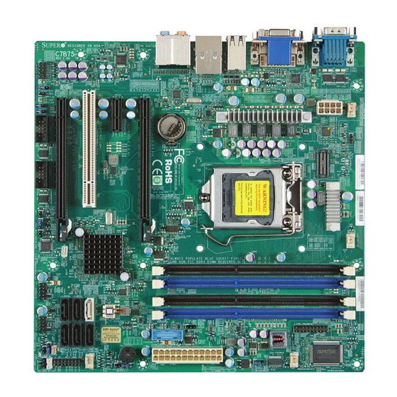
Chapter 1: Introduction Chapter 1 Introduction Overview Checklist Congratulations on purchasing your computer motherboard from an acknowledged leader in the industry. Supermicro boards are designed with the utmost attention to detail to provide you with the highest standards in quality and performance. Please check that the following items have all been included with your motherboard. - Page 14 C7B75 User’s Manual C7B75 Motherboard Image Note: All graphics shown in this manual were based upon the latest PCB Revision available at the time of publishing of the manual. The motherboard you've received may or may not look exactly the same as the graphics shown in this manual.
- Page 15 Chapter 1: Introduction C7B75 Motherboard Layout USB3.0-2/3 USB2.0-2/3 HD AUDIO COM1/2 VGA/DVI USB10-13 JPAC1 JI2C1 JI2C2 C7B75 JPW2 ALWAYS POPULATE BLUE SOCKET FIRST DIMM1A UNB NON-ECC DDR3 DIMM REQUIRED DIMM1B DIMM2A DIMM2B BIOS JTPM1 LICENSE USB3.0, 2.0-0/1 JPW1 JPT1 FAN2...
- Page 16 C7B75 User’s Manual C7B75 Quick Reference SLOT4 USB3.0-2/3 USB2.0-2/3 SLOT5 SLOT7 HD AUDIO COM1/2 VGA/DVI SLOT6 USB10-13 JPAC1 JI2C1 JI2C2 C7B75 JPW2 Socket H2 LGA 1155 35 33 31 36 34 32 ALWAYS POPULATE BLUE SOCKET FIRST DIMM1A DIMM1A UNB NON-ECC DDR3 DIMM REQUIRED...
-
Page 17: Led Indicators
Chapter 1: Introduction C7B75 Jumpers and Connectors Number Name Description Backpanel I/O See "Backpanel I/O Connectors", page 2-13 AUDIO FP Front Panel Audio Header COM4,COM3 Serial Headers for COM4,COM3 System Backup Battery Socket H2, LGA1155 CPU JWOR Wake-On-Ring Header 13,14... -
Page 18: Motherboard Features
C7B75 User’s Manual Motherboard Features Single 2nd & 3rd generation Intel® Core™ i7/i5/i3, Pentium® and Celeron® processors, LGA1155 Socket. Memory Four (4) SDRAM slots support up to 32 GB of DDR3 Unbuf- fered, Non-ECC 1333/1066 memory Supports dual-channel memory bus... - Page 19 Chapter 1: Introduction Video One (1) VGA Port, One (1) DVI Port BIOS 64 Mb AMI BIOS SPI Flash BIOS ® Play and Plug (PnP0, DMI 2.3, PCI 2.3, ACPI 1.0/2.0/3.0, USB Keyboard and SMBIOS 2.5 Power Configuration ACPI/ACPM Power Management Main Switch Override Mechanism Keyboard Wake-up from Soft-Off Internal/External Modem Ring-On...
-
Page 20: System Block Diagram
C7B75 User’s Manual C7B75 Block Diagram SVID VRM 12 PCIe3.0_x16 PCIe x16 SLOT #7 INTEL LGA1155 8.0GT/s Ivy Bridge-DT DDR3 (CHA) DIMM1A (Blue) (Socket-H2) DIMM1B 1600/1333/1066MHz VRD12 DDR3 (CHB) DIMM2A (Blue) DIMM2B 1600/1333/1066MHz x4 DMI x4 FDI 5GT/s 2.7 Gbps... -
Page 21: Chipset Overview
Chapter 1: Introduction Chipset Overview Designed for the needs of the small businesses, the Intel® B75 Express Chipset offers ready solutions for increased PC performance, manageability, and security. Following is a short list of features. For a comprehensive overview of the chipset, please visit Intel's website at http://www.intel.com. -
Page 22: Special Features
Note: To avoid possible system overheating, please be sure to provide adequate airflow to your system. System Resource Alert This feature is available when the system is used with Supero Doctor III in the Windows OS environment or used with Supero Doctor II in Linux. Supero 1-10... -
Page 23: Acpi Features
Chapter 1: Introduction Doctor is used to notify the user of certain system events. For example, you can also configure Supero Doctor to provide you with warnings when the system temperature, CPU temperatures, voltages and fan speeds go beyond predefined thresholds. -
Page 24: Super I/O
C7B75 User’s Manual information, please refer to the web site at http://www.ssiforum.org/). Additionally, in areas where noisy power transmission is present, you may choose to install a line filter to shield the computer from noise. It is recommended that you also install a power surge protector to help avoid problems caused by power surges. -
Page 25: Installation
Chapter 2: Installation Chapter 2 Installation Static-Sensitive Devices Electrostatic-Discharge (ESD) can damage electronic com ponents. To avoid dam- aging your system board, it is important to handle it very carefully. The following measures are generally sufficient to protect your equipment from ESD. Precautions •... -
Page 26: Processor And Heatsink Installation
C7B75 User’s Manual Processor and Heatsink Installation Warning: When handling the processor package, avoid placing direct pressure on the label area of the fan. Important: Always connect the power cable last, and always remove it before adding, removing or changing any hardware components. Make sure that you in- stall the processor into the CPU socket before you install the CPU heatsink. - Page 27 Chapter 2: Installation 2. Gently lift the load lever to open the load plate. Remove the plastic cap. 3. Use your thumb and your index finger to hold the CPU at the North center edge and the South center edge of the CPU. North Center Edge South Center Edge 4.
- Page 28 C7B75 User’s Manual 5. Do not rub the CPU against the surface or against any pins of the socket to avoid damaging the CPU or the socket.) 6. With the CPU inside the socket, inspect the four corners of the CPU to make sure that the CPU is properly installed.
-
Page 29: Installing An Active Cpu Heatsink With Fan
Chapter 2: Installation Installing an Active CPU Heatsink with Fan 1. Locate the CPU Fan power connec- tor on the motherboard. (Refer to the layout on the right for the CPU Fan location.) 2. Position the heatsink so that the heatsink fan wires are closest to the CPU fan power connector and are Thermal Grease... - Page 30 C7B75 User’s Manual 7. Align the four heatsink fasten- ers with the mounting holes on the motherboard. Gently push the pairs of diagonal fasteners (#1 & #2, and #3 & #4) into the mounting holes until you hear a click. Also,...
-
Page 31: Removing The Heatsink
Chapter 2: Installation Removing the Heatsink Warning: We do not recommend that the CPU or the heatsink be removed. However, if you do need to remove the heatsink, please follow the instructions be- low to remove the heatsink and to prevent damage done to the CPU or other components. -
Page 32: Installing Ddr3 Memory
C7B75 User’s Manual Installing DDR3 Memory Note: Check the Supermicro website for recommended memory mod- ules. CAUTION Exercise extreme care when installing or removing DIMM modules to prevent any possible damage. USB3.0-2/3 USB2.0-2/3 DIMM Installation HD AUDIO VGA/DVI COM1/2 USB10-13 JPAC1 1. -
Page 33: Memory Support
Chapter 2: Installation Memory Support The C7B75 Motherboard supports up to 32GB of Unbuffered (UDIMM) non-ECC DDR3 1600/1333/1066 MHz in 4 memory slots. Populating these DIMM modules with a pair of memory modules of the same type and same size will result in interleaved memory, which will improve memory performance. - Page 34 C7B75 User’s Manual Possible System Memory Allocation & Availability System Device Size Physical Memory Remaining (-Available) (4 GB Total System Memory) Firmware Hub flash memory (System BIOS) 1 MB 3.99 Local APIC 4 KB 3.99 Area Reserved for the chipset 2 MB 3.99...
-
Page 35: Motherboard Installation
Philips Screws Only if Needed Location of Mounting Holes USB3.0-2/3 USB2.0-2/3 HD AUDIO COM1/2 VGA/DVI USB10-13 JPAC1 JI2C1 JI2C2 C7B75 JPW2 ALWAYS POPULATE BLUE SOCKET FIRST DIMM1A UNB NON-ECC DDR3 DIMM REQUIRED DIMM1B DIMM2A DIMM2B BIOS JTPM1 LICENSE USB3.0, 2.0-0/1... -
Page 36: Installing The Motherboard
C7B75 User’s Manual Installing the Motherboard 1. Install the I/O shield into the back of the chassis. 2. Locate the mounting holes on the motherboard. (See the previous page.) 3. Locate the matching mounting holes on the chassis. Align the mounting holes on the motherboard against the mounting holes on the chassis. -
Page 37: Connectors/Io Ports
I/O ports. Backplane I/O Panel USB3.0-2/3 USB2.0-2/3 HD AUDIO COM1/2 VGA/DVI USB10-13 JPAC1 JI2C1 JI2C2 C7B75 JPW2 ALWAYS POPULATE BLUE SOCKET FIRST DIMM1A UNB NON-ECC DDR3 DIMM REQUIRED DIMM1B DIMM2A DIMM2B BIOS JTPM1 LICENSE USB3.0, 2.0-0/1... -
Page 38: Universal Serial Bus (Usb)
C7B75 User’s Manual Universal Serial Bus (USB) Six Universal Serial Bus (USB 3.0 ports 2,3) and four (USB 2.0 ports 10,11,12,13) are located on the I/O back panel. USB 2.0 headers 4/5,8/9 and USB 3.0 header 0/1 are used to provide front chassis access using USB cables (not included). See the tables below for pin definitions. -
Page 39: Ethernet Ports
Chapter 2: Installation Ethernet Ports LAN Ports Pin Definition There is one Gigabit Ethernet port Pin# Definition (LAN1) located next to the HD Audio P2V5SB SGND Connectors on the I/O Backpanel to TD0+ Act LED provide a network connection. This TD0- P3V3SB port accepts RJ45 type cables. -
Page 40: Front Accessible Audio Header
C7B75 User’s Manual Front Accessible Audio Header 10-in Audio Pin Definitions A 10-pin Audio header is also Pin# Signal located on the motherboard. This Microphone_Left header allows you to use the on- Audio_Ground board sound for audio playback. Microphone_Right Connect an audio cable to the au- Audio_Detect dio header to use this feature. -
Page 41: Dvi Port (Dvi)
Chapter 2: Installation DVI Port (DVI) One DVI Port (Digital Visual Interface) is located next to the VGA port on the I/O backpanel. This connector is used to display both high definition video and digital sound through an HDMI-capable display, using a single HDMI cable (not included). -
Page 42: Front Control Panel
C7B75 User’s Manual Front Control Panel JF1 contains header pins for various buttons and indicators that are normally located on a control panel at the front of the chassis. These connectors are designed spe- cifically for use with Supermicro chassis. See the figure below for the descriptions of the front control panel buttons and LED indicators. -
Page 43: Front Control Panel Pin Definitions
Chapter 2: Installation Front Control Panel Pin Definitions Power LED Power LED Pin Definitions (JF1) The Power LED connection is located Pin# Definition on pins 15 and 16 of JF1. Refer to the table on the right for pin definitions. Ground HDD LED The HDD LED connection is located... -
Page 44: Nic1 (Lan1)
C7B75 User’s Manual NIC1 (LAN1) LAN1/LAN2 LED Pin Definitions (JF1) The NIC (Network Interface Controller) Pin# Definition LED connection for LAN port 1 is located 9/11 on pins 11 and 12 of JF1. NIC1 LED is a 10/12 Ground 2-pin NIC LED header. Attach NIC LED cables to NIC1 LED indicators to display network activity. -
Page 45: Reset Button
Chapter 2: Installation Reset Button The Reset Button connection is located Reset Button Pin Definitions (JF1) on pins 3 and 4 of JF1. Attach it to a Pin# Definition hardware reset switch on the computer Reset case to reset the system. Refer to the Ground table on the right for pin definitions. -
Page 46: Connecting Cables
C7B75 User’s Manual Connecting Cables This section provides brief descriptions and pin-out definitions for onboard headers and connectors. Be sure to use the correct cable for each header or connector. ATX Power 24-pin Connector ATX Main PWR & CPU PWR Pin Definitions (JPW1) Connectors (JPW1 &... -
Page 47: Fan Headers (Fan 1 ~ Fan 4)
Chapter 2: Installation Fan Headers (Fan 1 ~ Fan 4) Fan Header Pin Definitions The C7B75 has four fan headers (Fan 1~Fan 4). Pin# Definition These fans are 4-pin fan headers. Although pins Ground (Black) 1-3 of the fan headers are backward compatible 2.5A/+12V... -
Page 48: Internal Buzzer (Sp1)
C7B75 User’s Manual Internal Buzzer (SP1) Internal Buzzer Pin Definition The Internal Buzzer (SP1) can be Pin# Definitions used to provide audible indications for Pin 1 Pos. (+) Beep In various beep codes. See the table on Pin 2 Neg. (-) Alarm the right for pin definitions. -
Page 49: Onboard Power Led (Jled)
Ground A. PWR LED B. COM3 C. COM4 USB3.0-2/3 USB2.0-2/3 HD AUDIO COM1/2 VGA/DVI USB10-13 JPAC1 JI2C1 JI2C2 C7B75 JPW2 ALWAYS POPULATE BLUE SOCKET FIRST DIMM1A UNB NON-ECC DDR3 DIMM REQUIRED DIMM1B DIMM2A DIMM2B BIOS JTPM1 LICENSE USB3.0, 2.0-0/1 JPW1... -
Page 50: Dom Pwr Connector (Jsd1)
C7B75 User’s Manual DOM PWR Connector (JSD1) DOM PWR Pin Definitions The Disk-On-Module (DOM) power Pin# Definition connector, located at JSD1, provides 5V (Gen1/Gen) power to a solid state Ground DOM storage device connected to one Ground of the SATA ports. See the table on the right for pin definitions. -
Page 51: Wake-On-Ring (Jwor)
See the table on the right for pin defi- nitions. B. Power LED Header USB3.0-2/3 USB2.0-2/3 HD AUDIO COM1/2 VGA/DVI USB10-13 JPAC1 JI2C1 JI2C2 C7B75 JPW2 ALWAYS POPULATE BLUE SOCKET FIRST DIMM1A UNB NON-ECC DDR3 DIMM REQUIRED DIMM1B DIMM2A DIMM2B BIOS JTPM1 LICENSE USB3.0, 2.0-0/1... -
Page 52: Tpm Header (Jtpm1)
C7B75 User’s Manual TPM Header (JTPM1) Trusted Platform Module Header Pin Definitions This header is used to connect a Pin # Definition Pin # Definition Trusted Platform Module (TPM), which LCLK is available from a third-party vendor. LFRAME No Pin... -
Page 53: Jumper Settings
This will erase all user settings and revert everything to their factory-set defaults. USB3.0-2/3 USB2.0-2/3 A. Clear CMOS HD AUDIO COM1/2 VGA/DVI USB10-13 JPAC1 JI2C1 JI2C2 C7B75 JPW2 ALWAYS POPULATE BLUE SOCKET FIRST DIMM1A UNB NON-ECC DDR3 DIMM REQUIRED DIMM1B DIMM2A DIMM2B BIOS JTPM1 LICENSE USB3.0, 2.0-0/1... -
Page 54: Pci Slot Smb Enable (Ji2C1/Ji2C2)
C7B75 User’s Manual PCI Slot SMB Enable (JI2C1/JI2C2) PCI Slot_SMB Enable Jumper Settings Use Jumpers JI2C1/JI2C2to enable PCI Jumper Setting Definition SMB (System Management Bus) support Short Enabled to improve system management for the Open (Default) Disabled PCI slots. See the table on the right for jumper settings. -
Page 55: Manufacturing Mode (Jpme2)
Pins 2-3 Disabled A. Manufacturing Mode B. Audio Enable USB3.0-2/3 USB2.0-2/3 HD AUDIO COM1/2 VGA/DVI USB10-13 JPAC1 JI2C1 JI2C2 C7B75 JPW2 ALWAYS POPULATE BLUE SOCKET FIRST DIMM1A UNB NON-ECC DDR3 DIMM REQUIRED DIMM1B DIMM2A DIMM2B BIOS JTPM1 LICENSE USB3.0, 2.0-0/1 JPW1... -
Page 56: Tpm Support Enable (Jpt1)
C7B75 User’s Manual TPM Support Enable (JPT1) TPM Support Enable Jumper Settings JPT1 allows the user to enable TPM Jumper Setting Definition (Trusted Platform Module) support to 1-2 (Default) Enabled improve data integrity and system secu- Disabled rity. See the table on the right for jumper settings. -
Page 57: Onboard Indicators
LED location. A. LAN Port 1 B. PWR LED USB3.0-2/3 USB2.0-2/3 HD AUDIO COM1/2 VGA/DVI USB10-13 JPAC1 JI2C1 JI2C2 C7B75 JPW2 ALWAYS POPULATE BLUE SOCKET FIRST DIMM1A UNB NON-ECC DDR3 DIMM REQUIRED DIMM1B DIMM2A DIMM2B BIOS JTPM1 LICENSE USB3.0, 2.0-0/1... -
Page 58: Sata Connections
SATA_RXP board. These SATA ports are supported Ground by the Intel B75 Express Chipset and provide faster data transmission than C7B75 SATA Connector Types legacy Parallel ATA. See the table on Port# Connection Type the right for pin definitions. I-SATA 0 SATA 3.0... -
Page 59: Troubleshooting
Chapter 3: Troubleshooting Chapter 3 Troubleshooting Troubleshooting Procedures Use the following procedures to troubleshoot your system. If you have followed all of the procedures below and still need assistance, refer to the ‘Technical Support Procedures’ and/or ‘Returning Merchandise for Service’ section(s) in this chapter. Always disconnect the AC power cable before adding, changing or installing any hardware components. -
Page 60: No Video
C7B75 User’s Manual No Video 1. If the power is on, but you have no video--in this case, you will need to re- move all the add-on cards and cables first. 2. Use the speaker to determine if any beep codes exist. (Refer to Appendix A for details on beep codes.) -
Page 61: Frequently Asked Questions
Frequently Asked Questions Question: What type of memory does my motherboard support? Answer: The C7B75 supports up to 32GB of unbuffered Non-ECC DDR3 SDRAM (1.5V, 1333/1066 MHz). See Section 2-3 for details on installing memory. Question: How do I update my BIOS? Answer: We do NOT recommend that you upgrade your BIOS if you are not experiencing any problems with your system. - Page 62 Note: Always use the file named “ami.bat” to update the BIOS, and insert a space between "ami.bat" and the filename. The BIOS-ROM-filename will bear the motherboard name (i.e., C7B75) and build version as the extension. For example, "C7B750.115".When completed, your system will automatically reboot.
-
Page 63: Battery Removal And Installation
USB floppy drive instead of the onboard floppy drive. For the IPMI jumper location, please check Chapter 1. Question: What is the heatsink part number for my C7B75 motherboard? Answer: For the 1U passive heatsink, ask for SNK-P0046P (back plate is included). -
Page 64: Returning Merchandise For Service
C7B75 User’s Manual Battery Installation 1. To install an onboard battery, follow the steps 1& 2 above and continue below: 2. Identify the battery's polarity. The positive (+) side should be facing up. 3. Insert the battery into the battery holder and push it down until you hear a click to ensure that the battery is securely locked. -
Page 65: Introduction
BIOS Introduction This chapter describes the AMI BIOS Setup Utility for the C7B75. The ROM BIOS is stored in a Flash EEPROM and can be easily updated. This chapter describes the basic navigation of the AMI BIOS Setup Utility setup screens. -
Page 66: How To Start The Setup Utility
C7B75 User’s Manual How to Start the Setup Utility Normally, the only visible Power-On Self-Test (POST) routine is the memory test. As the memory is being tested, press the <Delete> key to enter the main menu of the AMI BIOS Setup Utility. From the main menu, you can access the other setup screens. -
Page 67: System Overview: The Following Bios Information Will Be Displayed
Day MM/DD/YY format. The time is entered in HH:MM:SS format. Note: The time is in the 24-hour format. For example, 5:30 P.M. appears as 17:30:00. The following BIOS items will also be displayed: Supermicro C7B75 Version Build Date Processor... -
Page 68: Advanced Setup Configurations
C7B75 User’s Manual Advanced Setup Configurations Use the arrow keys to select Boot Setup and press <Enter> to access the submenu items: Ap o Setup U lity - Copyright (C) 2011 American Megatrends, Inc. Main Advanced Boot Security Save & Exit... -
Page 69: Interrupt 19 Capture
Chapter 4: AMI BIOS Interrupt 19 Capture Interrupt 19 is the software interrupt that handles the boot disk function. When this item is set to Enabled, the ROM BIOS of the host adaptors will "capture" Interrupt 19 at bootup and allow the drives that are attached to these host adaptors to function as bootable disks. -
Page 70: Active Processor Cores
C7B75 User’s Manual CPU Information This submenu displays information regarding the installed CPU. Active Processor Cores Enables selection of the number of the processor's core to activate. (Please refer to Intel's web site for more information.) The options are All, 1, 2, and 3. -
Page 71: Cpu Ppm Configuration
Chapter 4: AMI BIOS If Enabled, the BIOS will monitor the level of Electromagnetic Interference caused by the components and will attempt to decrease the interference whenever needed. The options are Enabled and Disabled. CPU PPM Configuration Use this feature to select a power-saving scheme for the motherboard. The options are Disabled, Energy Efficient and Custom. -
Page 72: Chipset Configuration
C7B75 User’s Manual Chipset Configuration WARNING: Setting the wrong values in the following sections may cause the system to malfunction. System Agent (SA) Configuration Use this section to modify System Agent (SA) parameters. Graphics Configuration Internal Graphics Use this item to keep IGD (Internal Graphics Device) enabled based on the setup options. -
Page 73: Nb Pcie Configuration
Chapter 4: AMI BIOS Graphics Performance Analyzers Use this feature to enable or disable the Intel graphics performance analyzers counters. The options are Enabled and Disabled. NB PCIe Configuration PEG0 - Gen X Use this item to configure the desired Generation support for PEG0. The options are Auto, Gen1, Gen2, and Gen3. -
Page 74: South Bridge Configuration
C7B75 User’s Manual Scrambler Seed Generation Off Use this item to control memory scrambler seed generation. Select Enabled to prevent generating scrambler seed. Select Disabled to always generate scram- bler seed. The options are Enabled and Disabled. Memory Remap Select Enabled to enable memory remap above 4G. The options are Enabled and Disabled. -
Page 75: Sata Configuration
Chapter 4: AMI BIOS Port 60/64 Emulation This feature enables or disables I/O port 60h/64h emulation support. This should be enabled for complete USB keyboard legacy support for non-USB-aware Op- erating Systems. The options are Disabled and Enabled. BIOS EHCI Hand-Off This item is for Operating Systems that do not support Enhanced Host Control- ler Interface (EHCI) hand-off. -
Page 76: Pcie/Pci/Pnp Configuration
C7B75 User’s Manual IDE Mode The following items are displayed when IDE Mode is selected: IDE Legacy / Native Mode Selection Use this item to select Native Mode or IDE Legacy support. The options are Native and Legacy. PCIe/PCI/PnP Configuration ... -
Page 77: Slot4 Pci-E 2.0 X4 (In X16 ) Oprom
Chapter 4: AMI BIOS SLOT4 PCI-E 2.0 x4 (in x16 ) OPROM Select Enabled to enable Option ROM support to boot the computer using a de- vice installed on the slot specified above. The options are Enabled and Disabled. SLOT5 PCI 33MHz OPROM Select Enabled to enable Option ROM support to boot the computer using a de- vice installed on the slot specified above. -
Page 78: Serial Port 1 Settings
C7B75 User’s Manual Serial Port 1 Settings This option specifies the base I/O port address and the Interrupt Request address of Serial Port 1. Select Disabled to prevent the serial port from accessing any system resources. When this option is set to Disabled, the serial port becomes unavailable. -
Page 79: Cpu Temperature Display Mode
Chapter 4: AMI BIOS needs between system cooling and power saving. This setting is recommended for regular systems with normal hardware configurations. The options are Full Speed (@100% of PWM Cycle), and Standard (@50% of PWM Cycle). CPU Temperature Display Mode This feature displays the CPU temperature detected by DTS (i.e., +34 C) or tem- perature status in text ("Low", "Medium"... -
Page 80: Acpi Settings
C7B75 User’s Manual ACPI Settings Use this feature to configure Advanced Configuration and Power Interface (ACPI) power management settings for your system. High Precision Event Timer Select Enabled to activate the High Performance Event Timer (HPET) that produces periodic interrupts at a much higher frequency than a Real-time Clock (RTC) does in... - Page 81 Chapter 4: AMI BIOS TPM Enable Status This item displays the status of TPM Support to indicate if TPM is currently enabled or disabled. TPM Active Status This item displays the status of TPM Support to indicate if TPM is currently ac- tive or deactivated.
-
Page 82: Pch-Fw Configuration
C7B75 User’s Manual PCH-FW Configuration This feature displays ME configuration settings. Me Firmware Re-Flash Use this feature to enable re-flashing of the ME firmware. The options are Disabled and Enabled. Intel® Ethernet Controller 10 Gigabit This item displays the following information on the Intel 82579V Gigabit Network Connection. -
Page 83: Boot Settings
Chapter 4: AMI BIOS Boot Settings Ap o Setup U lity - Copyright (C) 2011 American Megatrends, Inc. Main Advanced Boot Security Save & Exit Boot Op ons Priority 07.69 Set Boot Priority. Boot Op on #1 [CD/DVD] Boot Op on #2 [Hard Disk:P5: WDC WD8...] Boot Op on #3 [USB Hard Disk]... -
Page 84: Security Settings
C7B75 User’s Manual Security Settings Ap o Setup U lity - Copyright (C) 2011 American Megatrends, Inc. Save & Exit Main Advanced Boot Security Setup: Check password Password Descrip on while invoking setup. Always: Check password If ONLY the administrator’s password is set,... -
Page 85: Save And Exit Options
Chapter 4: AMI BIOS Save and Exit Options Select the Exit tab from the BIOS Setup Utility screen to enter the Exit BIOS Setup screen. Ap o Setup U lity - Copyright (C) 2011 American Megatrends, Inc. Main Advanced Boot Security Save &... -
Page 86: Restore Optimized Defaults
C7B75 User’s Manual Restore Optimized Defaults To set this feature, select Restore Optimized Defaults from the Exit menu and press <Enter>. These are factory settings designed for maximum system stability, but not for maximum performance. Save as User Defaults To set this feature, select Save as User Defaults from the Exit menu and press <Enter>. -
Page 87: A-1 Bios Error Beep Codes
Appendix A: POST Error Beep Codes Appendix A BIOS Error Beep Codes During the POST (Power-On Self-Test) routines, which are performed each time the system is powered on, errors may occur. Non-fatal errors are those which, in most cases, allow the system to continue with bootup. - Page 88 C7B75 User’s Manual Notes...
-
Page 89: Software Installation Instructions
Appendix B: Software Installation Instructions Appendix B Software Installation Instructions B-1 Installing Drivers After you've installed the Windows Operating System, a screen as shown below will appear. You are ready to install software programs and drivers that have not yet been installed. To install these software programs and drivers, click the icons to the right of these items. -
Page 90: Configuring Superdoctor ® Iii
C7B75 User’s Manual B-2 Configuring SuperDoctor ® The SuperDoctor III program is a Web-based management tool that supports remote management capability. It includes Remote and Local Management tools. The local management tool is called the SD III Client. The SuperDoctor III program included on the CDROM that came with your motherboard allows you to monitor the envi- ronment and operations of your system. - Page 91 Appendix B: Software Installation Instructions SuperDoctor III Interface Display Screen-II (Remote Control) Note: The SuperDoctor III software and manual may be downloaded from our Website at: http://www.supermicro.com/products/accessories/software/SuperDoctorIII.cfm. For Linux, we still recommend that you use SuperDoctor II, this version is also available for download at the link above.
- Page 92 C7B75 User’s Manual Notes...
-
Page 93: Uefi Bios Recovery Instructions
Appendix C: UEFI BIOS Recovery Appendix C UEFI BIOS Recovery Instructions Warning! Do not upgrade the BIOS unless your system has a BIOS-related issue. Flashing the wrong BIOS can cause irreparable damage to the system. In no event shall Supermicro be liable for direct, indirect, special, incidental, or consequential damages arising from a BIOS update. - Page 94 C7B75 User’s Manual a USB CD/DVD ROM/RW device can be used for this purpose. However, a USB Hard Disk drive cannot be used for BIOS recovery at this time. To perform UEFI BIOS recovery using a USB-attached device, follow the instruc- tions below.
- Page 95 Appendix C: UEFI BIOS Recovery 5. When the screen as shown above displays, using the arrow key, select the item- "Proceed with flash update" and press the <Enter> key. You will see the progress of BIOS Recovery as shown in the screen below. Note: Do not interrupt the process of BIOS flashing until it is com- pleted.
- Page 96 C7B75 User’s Manual 8. When a DOS prompt appears, enter AMI.BAT BIOSname.### at the prompt. Note: Do not interrupt this process until BIOS flashing is completed. 9. After seeing the message that BIOS update is completed, unplug the AC pow- er cable from the power supply to clear CMOS, and then plug the AC power cable in the power supply again to power on the system.
- Page 97 (Disclaimer Continued) The products sold by Supermicro are not intended for and will not be used in life support systems, medical equipment, nuclear facilities or systems, aircraft, aircraft devices, aircraft/emergency communication devices or other critical systems whose failure to perform be reasonably expected to result in significant injury or loss of life or catastrophic property damage.
Need help?
Do you have a question about the C7B75 and is the answer not in the manual?
Questions and answers