Table of Contents
Advertisement
Quick Links
Advertisement
Table of Contents

Related Manuals for Supero C7H61


Summary of Contents for Supero C7H61
- Page 1 C7H61 C7H61-L USER’S MANUAL Revision 1.1...
- Page 2 The information in this User’s Manual has been carefully reviewed and is believed to be accurate. The vendor assumes no responsibility for any inaccuracies that may be contained in this document, makes no commitment to update or to keep current the information in this manual, or to notify any person or organization of the updates.
-
Page 3: About This Motherboard
C7H61 supports a single 2nd and 3rd generation Intel® Core™ i7/i5/ i3, Pentium, Celeron desktop processor in an LGA 1155 socket. With the Intel® H61 Express chipset built in, the C7H61 motherboard offers excellent balance of price/ performance for entry level or embedded applications. Please refer to our website (http://www.supermicro.com/products/) for processor and memory support updates. -
Page 4: Conventions Used In The Manual
C7H61 User’s Manual Conventions Used in the Manual: Special attention should be given to the following symbols for proper installation and to prevent damage done to the components or injury to yourself: Danger/Caution: Instructions to be strictly followed to prevent catastrophic sys- tem failure or to avoid bodily injury Warning: Critical information to prevent damage to the components or data loss. -
Page 5: Contacting Supermicro
Contacting Supermicro Contacting Supermicro Headquarters Address: Super Micro Computer, Inc. 980 Rock Ave. San Jose, CA 95131 U.S.A. Tel: +1 (408) 503-8000 Fax: +1 (408) 503-8008 Email: marketing@supermicro.com (General Information) support@supermicro.com (Technical Support) Website: www.supermicro.com Europe Address: Super Micro Computer B.V. Het Sterrenbeeld 28, 5215 ML 's-Hertogenbosch, The Netherlands Tel:... -
Page 6: Table Of Contents
C7H61 User’s Manual Table of Contents Preface About This Motherboard ....................iii Manual Organization ..................... iii Conventions Used in the Manual: .................iv Contacting Supermicro ....................v Chapter 1 Introduction Overview ......................1-1 Checklist ......................1-1 Motherboard Features ..................1-7 Chipset Overview ..................1-10 Intel ®... - Page 7 Table of Contents Location of Mounting Holes ................2-10 Installing the Motherboard ................2-11 Connectors/IO Ports ..................2-12 Backplane I/O Panel ..................2-12 ATX PS/2 Keyboard/Mouse Ports ............2-13 Universal Serial Bus (USB) ..............2-14 Ethernet Ports ..................2-15 Back Panel High Definition Audio (HD Audio) ........2-15 HDMI Port ....................
- Page 8 How to Start the Setup Utility ................. 4-2 Main Setup ...................... 4-2 System Overview: The following BIOS information will be displayed: ..4-3 System Time/System Date ................ 4-3 Supermicro C7H61 ..................4-3 BIOS Version ....................4-3 ME Firmware Version ................. 4-3 Build Date ....................4-3 Processor ....................
- Page 9 Table of Contents Physical Count ................... 4-3 Logical Count ..................... 4-3 System Memory ..................4-3 Size......................4-3 4-3 Advanced Setup Configurations..............4-4 Boot Feature ....................4-4 Quiet Boot ....................4-4 AddOn ROM Display Mode ................ 4-4 Bootup Num-Lock ..................4-4 Wait For 'F1' If Error ................... 4-4 Interrupt 19 Capture ...................
- Page 10 C7H61 User’s Manual SATA Mode ....................4-12 PCIe/PCI/PnP Configuration ..............4-13 PCI ROM Priority ..................4-13 PCI Latency Timer ..................4-13 Active State Power Management ............. 4-13 PCIe Max Read Request Size ..............4-13 PCI Slot 1, 2, 3, 4, 5 Option ROM ............4-13 PCIe Slot 6 &...
- Page 11 Table of Contents VCORE, 12V, VDIMM, 5VCC, VTT_CPU, AVCC, 3.3VCC, VSB, VBAT . 4-19 ACPI Configuration ..................4-20 High Precision Event Timers ..............4-20 Suspend Mode ..................4-20 Trusted Computing ..................4-20 Trusted Computing Configuration ............4-20 Security Settings ................... 4-21 Administrator Password ................4-21 User Password: ..................
- Page 12 C7H61 User’s Manual Notes...
-
Page 13: Chapter 1 Introduction
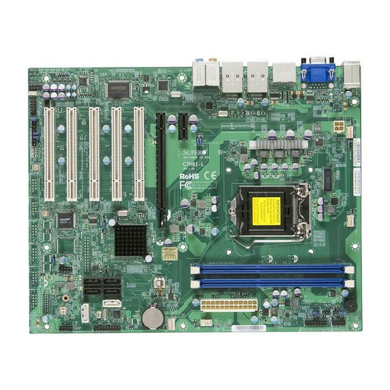
Chapter 1: Introduction Chapter 1 Introduction Overview Checklist Congratulations on purchasing your computer motherboard from an acknowledged leader in the industry. Supermicro boards are designed with the utmost attention to detail to provide you with the highest standards in quality and performance. Please check that the following items have all been included with your motherboard. - Page 14 C7H61 User’s Manual C7H61 Motherboard Image Note: All graphics shown in this manual were based upon the latest PCB Revision available at the time of publishing of the manual. The motherboard you've received may or may not look exactly the same as the graphics shown in this manual.
- Page 15 Chapter 1: Introduction C7H61-L Motherboard Image Note: All graphics shown in this manual were based upon the latest PCB Revision available at the time of publishing of the manual. The motherboard you've received may or may not look exactly the same as the graphics shown in this manual.
- Page 16 NIC2 NIC1 USB10/11 JTPM1:TPM/PORT80 LED+ LED- supported on the C7H61 only Important Notes to the User • See Chapter 2 for detailed information on jumpers, I/O ports and JF1 front panel connections. • " " indicates the location of "Pin 1".
- Page 17 Name Description Default JPAC1 Audio Enable Pins 1-2 (Enabled) 8,10 JI2C3,JI2C4 SMB Header for PCI Slots C7H61-L: Short (Enabled), C7H61: Open (Disabled) JBT1 CMOS Reset Open (Disabled) JPUSB1 USB Wake-Up Pins 2-3 (Disabled) JWD1 Watch Dog Timer Reset Pins 1-2 (Reset)
-
Page 18: Led Indicators
S/PDIF OUT, S/PDIF IN S/PDIF OUT/IN Digital Audio Headers Chassis Intrusion Header JWOR Wake-On-Ring Header USB 3.0 1/0 USB Header 1/0 (3.0) (supported on the C7H61 only) 16,45 USB10/11,8/9 USB 2.0 Header 10/11,8/9 17,20 A-SATA 0,1 (ASMedia) SATA 3.0 Ports (up to 6Gb/s) -
Page 19: Motherboard Features
Six (6) USB 2.0 ports on the rear I/O panel All models: Four (4) Front Accessible USB 2.0 ports on two headers C7H61 only: Two (2) Front Accessible USB 3.0 ports on one header Keyboard/Mouse One shared PS/2 Keyboard/Mouse port on the I/O... - Page 20 C7H61 User’s Manual Super I/O Nuvoton NCT6776F BIOS 64 Mb AMI BIOS SPI Flash BIOS ® Plug and Play (PnP), PCI 3.0, ACPI 4.0, USB Keyboard and SMBIOS 2.7 Power Configuration ACPI/ACPM Power Management Main Switch Override Mechanism Keyboard Wake-up from Soft-Off...
- Page 21 Chapter 1: Introduction C7H61 Block Diagram System Block Diagram Note: This is a general block diagram and may not exactly represent the features on your motherboard. See the Motherboard Features pages for the actual specifications of each motherboard.
-
Page 22: Chipset Overview
The Intel® H61 Express Chipset is an entry-level product designed to deliver the most critical features at the best possible price point. Based on the capabilities of this chipset, the C7H61 motherboard utilizes the chipset's design to deliver a cost-effective price point without sacrificing the needed performance for an entry- level or embedded platform. -
Page 23: Special Features
Chapter 1: Introduction Special Features Recovery from AC Power Loss Basic I/O System (BIOS) provides a setting for you to determine how the system will respond when AC power is lost and then restored to the system. You can choose for the system to remain powered off, (in which case you must press the power switch to turn it back on), or for it to automatically return to a power-on state. -
Page 24: Acpi Features
C7H61 User’s Manual is used to notify the user of certain system events. For example, you can also configure SuperDoctor to provide you with warnings when the system temperature, CPU temperatures, voltages and fan speeds go beyond predefined thresholds. ACPI Features ACPI stands for Advanced Configuration and Power Interface. -
Page 25: Super I/O
Chapter 1: Introduction It is strongly recommended that you use a high quality power supply that meets ATX power supply Specification 2.02 or above. It must also be SSI compliant. (For more information, please refer to the web site at http://www.ssiforum.org/). Additionally, in areas where noisy power transmission is present, you may choose to install a line filter to shield the computer from noise. - Page 26 C7H61 User’s Manual Notes 1-14...
-
Page 27: Chapter 2 Installation
Chapter 2: Installation Chapter 2 Installation Static-Sensitive Devices Electrostatic-Discharge (ESD) can damage electronic com ponents. To avoid dam- aging your system board, it is important to handle it very carefully. The following measures are generally sufficient to protect your equipment from ESD. Precautions •... -
Page 28: Processor And Heatsink Installation
C7H61 User’s Manual Processor and Heatsink Installation Warning: When handling the processor package, avoid placing direct pressure on the label area of the fan. Important: Always connect the power cable last, and always remove it before adding, removing or changing any hardware components. Make sure that you in- stall the processor into the CPU socket before you install the CPU heatsink. - Page 29 Chapter 2: Installation 2. Gently lift the load lever to open the load plate. Remove the plastic cap. 3. Use your thumb and your index finger to hold the CPU at the North center edge and the South center edge of the CPU. North Center Edge South Center Edge 4.
- Page 30 C7H61 User’s Manual 5. Do not rub the CPU against the surface or against any pins of the socket to avoid damaging the CPU or the socket.) 6. With the CPU inside the socket, inspect the four corners of the CPU to make sure that the CPU is properly installed.
-
Page 31: Installing An Active Cpu Heatsink With Fan
Chapter 2: Installation Installing an Active CPU Heatsink with Fan 1. Locate the CPU Fan power connec- tor on the motherboard. (Refer to the layout on the right for the CPU Fan location.) 2. Position the heatsink so that the heatsink fan wires are closest to the CPU fan power connector and are Thermal Grease... - Page 32 C7H61 User’s Manual 7. Align the four heatsink fasten- ers with the mounting holes on the motherboard. Gently push the pairs of diagonal fasteners (#1 & #2, and #3 & #4) into the mounting holes until you hear a click. Also,...
-
Page 33: Removing The Heatsink
Chapter 2: Installation Removing the Heatsink Warning: We do not recommend that the CPU or the heatsink be removed. However, if you do need to remove the heatsink, please follow the instructions be- low to remove the heatsink and to prevent damage done to the CPU or other components. -
Page 34: Installing Ddr3 Memory
C7H61 User’s Manual Installing DDR3 Memory Note: Check the Supermicro website for recommended memory mod- ules. CAUTION Exercise extreme care when installing or removing DIMM modules to prevent any possible damage. DIMM Installation HD AUDIO AUDIO FP JWOL1 JWOL:WAKE ON LAN... -
Page 35: Memory Support
Chapter 2: Installation Memory Support The C7H61 motherboard series supports up to 16GB of Unbuffered (UDIMM) non-ECC DDR3 1600/1333/1066 MHz in 2 memory slots. Towards the CPU DIMMA1 DIMMB1 Towards the edge of the motherboard Memory Population Guidelines When installing memory modules, the DIMM slots should be populated in the following order: DIMMA1 and DIMMB1. -
Page 36: Motherboard Installation
C7H61 User’s Manual Motherboard Installation All motherboards have standard mounting holes to fit different types of chassis. Make sure that the locations of all the mounting holes for both motherboard and chassis match. Although a chassis may have both plastic and metal mounting fas- teners, metal ones are highly recommended because they ground the motherboard to the chassis. -
Page 37: Installing The Motherboard
Chapter 2: Installation Installing the Motherboard 1. Install the I/O shield into the back of the chassis. 2. Locate the mounting holes on the motherboard. (See the previous page.) 3. Locate the matching mounting holes on the chassis. Align the mounting holes on the motherboard against the mounting holes on the chassis. -
Page 38: Connectors/Io Ports
I. USB 2 (2.0) O. Surround Out C. USB 1 (2.0) J. USB 3 (2.0) P. S/PDIF Out (Optical) Audio D. COM 1 (C7H61 Only) K. LAN2 Port Q. Line In E. VGA Port L. USB 4 (2.0) R. Line Out F. -
Page 39: Atx Ps/2 Keyboard/Mouse Ports
Chapter 2: Installation ATX PS/2 Keyboard/Mouse PS/2 Keyboard/Mouse Pin Ports Definitions PS2 Keyboard PS2 Mouse The ATX PS/2 keyboard and Pin# Definition Pin# Definition PS/2 mouse are located next to KB Data Mouse Data the Back Panel USB Ports 8/9 on No Connection No Connection the motherboard. -
Page 40: Universal Serial Bus (Usb)
C7H61 User’s Manual Universal Serial Bus (USB) Six Universal Serial Bus 2.0 ports (0~5) are located on the I/O back panel. USB 2.0 headers 8/9,10/11 and USB 3.0 header 0/1* are used to provide front chassis access using USB cables (not included). See the tables below for pin definitions. -
Page 41: Ethernet Ports
Chapter 2: Installation Ethernet Ports LAN Ports Pin Definition Two Gigabit Ethernet ports (LAN1/ Pin# Definition LAN2) are located next to the HD Au- P2V5SB SGND dio Connector on the I/O Backpanel to TD0+ Act LED provide network connections. These TD0- P3V3SB ports accept RJ45 type cables. -
Page 42: Hdmi Port
DisplayPort Task Group. DisplayPort Connects to virtually any device, and an Active DisplayPort adaptor allows legacy devices with VGA, DVI and HDMI ports to be connected easily. C7H61 supports DisplayPort standard version 1.1a. Serial Port (COM1) Serial Port COM1... -
Page 43: Front Control Panel
Chapter 2: Installation Front Control Panel JF1 contains header pins for various buttons and indicators that are normally located on a control panel at the front of the chassis. These connectors are designed spe- cifically for use with Supermicro chassis. See the figure below for the descriptions of the front control panel buttons and LED indicators. -
Page 44: Front Control Panel Pin Definitions
C7H61 User’s Manual Front Control Panel Pin Definitions Power LED Power LED Pin Definitions (JF1) The Power LED connection is located Pin# Definition on pins 15 and 16 of JF1. Refer to the table on the right for pin definitions. -
Page 45: Nic1/Nic2 (Lan1/Lan2)
Chapter 2: Installation NIC1/NIC2 (LAN1/LAN2) LAN1/LAN2 LED Pin Definitions (JF1) The NIC (Network Interface Controller) Pin# Definition LED connection for LAN port 1 is located 9/11 on pins 11 and 12 of JF1, and the LED 10/12 Ground connection for LAN Port 2 is on Pins 9 and 10. -
Page 46: Reset Button
C7H61 User’s Manual Reset Button The Reset Button connection is located Reset Button Pin Definitions (JF1) on pins 3 and 4 of JF1. Attach it to a Pin# Definition hardware reset switch on the computer Reset case to reset the system. Refer to the Ground table on the right for pin definitions. -
Page 47: Connecting Cables
Chapter 2: Installation Connecting Cables This section provides brief descriptions and pin-out definitions for onboard headers and connectors. Be sure to use the correct cable for each header or connector. For information on Backpanel USB and Front Panel USB ports, refer to Page 2-14. For Front Panel pin defintions, please refer to Page 2-17. -
Page 48: Fan Headers (Fan 1 ~ Fan 4)
C7H61 User’s Manual Fan Headers (Fan 1 ~ Fan 4) Fan Header Pin Definitions The C7H61 has four fan headers (Fan 1~Fan 4). Pin# Definition These fans are 4-pin fan headers. Although pins Ground (Black) 1-3 of the fan headers are backward compatible 2.5A/+12V... -
Page 49: Internal Buzzer (Sp1)
Chapter 2: Installation Internal Buzzer (SP1) Internal Buzzer Pin Definition The Internal Buzzer (SP1) can be Pin# Definitions used to provide audible indications for Pin 1 Pos. (+) Beep In various beep codes. See the table on Pin 2 Neg. (-) Alarm the right for pin definitions. -
Page 50: Serial Ports (Com2 ~ Com8)
C7H61 User’s Manual Serial Ports (COM2 ~ COM8) Serial Ports COM2, COM5~COM8 Pin Definitions In addition to COM1, which is located Pin # Definition Pin # Definition on the I/O back panel, there are seven (7) serial port headers on the mother- board for COM2~COM8. -
Page 51: Dom Pwr Connector (Jsd1)
Chapter 2: Installation DOM PWR Connector (JSD1) DOM PWR Pin Definitions The Disk-On-Module (DOM) power Pin# Definition connector, located at JSD1, provides 5V (Gen1/Gen) power to a solid state Ground DOM storage device connected to one Ground of the SATA ports. See the table on the right for pin definitions. -
Page 52: Wake-On-Ring (Jwor)
C7H61 User’s Manual Wake-On-Ring (JWOR) Wake-On-Ring Pin Definitions The Wake-On-Ring header is located Pin# Definition at JWOR. This function allows your Ground computer to wake up when receiving Wake-up an incoming call to the modem while in the suspend state. This header is provided to support legacy devices. -
Page 53: Tpm Header (Jtpm1)
Chapter 2: Installation TPM Header (JTPM1) Trusted Platform Module Header Pin Definitions This header is used to connect a Pin # Definition Pin # Definition Trusted Platform Module (TPM), which LCLK is available from a third-party vendor. LFRAME No Pin A TPM is a security device that sup- LRESET VCC5... -
Page 54: Lpt1 Header (Printer)
C7H61 User’s Manual LPT1 Header (PRINTER) LPT1 Header (PRINTER) Pin Definitions The PRINTER header is used to at- Pin # Definition Pin # Definition tach a parallel printer to the LPT1 Strobe- Auto Feed- printer port of the motherboard. At-... -
Page 55: Jumper Settings
Chapter 2: Installation Jumper Settings Explanation of Jumpers To modify the operation of the motherboard, jumpers can be used to choose between optional settings. Jumpers create shorts between two pins to change the function of the connector. Pin 1 is identified with a square solder pad on the printed circuit board. -
Page 56: Cmos Clear (Jbt1)
A. Clear CMOS PCI slots. See the table on the right for B. JI2C1 jumper settings. C. JI2C2 D. JI2C3* *Note: For JI2C3/JI2C4 on the C7H61-L only, E. JI2C4* default is Short (Enabled). HD AUDIO AUDIO FP JWOL1 JWOL:WAKE ON LAN... -
Page 57: Intel Me Manufacturing Mode (Jpme2)
Chapter 2: Installation Intel ME Manufacturing Mode (JPME2) Intel ME Manufacturing Mode Jumper Settings Close the pins of JPME2 to enable Intel ME Jumper Setting Definition Manufacturing Mode. See the table on the Short Enabled right for jumper settings. Open Disabled (Default) Audio Enable/Disable (JPAC1) Audio Enable/Disable... -
Page 58: Usb Wake-Up (Jusb1)
C7H61 User’s Manual USB Wake-Up (JUSB1) USB Wake-Up Jumper Settings Use JPUSB1 jumper to enable the USB Pin# Definition wake up feature. These jumpers allow Enabled you to "wake-up" the system by pressing Disabled (Default) a key on the USB keyboard or by click- ing the USB mouse of your system. -
Page 59: Onboard Indicators
Chapter 2: Installation Onboard Indicators LAN1 LAN2 Activity LED Link LED LAN 1/LAN 2 LEDs Two LAN ports (LAN 1/LAN 2) are located on the I/O backplane of the motherboard. LAN 1/LAN 2 Link LEDs (Green/Amber/Off) Each Ethernet LAN port has two LEDs. The LED Color Definition yellow LED indicates activity, while the Link... -
Page 60: Sata Connections
ASMedia SATA Controller. These Serial Link connections provide faster data transmission than legacy Parallel ATA. See the table on the right for pin definitions. SATA 2.0/3.0 Connectors Pin Definitions C7H61 SATA Connector Types Pin# Signal Port# Connection Type... -
Page 61: Chapter 3 Troubleshooting
Chapter 3: Troubleshooting Chapter 3 Troubleshooting Troubleshooting Procedures Use the following procedures to troubleshoot your system. If you have followed all of the procedures below and still need assistance, refer to the ‘Technical Support Procedures’ and/or ‘Returning Merchandise for Service’ section(s) in this chapter. Always disconnect the AC power cable before adding, changing or installing any hardware components. -
Page 62: No Video
C7H61 User’s Manual No Video 1. If the power is on, but you have no video--in this case, you will need to re- move all the add-on cards and cables first. 2. Use the speaker to determine if any beep codes exist. (Refer to Appendix A for details on beep codes.) -
Page 63: Frequently Asked Questions
Frequently Asked Questions Question: What type of memory does my motherboard support? Answer: The C7H61 supports up to 32GB of unbuffered Non-ECC DDR3 SDRAM (1.5V, 1333/1066 MHz). See Section 2-3 for details on installing memory. Question: How do I update my BIOS? Answer: We do NOT recommend that you upgrade your BIOS if you are not experiencing any problems with your system. - Page 64 Note: Always use the file named “ami.bat” to update the BIOS, and insert a space between "ami.bat" and the filename. The BIOS-ROM-filename will bear the motherboard name (i.e., C7H61) and build version as the extension. For example, "C7H610.115".When completed, your system will automatically reboot.
-
Page 65: Battery Removal And Installation
Chapter 3: Troubleshooting Question: What is the heatsink part number for my C7H61 motherboard? Answer: For the 1U passive heatsink, ask for SNK-P0046P (back plate is included). For the 2U active heatsink, use SNK-P0046A4. Battery Removal and Installation Battery Removal To remove the onboard battery, follow the steps below: 1. -
Page 66: Returning Merchandise For Service
C7H61 User’s Manual Battery Installation 1. To install an onboard battery, follow the steps 1& 2 above and continue below: 2. Identify the battery's polarity. The positive (+) side should be facing up. 3. Insert the battery into the battery holder and push it down until you hear a click to ensure that the battery is securely locked. -
Page 67: Chapter 4 Bios
BIOS Introduction This chapter describes the AMI BIOS Setup Utility for the C7H61. The ROM BIOS is stored in a Flash EEPROM and can be easily updated. This chapter describes the basic navigation of the AMI BIOS Setup Utility setup screens. -
Page 68: How To Start The Setup Utility
C7H61 User’s Manual How to Start the Setup Utility Normally, the only visible Power-On Self-Test (POST) routine is the memory test. As the memory is being tested, press the <Delete> key to enter the main menu of the AMI BIOS Setup Utility. From the main menu, you can access the other setup screens. -
Page 69: System Overview: The Following Bios Information Will Be Displayed
Day MM/DD/YY format. The time is entered in HH:MM:SS format. Note: The time is in the 24-hour format. For example, 5:30 P.M. appears as 17:30:00. The following BIOS items will also be displayed: Supermicro C7H61 BIOS Version ME Firmware Version Build Date... -
Page 70: Advanced Setup Configurations
C7H61 User’s Manual Advanced Setup Configurations Use the arrow keys to select Boot Setup and press <Enter> to access the submenu items: Ap o Setup U lity - Copyright (C) 2011 American Megatrends, Inc. Main Advanced Security Boot Exit System Boot Feature Se ng. -
Page 71: Interrupt 19 Capture
Chapter 4: AMI BIOS Interrupt 19 Capture Interrupt 19 is the software interrupt that handles the boot disk function. When this item is set to Enabled, the ROM BIOS of the host adaptors will "capture" Interrupt 19 at bootup and allow the drives that are attached to these host adaptors to function as bootable disks. -
Page 72: Clock Spread Spectrum
C7H61 User’s Manual Clock Spread Spectrum If Enabled, the BIOS will monitor the level of Electromagnetic Interference caused by the components and will attempt to decrease the interference whenever needed. The options are Enabled and Disabled. Hardware Prefetcher (Available when supported by the CPU) If set to Enabled, the hardware prefetcher will prefetch streams of data and instruc- tions from the main memory to the L2 cache to improve CPU performance. -
Page 73: Active Processor Cores
Chapter 4: AMI BIOS Active Processor Cores Enables selection of the number of the processor's core to acivate. (Please refer to Intel's web site for more information.) The options are All, 1, 2, and 3. Power Technology Use this feature to select a power-saving scheme for the motherboard. The options are Disabled, Energy Efficient and Custom. -
Page 74: Long Duration Power Limit
C7H61 User’s Manual Long Duration Power Limit Use this feature to set the processor power consumption limit (in Watts) value for a long duration time window. Factory Long Duration Maintained This feature displays the manufacture-preset time value in milliseconds when the Long Duration Power Limit is maintained. -
Page 75: System Agent Configuration
Chapter 4: AMI BIOS System Agent Configuration This item displays the current North Bridge Revision. VT-d Select Enabled to enable Intel's Virtualization Technology support for Direct I/O VT-d by reporting the I/O device assignments to VMM through the DMAR ACPI Tables. -
Page 76: South Bridge Configuration
C7H61 User’s Manual Memory Remap This feature enables or disables the memory above 4GB. The options are En- abled and Disabled. South Bridge Configuration This item displays the current South Bridge configuration. GbE Controller Select Enabled to enable the onboard gigabit Ethernet controller. The settings are Enabled and Disabled. -
Page 77: On Board Chip Configuration
Chapter 4: AMI BIOS Azalia HD Audio Select Enabled to enable the Azalia High Definition Audio feature. The settings are Enabled and Disabled. Azalia Internal HDMI Codec Select Enabled to enable the internal HDMI CODEC (Coder-Decoder) for Azalia. The settings are Enabled and Disabled. Frontside Audio Mode This feature selects the type of audio output on the frontside audio header/ interface. -
Page 78: Ide/Sata Configuration
C7H61 User’s Manual USB 3.0 Legacy Support This feature enables support for legacy USB devices on the USB 3.0 ports. The options are Enabled and Disabled. XHCI Hand-off Select Enabled for Operating Systems without XHCI hand-off support. The XHCI ownership change will be claimed by the XHCI driver. The settings are Enabled and Disabled. -
Page 79: Pcie/Pci/Pnp Configuration
Chapter 4: AMI BIOS IDE Mode The following items are displayed when IDE Mode is selected: Serial-ATA Controller 0~1 This feature is used to activate/deactivate the SATA controller, and sets the compatibility mode. The options are Disabled, Enhanced and Compatible. The default of Serial-ATA Controller 1 is Enhanced. -
Page 80: Pcie Slot 6 & 7 Option Rom
C7H61 User’s Manual PCIe Slot 6 & 7 Option ROM Use this feature to enable or disable PCIe slot Option ROMs. The options are Disabled and Enabled. Load Onboard LAN1/LAN2 Option ROM This feature enables or disables the onboard ROM option for LAN1 and LAN2. The options are Disabled and Enabled. -
Page 81: Nuvoton Lpc I/O - Nct6106D
Chapter 4: AMI BIOS Force Disable - Wake up support is always disabled regardless whether it is enabled in the O/S. Nuvoton LPC I/O - NCT6106D Serial Port 3 Select Enabled to enable the onboard serial port. The options are Enabled and Disabled. -
Page 82: Serial Port 5
C7H61 User’s Manual Serial Port 5 Select Enabled to enable the onboard serial port. The options are Enabled and Disabled. Serial Port 5, Settings This option specifies the base I/O port address and the Interrupt Request address of Serial Port 5. Select Auto to let the BIOS automatically assign the base I/O and IRQ address. -
Page 83: Serial Port 8
Chapter 4: AMI BIOS Serial Port 8 Select Enabled to enable the onboard serial port. The options are Enabled and Disabled. Serial Port 8, Settings This option specifies the base I/O port address and the Interrupt Request address of Serial Port 8. Select Auto to let the BIOS automatically assign the base I/O and IRQ address. -
Page 84: Hardware Health Configuration
C7H61 User’s Manual Hardware Health Configuration Fan Speed Control Mode This feature allows the user to decide how the system controls the speeds of the onboard fans. The CPU temperature and the fan speed are correlative. When the CPU on-die temperature increases, the fan speed will also increase for effective system cooling. -
Page 85: System Temperature / Peripheral Temperature
Chapter 4: AMI BIOS System Temperature / Peripheral Temperature This feature displays the temperature readings from the system sensor (chassis) and peripheral devices. Fan 1 ~ Fan 4 Speed This feature displays the fan speed readings from fan interfaces Fan1 through Fan4. VCORE, 12V, VDIMM, 5VCC, VTT_CPU, AVCC, 3.3VCC, VSB, VBAT This feature displays the current voltages of the above voltage monitors. -
Page 86: Acpi Configuration
C7H61 User’s Manual ACPI Configuration Use this feature to configure Advanced Configuration and Power Interface (ACPI) power management settings for your system. High Precision Event Timers Select Enabled to activate the High Performance Event Timer (HPET) that produces periodic interrupts at a much higher frequency than a Real-time Clock (RTC) does in... -
Page 87: Security Settings
Chapter 4: AMI BIOS Security Settings Ap o Setup U lity - Copyright (C) 2011 American Megatrends, Inc. Main Advanced Security Boot Exit Set Administrator Password Password Descrip on If ONLY the administrator’s password is set, then this only limits access to Setup and is only asked for when entering Setup. -
Page 88: Boot Settings
C7H61 User’s Manual Boot Settings Ap o Setup U lity - Copyright (C) 2011 American Megatrends, Inc. Main Advanced Security Boot Exit Setup Prompt Timeout Sets the system boot order Boot Op ons Priority Network Devices Hard Disk Drives Add New Boot Op on... -
Page 89: Exit Options
Chapter 4: AMI BIOS Exit Options Select the Exit tab from the BIOS Setup Utility screen to enter the Exit BIOS Setup screen. Ap o Setup U lity - Copyright (C) 2011 American Megatrends, Inc. Main Advanced Security Boot Exit Exit system setup a er Save Changes and Exit saving the changes. -
Page 90: Save As User Defaults
C7H61 User’s Manual Save As User Defaults To set this feature, select Save as User Defaults from the Exit menu and press <Enter>. This enables the user to save any changes to the BIOS setup for future use Restore User Defaults To set this feature, select Restore User Defaults from the Exit menu and press <En-... -
Page 91: Appendix A Bios Error Beep Codes
Appendix A: POST Error Beep Codes Appendix A BIOS Error Beep Codes During the POST (Power-On Self-Test) routines, which are performed each time the system is powered on, errors may occur. Non-fatal errors are those which, in most cases, allow the system to continue with bootup. - Page 92 C7H61 User’s Manual Notes...
-
Page 93: Appendix B Software Installation Instructions
Appendix B: Software Installation Instructions Appendix B Software Installation Instructions B-1 Installing Drivers After you've installed the Windows Operating System, a screen as shown below will appear. You are ready to install software programs and drivers that have not yet been installed. To install these software programs and drivers, click the icons to the right of these items. -
Page 94: Configuring Superdoctor ® Iii
C7H61 User’s Manual B-2 Configuring SuperDoctor ® The SuperDoctor III program is a Web-based management tool that supports remote management capability. It includes Remote and Local Management tools. The local management tool is called the SD III Client. The SuperDoctor III program included on the CDROM that came with your motherboard allows you to monitor the envi- ronment and operations of your system. - Page 95 Appendix B: Software Installation Instructions SuperDoctor III Interface Display Screen-II (Remote Control) Note: The SuperDoctor III software and manual may be downloaded from our Website at: http://www.supermicro.com/products/accessories/software/SuperDoctorIII.cfm. For Linux, we still recommend that you use SuperDoctor II, this version is also available for download at the link above.
- Page 96 C7H61 User’s Manual Notes...
-
Page 97: Appendix C Uefi Bios Recovery Instructions
Appendix C: UEFI BIOS Recovery Appendix C UEFI BIOS Recovery Instructions Warning! Do not upgrade the BIOS unless your system has a BIOS-related issue. Flashing the wrong BIOS can cause irreparable damage to the system. In no event shall Supermicro be liable for direct, indirect, special, incidental, or consequential damages arising from a BIOS update. - Page 98 C7H61 User’s Manual a USB CD/DVD ROM/RW device can be used for this purpose. However, a USB Hard Disk drive cannot be used for BIOS recovery at this time. To perform UEFI BIOS recovery using a USB-attached device, follow the instruc- tions below.
- Page 99 Appendix C: UEFI BIOS Recovery 5. When the screen as shown above displays, using the arrow key, select the item- "Proceed with flash update" and press the <Enter> key. You will see the progress of BIOS Recovery as shown in the screen below. Note: Do not interrupt the process of BIOS flashing until it is com- pleted.
- Page 100 C7H61 User’s Manual 8. When a DOS prompt appears, enter AMI.BAT BIOSname.### at the prompt. Note: Do not interrupt this process until BIOS flashing is completed. 9. After seeing the message that BIOS update is completed, unplug the AC pow- er cable from the power supply to clear CMOS, and then plug the AC power cable in the power supply again to power on the system.
- Page 101 (Disclaimer Continued) The products sold by Supermicro are not intended for and will not be used in life support systems, medical equipment, nuclear facilities or systems, aircraft, aircraft devices, aircraft/emergency com- munication devices or other critical systems whose failure to perform be reasonably expected to result in significant injury or loss of life or catastrophic property damage.
Need help?
Do you have a question about the C7H61 and is the answer not in the manual?
Questions and answers