Table of Contents
Advertisement
Quick Links
Advertisement
Table of Contents

Related Manuals for Supero Supero X8SAX


Summary of Contents for Supero Supero X8SAX
- Page 1 X8SAX C7X58 USER’S MANUAL Revision 1.3...
- Page 2 This product, including software and docu- mentation, is the property of Supermicro and/or its licensors, and is supplied only under a license. Any use or reproduction of this product is not allowed, except as expressly permitted by the terms of said license.
-
Page 3: About This Motherboard
Please refer to our web site (http://www.supermicro.com/products/) for updates on supported processors. This product is intended to be installed and serviced by professional technicians. -
Page 4: Conventions Used In The Manual
X8SAX/C7X58 User’s Manual Conventions Used in the Manual: Special attention should be given to the following symbols for proper installation and to prevent damage done to the components or injury to yourself: Danger/Caution: Instructions to be strictly followed to prevent catastrophic system failure or to avoid bodily injury Warning: Important information given to ensure proper system installation or to prevent damage to the components... -
Page 5: Contacting Supermicro
Super Micro Computer, Inc. 980 Rock Ave. San Jose, CA 95131 U.S.A. Tel: +1 (408) 503-8000 Fax: +1 (408) 503-8008 Email: marketing@supermicro.com (General Information) support@supermicro.com (Technical Support) Web Site: www.supermicro.com Europe Address: Super Micro Computer B.V. Het Sterrenbeeld 28, 5215 ML... -
Page 6: Table Of Contents
Table of Contents Preface About This Motherboard ....................3 Manual Organization ..................... 3 Conventions Used in the Manual: ................. 4 Contacting Supermicro ....................5 Chapter 1 Introduction Overview ......................1-1 Checklist ......................1-1 Motherboard Features ..................1-6 Chipset Overview ..................1-11 Features of the LGA 1366 Processor and the X58 ........1-11... - Page 7 Table of Contents Universal Serial Bus (USB) ..............2-14 Ethernet Ports ..................2-15 High Definition Audio (HDA) ..............2-16 CD-Input and FP Audio Headers ............. 2-16 Front Panel Audio Control ................ 2-17 S/PDIF_Out Connector ................2-17 Serial Ports ....................2-18 Serial ATA Ports..................2-18 Front Control Panel ..................
- Page 8 X8SAX/C7X58 User’s Manual USB Wake-Up ..................2-34 Onboard Indicators ..................2-35 Onboard Power LED ......................2-35 Serial ATA and Floppy Drive Connections ............ 2-36 SATA Connectors ..................2-36 Floppy Connector ..................2-37 Chapter 3 Troubleshooting Troubleshooting Procedures ................3-1 Before Power On .................... 3-1 No Power ......................
-
Page 9: Chapter 1 Introduction
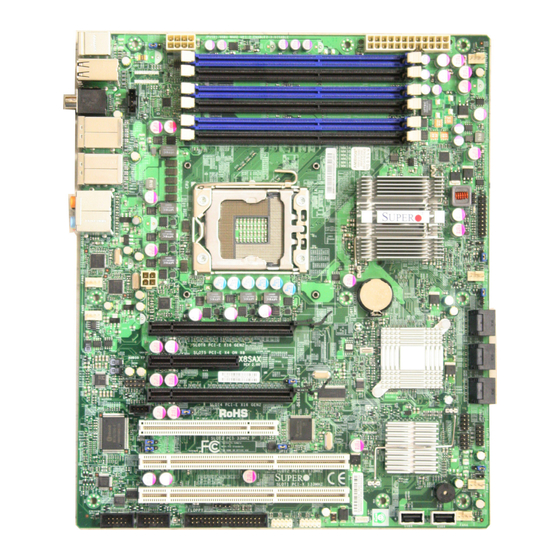
Checklist Thank you for purchasing your computer motherboard from an acknowledged leader in the industry. Supermicro boards are designed with the utmost attention to detail to provide you with the highest standards in quality and performance. Please check that the following items have all been included with your motherboard. - Page 10 X8SAX/C7X58 User’s Manual X8SAX Image Note: All graphics shown in this manual were based upon the latest PCB Revision available at the time of publishing of the manual. The motherboard you've received may or may not look exactly the same as the graphics shown in this manual.
-
Page 11: Motherboard Layout
Chapter 1: Introduction Motherboard Layout JPUSB1 JPW1 JPW2 DIMM3A Fan1 - CPU DIMM3B DIMM2A DIMM2B DIMM1A DIMM1B X8SAX Intel North Bridge LAN CTRL Fan6 LAN CTRL Fan2 JPW3 Battery Fan5 Slot6 PCI-E x16 Gen2 JBT1 Intel ICH10R BIOS Slot5 PCI-E x4 in x8 Gen1 South Bridge Audio FP Audio CTRL... -
Page 12: Default Setting
X8SAX/C7X58 User’s Manual X8SAX Quick Reference JPUSB1 JPW1 JPW2 DIMM3A Fan1 - CPU DIMM3B DIMM2A DIMM2B DIMM1A DIMM1B X8SAX Intel North Bridge LAN CTRL Fan6 LAN CTRL Fan2 JPW3 Battery Fan5 Slot6 PCI-E x16 Gen2 JBT1 Intel ICH10R BIOS Slot5 PCI-E x4 in x8 Gen1 South Bridge Audio FP Audio CTRL... - Page 13 Chapter 1: Introduction Connector Label Description 1394a_1/2 #25, 26 IEEE 1394a connection headers Audio FP Front panel audio header (HD) Audio (BP) High Definition Audio (7.1) header Battery Onboard battery (B1) CD-In Audio CD Input header COM1/COM2 #22, 21 COM1/2 Serial connection headers Fans 1~6 #8, 47, 36, 35, System/CPU fan headers (Fan 1: CPU fan) 54, 9...
-
Page 14: Motherboard Features
X8SAX/C7X58 User’s Manual Motherboard Features Single Intel ® Core™ i7 900 series, i7 Extreme Edition, and Intel® Xeon® • 5500/3500 series processors in an LGA1366 socket. Xeon® 5600/3600 series processors are supported on PCB Rev. 2.0 with BIOS 2.0 and above. Memory •... - Page 15 Chapter 1: Introduction Network Connections • Two Intel 82574L Gigabit (10/100/1000 Mb/s) Ethernet Controllers with two Gigabit LAN ports • Two (2) RJ-45 backplane connectors with Link and Activity LEDs built-in I/O Devices SATA Connections • Six (6) SATA ports supported by the Intel ICH10R SATA Controller •...
- Page 16 X8SAX/C7X58 User’s Manual PC Health Monitoring CPU Monitoring • Onboard voltage monitors for CPU core, Memory Voltage, Chipset Voltage, +1.8V, +3.3V, +3.3V standby, +5V, +5V, Standby, VBat and ±12V • CPU 6-Phase-switching voltage regulator • CPU/System overheat LED and control •...
- Page 17 Chapter 1: Introduction Notes...
- Page 18 X8SAX/C7X58 User’s Manual X8SAX / C7X58 Block Diagram DIMM_CH1 Intersil Intel DIMM_CH2 VRD 11.1 DIMM_CH3 QPI: Up to 6.40 GT/s DDR3:1600XMP/1333/1066/800 (1600XMP is supported on the C7X58 motherboard only, see page 3-3 for more information) PCIE_x16 PCI_E x16 Slot Intel PCIE_x16 PCI_E x16 Slot North Bridge...
-
Page 19: Chipset Overview
Chapter 1: Introduction Chipset Overview Built upon the functionality and the capability of the Intel X58 Express chipset, the X8SAX/C7X58 motherboard provides the performance and feature set required for dual-processor systems with configuration options optimized for intensive ap- plication and high-end workstation platforms. The main architecture of the X8SAX/C7X58 consists of an LGA 1366 processor socket, the Intel X58 Express North Bridge chipset, the ICH10R South Bridge, and the PXH/V IO Bridge. -
Page 20: Pc Health Monitoring
X8SAX/C7X58 User’s Manual PC Health Monitoring This section describes the PC health monitoring features of the X8SAX/C7X58. The motherboard has an onboard System Hardware Monitor chip that supports PC health monitoring. Recovery from AC Power Loss BIOS provides a setting for you to determine how the system will respond when AC power is lost and then restored to the system. -
Page 21: Slow Blinking Led For Suspend-State Indicator
Chapter 1: Introduction Slow Blinking LED for Suspend-State Indicator When the CPU goes into a suspend state, the chassis power LED will start blink- ing to indicate that the CPU is in the suspend mode. When the user presses any key, the CPU will wake-up and the LED indicator will automatically stop blinking and remain on. -
Page 22: Super I/O
X8SAX/C7X58 User’s Manual Super I/O The disk drive adapter functions of the Super I/O chip include a floppy disk drive controller that is compatible with industry standard 82077/765, a data separator, write pre-compensation circuitry, decode logic, data rate selection, a clock genera- tor, drive interface control logic and interrupt and DMA logic. The wide range of functions integrated onto the Super I/O greatly reduces the number of components required for interfacing with floppy disk drives. The Super I/O supports two 360 K, 720 K, 1.2 M, 1.44 M or 2.88 M disk drives and data transfer rates of 250 Kb/s,... -
Page 23: Chapter 2 Installation
Chapter 2: Installation Chapter 2 Installation Static-Sensitive Devices Electrostatic-Discharge (ESD) can damage electronic com ponents. To prevent dam- age to your system board, it is important to handle it very carefully. The following measures are generally sufficient to protect your equipment from ESD. Precautions • Use a grounded wrist strap designed to prevent static discharge. • Touch a grounded metal object before removing the board from the antistatic bag. -
Page 24: Processor And Heatsink Installation
X8SAX/C7X58 User's Manual Processor and Heatsink Installation When handling the processor package, avoid placing direct pressure on the label area of the fan. Notes: 1. Always connect the power cord last and always remove it before adding, re- moving or changing any hardware components. Make sure that you install the processor into the CPU socket before you install the CPU heatsink. - Page 25 Chapter 2: Installation 4. After removing the plastic cap, using your thumb and the index finger, hold the CPU at the north and south center edges. 5. Align the CPU key, the semi- circle cutout, against the socket key, the notch below the gold color dot on the side of the CPU Socket socket.
-
Page 26: Installing An Active Fan Cpu Heatsink
X8SAX/C7X58 User's Manual Installing an Active Fan CPU Heatsink 1. Locate the CPU Fan power con- nector on the motherboard. (Refer to Thermal Grease the layout on the right for the CPU Fan location.) 2. Position the heatsink so that the heatsink fan wires are closest to the CPU fan power connector and are not interfered with other components. -
Page 27: Removing The Heatsink
Chapter 2: Installation 7. Align the four heatsink fasten- ers with the mounting holes on the motherboard. Gently push the pairs of diagonal fasteners (#1 & #2, and #3 & #4) into the mounting holes until you hear a click. (Note: Make sure to orient each fastener so that the narrow end Narrow end of the groove of the groove is pointing outward.) -
Page 28: Installing A Passive Cpu Heatsink
X8SAX/C7X58 User's Manual Installing a Passive CPU Heatsink Note: Passive CPU Heatsinks that have been purchased from Supermicro will include the optional heatsink bracket. Heatsinks pur- chased elsewhere may not include this bracket, but is available sepa- rately from Supermicro. - Page 29 Chapter 2: Installation 5. Screw in two diagonal screws (i.e., the #1 and the #2 screws) until secure. However, leave each loosely tightened until all four screws are in place. 6. Finish the installation by fully tightening all four screws. Do Screw#1 Screw#2 not over-tighten to avoid pos-...
-
Page 30: Mounting The Motherboard Into The Chassis
X8SAX/C7X58 User's Manual Mounting the Motherboard into the Chassis All motherboards have standard mounting holes to fit different types of chassis. Make sure that the locations of all mounting holes for the motherboard and the chas- sis match. Although a chassis may have both plastic and metal mounting fasteners, metal ones are highly recommended because they ground the motherboard to the chassis. -
Page 31: Installing And Removing The Memory Modules
Chapter 2: Installation Installing and Removing the Memory Modules Note: Check the Supermicro web site for recommended memory modules. CAUTION Exercise extreme care when installing or removing DIMM modules to prevent any possible damage. Press down the release tabs Installing & Removing DIMMs 1. -
Page 32: Memory Support
X8SAX/C7X58 User's Manual Memory Support DIMM Module Population Configuration Maximum Memory Possible Single Rank UDIMMs - 12GB (6x 2GB DIMMs), Dual Rank UDIMMs - 24GB (6x 4GB DIMMs). See Note 5 on the next page for XMP memory support (C7X58 only). JPUSB1 JPW1 JPW2... - Page 33 Chapter 2: Installation Note 4: For Microsoft Windows users: Microsoft implemented a design change in Windows XP with Service Pack 2 (SP2) and Windows Vista. This change is specific to the Physical Address Extension (PAE) mode behavior which improves driver compatibility. For more information, please read the following article at Microsoft’s Knowledge Base website at: http://support.microsoft.
-
Page 34: Connectors/Io Ports
X8SAX/C7X58 User's Manual Connectors/IO Ports The I/O ports are color coded in conformance with the PC 99 specification. See the figure below for the colors and locations of the various I/O ports. Back Panel Connectors and IO Ports JPUSB1 JPW2 JPW1 DIMM3A Fan1 - CPU DIMM3B DIMM2A DIMM2B DIMM1A DIMM1B X8SAX Intel North Bridge LAN CTRL Fan6 LAN CTRL Fan2 JPW3 Battery Fan5 Slot6 PCI-E x16 Gen2 JBT1 Intel ICH10R BIOS... -
Page 35: Atx Ps/2 Keyboard And Ps/2 Mouse Ports
Chapter 2: Installation ATX PS/2 Keyboard and PS/2 PS/2 Keyboard/Mouse Pin Mouse Ports Definitions PS2 Keyboard PS2 Mouse The ATX PS/2 keyboard and PS/2 Pin# Definition Pin# Definition mouse are located next to the Back KB Data Mouse Data Panel USB Ports 1~2 on the moth- No Connection No Connection erboard. -
Page 36: Universal Serial Bus (Usb)
X8SAX/C7X58 User's Manual Universal Serial Bus (USB) Back Panel USB 0~3, 4/5, 6/7 Pin Definitions Eight Universal Serial Bus ports (USB Pin# Definition Pin# Definition 0~3, USB 4/5, USB 6/7) are located on the I/O back panel. USB Ports 4/5 are USB_PN1 USB_PN0 located below LAN Port1 port. USB USB_PP1 USB_PP0 6/7 are below LAN Port2. -
Page 37: Ethernet Ports
Chapter 2: Installation Ethernet Ports LAN Ports Pin Definition Two Ethernet ports are located at on Pin# Definition the IO backplane above the backpanel P2V5SB SGND USB ports. These ports accept RJ45 TD0+ Act LED type cables. (Note: Please refer to the TD0- P3V3SB LED Indicator Section for LAN LED... -
Page 38: High Definition Audio (Hda)
X8SAX/C7X58 User's Manual High Definition Audio (HDA) The X8SAX/C7X58 features a 7.1+2 Channel Orange: High Definition Audio (HDA) codec that pro- Blue: Line-In CEN/LFE vides 10 DAC channels, simultaneously sup- Black: Back Green: Front porting 7.1 sound playback and two channels Surround of independent stereo sound output (multiple Grey: Side Pink: Mic-In Surround... -
Page 39: Front Panel Audio Control
Chapter 2: Installation Front Panel Audio Control HD Front Panel Audio Pin Definitions When front panel headphones are plugged in, Pin# Signal the back panel audio output is disabled. This is MIC, Left Channel done through the FP Audio header (Audio FP). Ground If the front panel interface card is not connected MIC, Right Channel... -
Page 40: Serial Ports
X8SAX/C7X58 User's Manual Serial Ports Serial Port Pin Definitions (COM1/COM2) Two COM Port headers are located Pin # Definition Pin # Definition on the motherboard. See the table on the right for pin definitions. Ground Serial ATA Ports S i x Se ria l AT A ( S A TA) por t s (SATA0~SATA5) are located next SATA Port to the ICH10R on the motherboard. -
Page 41: Front Control Panel
These connectors are designed specifically for use with Supermicro server chassis. See the figure below for the descriptions of the various control panel buttons and LED indicators. Refer to the following section for descriptions and pin definitions. -
Page 42: Front Control Panel Pin Definitions
X8SAX/C7X58 User's Manual Front Control Panel Pin Definitions NMI Button NMI Button Pin Definitions (JF1) The non-maskable interrupt button Pin# Definition header is located on pins 19 and 20 Control of JF1. Refer to the table on the right Ground for pin definitions. Power LED Power LED Pin Definitions (JF1) The Power LED connection is located Pin# Definition on pins 15 and 16 of JF1. -
Page 43: Hdd Led
Chapter 2: Installation HDD LED The HDD LED connection is located HDD LED Pin Definitions (JF1) on pins 13 and 14 of JF1. Attach a Pin# Definition hard drive LED cable here to display disk activity detected on the mother- HD Active board's built-in disk controllers (for any hard drive activities on the sys- tem, including Serial ATA and IDE). -
Page 44: Overheat (Oh)/Fan Fail Led
X8SAX/C7X58 User's Manual Overheat (OH)/Fan Fail LED OH/Fan Fail LED Pin Definitions (JF1) Connect an LED cable to the OH/ Pin# Definition Fan Fail connection on pins 7 and 8 of JF1 to provide advanced warnings Ground for chassis overheat or fan failure. OH/Fan Fail Indicator Refer to the table on the right for pin Status... -
Page 45: Reset Button
Chapter 2: Installation Reset Button Reset Button The Reset Button connection is located Pin Definitions (JF1) on pins 3 and 4 of JF1. Attach it to a Pin# Definition hardware reset switch on the computer Reset case to reset the system. Refer to the Ground table on the right for pin definitions. -
Page 46: Connecting Cables
X8SAX/C7X58 User's Manual Connecting Cables This section provides brief descriptions and pin-out definitions for onboard headers and connectors. Be sure to use the correct cable for each header or connector. • For information on Backpanel USB and Front Panel USB ports, refer to Page 2-9. • For information on COM Port 1 and COM Port 2, please see Page 2-10. ATX Power 24-pin Connector ATX Main PWR &... -
Page 47: Fan Headers
Chapter 2: Installation Fan Headers The X8SAX/C7X58 has six fan headers Fan Header (Fan1 ~ Fan6). Fans 2~6 are system Pin Definitions cooling fans. Fan 1 is used as a CPU Pin# Definition fan. These fans are 4-pin fan headers. Ground (Black) However, Pins 1-3 of the fan headers are 2.5A/+16V (Red) -
Page 48: Internal Buzzer
X8SAX/C7X58 User's Manual Internal Buzzer Internal Buzzer (SP1) Pin Definition The Internal Buzzer (SP1) can be Pin# Definitions used to provide audible indications Pin 1 Pos. (+) Beep In for various beep codes. See the table Pin 2 Neg. (-) Alarm on the right for pin definitions. Refer Speaker to the layout below for the locations of the Internal Buzzer (SP1). -
Page 49: Overheat/Fan Fail Led
Chapter 2: Installation Overheat/Fan Fail LED (JOH1 Overheat LED Pin Definitions The JOH1 header is used to connect Pin# Definition an LED to provide warnings of chas- 5vDC sis overheat. This LED will also blink OH Active to indicate a fan failure. Refer to the table on right for pin definitions. -
Page 50: Power Supply I C Connector
X8SAX/C7X58 User's Manual Power Supply I C Connector PWR Supply I Pin Definitions Power Supply (I C) Connector moni- Pin# Definition tors the status of the power supply, Clock fan and system temperature. See the Data table on the right for pin definitions. PWR Fail Ground Onboard Power LED Onboard PWR LED Pin Definitions An onboard Power LED header is... -
Page 51: 1394A_1/1394A_2 Connections
Chapter 2: Installation 1394a_1/1394a_2 Connections 1394a_1 Pin Definitions 1394a_1 and 1394a_2 provide the Pin# Defin. Pin# Defin IEEE 1394 connections on the moth- PTPA0+ PTPA0- erboard. See the tables on the right for pin definitions. PTPB0+ PTPB0- PWR 1394 PWR 1394 J1394a_2 Pin Definitions Pin# Defin. -
Page 52: Wake-On-Ring
X8SAX/C7X58 User's Manual Wake-On-Ring Wake-On-Ring Pin Definitions The Wake-On-Ring header is des- (JWOR) ignated JWOR. This function allows Pin# Definition your computer to wake up when Ground receiving an incoming call to the Wake-up modem when in the suspend state. See the table on the right for pin definitions. You must have a Wake- On-Ring card and cable to use this feature. -
Page 53: Jumper Settings
Chapter 2: Installation Jumper Settings Explanation of Jumpers To modify the operation of the mother- board, jumpers can be used to choose between optional settings. Jumpers cre- ate shorts between two pins to change the function of the connector. Pin 1 is identified with a square solder pad on the printed circuit board. -
Page 54: Cmos Clear
X8SAX/C7X58 User's Manual CMOS Clear JBT1 is used to clear CMOS. Instead of pins, this "jumper" consists of contact pads to prevent accidental clearing of CMOS. To clear CMOS, use a metal object such as a small screwdriver to touch both pads at the same time to short the connection. Always remove the AC power cord from the system before clearing CMOS. -
Page 55: Smb To Pci-X/Pci-E Slots Speeds
Chapter 2: Installation SMB to PCI-X/PCI-E Slots Speeds SMBus to PCI-X/PCI-Exp Slots Use Jumper JI C1 to connect the System Jumper Settings Management Bus to the PCI slots, and Jumper Setting Definition Jumper JI C2, to the PCI-Exp. slots in Pins 1-2 Enabled order to improve power management Pins 2-3 (Default) -
Page 56: Audio Enable
X8SAX/C7X58 User's Manual Audio Enable Audio Enable (JPAC) JPAC enables or disables the onboard audio Pin# Definition connections. See the table on the right Enabled (default) for jumper settings. The default setting is Disabled Enabled. USB Wake-Up Use JPUSB jumpers to "wake-up" your sys- tem by pressing a key on a USB keyboard or JPUSB1 (BackPanel USB Wake-up) -
Page 57: Onboard Indicators
Chapter 2: Installation Onboard Indicators GLAN Link/Speed LED Indicator Lan Port LEDs LED Color Definition Two LAN ports are located on the I/O No Connection or 10 Mbps Backplane. Each LAN port has two LEDs. Green (On) 100 Mbps The yellow GLAN Activity LED (see be- Amber (On) 1 Gbps low) indicates activity, while the GLAN... -
Page 58: Serial Ata And Floppy Drive Connections
X8SAX/C7X58 User's Manual Serial ATA and Floppy Drive Connections Note the following conditions when connecting the Serial ATA and floppy disk drive cables: • Be sure to use the correct cable for each connector. Refer to Page 1-1 for cables that came with your shipment. • A red mark on a wire indicates the location of pin 1. SATA Connectors SATA Connectors Six Serial ATA (SATA) connectors (I-SATA Pin Definitions 0~5) are located on the motherboard Pin# Signal to provide serial link connections. Se- Ground SATA_TXP rial Link connections provide faster data... -
Page 59: Floppy Connector
Chapter 2: Installation Floppy Connector Floppy Drive Connector Pin Definitions The floppy connector is located near Pin# Definition Pin # Definition the PCI-X Slot 1 on the motherboard. Ground FDHDIN See the table on the right for pin Ground Reserved definitions. FDEDIN Ground Index Note the following when con- Ground Motor Enable necting the floppy cable:... - Page 60 X8SAX/C7X58 User's Manual Notes 2-38...
-
Page 61: Chapter 3 Troubleshooting
Chapter 3: Troubleshooting Chapter 3 Troubleshooting Troubleshooting Procedures Use the following procedures to troubleshoot your system. If you have followed all of the procedures below and still need assistance, refer to the ‘Technical Support Procedures’ and/or ‘Returning Merchandise for Service’ section(s) in this chapter. Always disconnect the AC power cord before adding, changing or installing any hardware components. -
Page 62: Memory Errors
Technical Support Procedures Before contacting Technical Support, please make sure that you have followed all the steps listed below. Also, Note that as a motherboard manufacturer, Supermicro does not sell directly to end users, so it is best to first check with your distributor or reseller for troubleshooting services. They should know of any possible problem(s) with the specific system configuration that was sold to you. -
Page 63: Frequently Asked Questions
Note: Not all BIOS can be flashed. Some cannot be flashed; it depends on the modifications to the boot block code. 3. If you've followed the instructions above to troubleshoot your system, and still cannot resolve the problem, then contact Supermicro's technical support and provide them with the following information: • M otherboard model and PCB revision number • B IOS release date/version (this can be seen on the initial display when your... - Page 64 Answer: It is recommended that you do not upgrade your BIOS if you are not experiencing any problems with your system. Updated BIOS files are located on our web site at http://www.supermicro.com/support/bios/. Please check our BIOS warning message and the information on how to update your BIOS on our web site. Select your motherboard model and download the BIOS (.rom) file to...
-
Page 65: Returning Merchandise For Service
Note: The SPI BIOS chip installed on this motherboard is not removable. To repair or replace a damaged BIOS chip, please send your motherboard to RMA at Supermicro for service. Question: I think my BIOS is corrupted. How can I recover my BIOS? Answer: Please see Appendix D, BIOS Recovery for detailed instructions. - Page 66 X8SAX/C7X58 User's Manual Notes...
-
Page 67: Chapter 4 Bios
When an option is selected in the left frame, it is highlighted in white. Often a text message will accompany it. (Note: the AMI BIOS has default text messages built in. Supermicro retains the option to include, omit, or change any of these text messages.) The AMI BIOS Setup Utility uses a key-based navigation system called "hot keys". -
Page 68: Main Setup
Warning! Do not upgrade the BIOS unless your system has a BIOS-related issue. Flashing the wrong BIOS can cause irreparable damage to the system. In no event shall Supermicro be liable for direct, indirect, special, incidental, or consequential damages arising from a BIOS update. If you have to update the BIOS, do not shut down or reset the system while the BIOS is updating. - Page 69 Date using the arrow keys. Enter new values through the keyboard. Press the <Tab> key or the arrow keys to move between fields. The date must be entered in Day MM/DD/YY format. The time is entered in HH:MM:SS format. (Note: The time is in the 24-hour format. For example, 5:30 P.M. appears as 17:30:00.) Supermicro X8SAX/C7X58 Version Build Date Processor...
-
Page 70: 4-3 Advanced Setup Configurations
X8SAX/C7X58 4-3 Advanced Setup Configurations Use the arrow keys to select Boot Setup and hit <Enter> to access the submenu items: BIOS SETUP UTILTY Main Advanced Security Boot Exit Advanced Settings Configure Settings during System Boot. Boot Feature Processor & Clock Options Advanced Chipset Control IDE/Floppy Configuration PCI/PnP Configuration Super IO Configuration Remote Access Configuration Hardware Health Configuration ACPI Configuration Event Log Configuration Select Screen... - Page 71 Chapter 4: AMI BIOS Wait For 'F1' If Error This forces the system to wait until the 'F1' key is pressed if an error occurs. The options are Disabled and Enabled. Hit 'Del' Message Display This feature displays "Press DEL to run Setup" during POST. The options are Enabled and Disabled.
- Page 72 X8SAX/C7X58 Processor & Clock Options Warning : Take Caution when changing the Advanced settings. An incorrect value, a very high DRAM frequency or incorrect DRAM timing may cause system to become unstable. When this occurs, revert to the default setting. CPU Ratio This feature allows the user to use the CPU clock multiplier to multiply CPU speed in order to enhance performance.
- Page 73 Chapter 4: AMI BIOS Execute-Disable Bit Capability (Available when supported by the OS and the CPU) Set to Enabled to enable the Execute Disable Bit which will allow the processor to designate areas in the system memory where an application code can execute and where it cannot, thus preventing a worm or a virus from flooding illegal codes to overwhelm the processor or damage the system during an attack.
-
Page 74: Advanced Chipset Control
X8SAX/C7X58 C-State package limit setting If set to Auto, the AMI BIOS will automatically set the limit on the C-State package register. The options are Auto, C1, C3, C6 and C7. C1 Auto Demotion When enabled, the CPU will conditionally demote C3, C6 or C7 requests to C1 based on un-core auto-demote information. - Page 75 Chapter 4: AMI BIOS QPI L0s and L1 QuickPath Interconnect (QPI) offers three power states called L0, L0s and L0 is a normal operational state where data and control packets can be transmitted and received. All power management states are entered from this state.
- Page 76 X8SAX/C7X58 Patrol Scrubbing Patrol Scrubbing is a process that allows the CPU to correct correctable memory errors detected on a memory module and send the correction to the requestor (the original source). When this item is set to Enabled, the North Bridge will read and write back one cache line every 16K cycles, if there is no delay caused by internal processing.
- Page 77 Chapter 4: AMI BIOS Active State Power Management Select Enabled to start Active-State Power Management for signal transactions between L0 and L1 Links on the PCI Express Bus. This maximizes power-saving and transaction speed. The options are Enabled and Disabled. Route Port 80h Cycles to This feature allows the user to decide which bus to send debug information to.
- Page 78 X8SAX/C7X58 Configure SATA#1 as This feature allows the user to select the drive type for SATA#1. The options are IDE, RAID and AHCI. ICH RAID CodeBase (Available if RAID is selected above) Select Intel to enable the Intel SATA Host RAID Utility. Select Adaptec to use the Adaptec Host RAID Utility.
- Page 79 Chapter 4: AMI BIOS Disabled to allow data to be transferred from and to the device one sector at a time. Select Auto to allow data transfer from and to the device occur multiple sectors at a time if the device supports it. The options are Auto and Disabled. PIO Mode The IDE PIO (Programmable I/O) Mode programs timing cycles between the IDE drive and the programmable IDE controller.
- Page 80 X8SAX/C7X58 Select UDMA0 to allow the BIOS to use Ultra DMA mode 0. It has a data transfer rate of 16.6 MB/s. It has the same transfer rate as PIO mode 4 and Multi Word DMA mode 2. Select UDMA1 to allow the BIOS to use Ultra DMA mode 1. It has a data transfer rate of 25 MB/s.
- Page 81 Chapter 4: AMI BIOS PCI Latency Timer This feature sets the latency Timer of each PCI device installed on a PCI bus. Select 64 to set the PCI latency to 64 PCI clock cycles. The options are 32, 64, 96, 128, 160, 192, 224 and 248.
- Page 82 X8SAX/C7X58 accessing any system resources. When this option is set to Disabled, the serial port physically becomes unavailable. Select 3F8/IRQ4 to allow the serial port to use 3F8 as its I/O port address and IRQ 4 for the interrupt address. The options for Serial Port1 are Disabled, 3F8/IRQ4, 3E8/IRQ4, and 2E8/IRQ3.
-
Page 83: Hardware Health Configuration
Chapter 4: AMI BIOS Select Boot Loader to keep Console Redirection active during POST and Boot Loader. The options are Disabled, Boot Loader, and Always. Terminal Type This feature allows the user to select the target terminal type for Console Redi- rection. - Page 84 X8SAX/C7X58 CPU Temperature/System Temperature This feature displays current temperature readings for the CPU and the System. The following items will be displayed for your reference only: CPU Temperature The CPU Temperature feature will display the CPU temperature status as detected by the BIOS: Low –...
- Page 85 Tolerances’, the installed CPU can now send its ‘Temperature Toler- ance’ to the motherboard resulting in better CPU thermal management. Supermicro has leveraged this feature by assigning a temperature status to certain thermal conditions in the processor (Low, Medium and High). This makes it easier for the user to understand the CPU’s temperature status,...
- Page 86 X8SAX/C7X58 of PWM Cycle), Balanced/BL (@50% of PWM Cycle), and Energy Saving/ES (@30% of PWM Cycle). Voltage Reading This feature displays the current voltage detected of the various components in the system: Vcore, VDIMM, 5V, 12V, -12V, 3.3Vcc, 3.3VSB, VBAT, Vtt ACPI Configuration Use this feature to configure Advanced Configuration and Power Interface (ACPI) power management settings for your system.
- Page 87 Chapter 4: AMI BIOS ACPI APIC Support Select Enabled to include the ACPI APIC Table Pointer in the RSDT (Root System Description Table) pointer list. The options are Enabled and Disabled. APIC ACPI SCI IRQ When this item is set to Enabled, APIC ACPI SCI IRQ is supported by the system. The options are Enabled and Disabled.
-
Page 88: Security Settings
X8SAX/C7X58 Security Settings The AMI BIOS provides a Supervisor and a User password. If you use both pass- words, the Supervisor password must be set first. BIOS SETUP UTILTY Main Advanced Security Boot Exit Security Settings Install or Change the password. Supervisor Password : Installed User Password : Installed Change Supervisor Password User Access Level... -
Page 89: 4-5 Boot Configuration
Chapter 4: AMI BIOS Clear User Password (Available only if User Password has been set) Password Check Available options are Setup and Always. Boot Sector Virus Protection When Enabled, the AMI BOIS displays a warning when any program (or virus) is- sues a Disk Format command or attempts to write to the boot sector of the hard disk drive. -
Page 90: Exit Options
X8SAX/C7X58 Hard Disk Drives This feature allows the user to specify the boot sequence from all available hard disk drives. The settings are Disabled and a list of all hard disk drives that have been detected (i.e., 1st Drive, 2nd Drive, 3rd Drive, etc). Removable Drives This feature allows the user to specify the boot sequence from available Removable Drives. - Page 91 Chapter 4: AMI BIOS figuration parameters can take effect. Select Save Changes and Exit from the Exit menu and press <Enter>. Discard Changes and Exit Select this option to quit the BIOS Setup without making any permanent changes to the system configuration, and reboot the computer. Select Discard Changes and Exit from the Exit menu and press <Enter>. Discard Changes Select this option and press <Enter> to discard all the changes and return to the AMI BIOS Utility Program. Load Optimal Defaults To set this feature, select Load Optimal Defaults from the Exit menu and press <Enter>. Then, select OK to allow the AMI BIOS to automatically load Optimal De- faults to the BIOS Settings.
- Page 92 X8SAX/C7X58 Notes 4-26...
-
Page 93: Appendix A Post Error Beep Codes
Appendix A: POST Error Beep Codes Appendix A POST Error Beep Codes This section lists POST (Power On Self Test) error beep codes for the AMI BIOS. POST error beep codes are divided into two categories: recoverable and terminal. This section lists Beep Codes for recoverable POST errors. Recoverable POST Error Beep Codes When a recoverable type of error occurs during POST, BIOS will display a POST code that describes the problem. - Page 94 X8SAX/C7X58 User's Manual Notes...
-
Page 95: Appendix B Software Installation Instructions
To install these software programs and drivers, click the icons to the right of these items. (Note: To install the Windows OS, please refer to the Windows OS Installation Guide posted at http://www.supermicro.com/support/manuals/.) Driver/Tool Installation Display Screen Note : Click the icons showing a hand writing on the paper to view the readme files for each item. Click a computer icon to the right of an item to install an... -
Page 96: Configuring Supero Doctor Iii
X8SAX/C7X58 User’s Manual B-2 Configuring SuperDoctor ® The SuperDoctor III program is a Web-based management tool that supports remote management capability. It includes Remote and Local Management tools. The local management tool is called the SD III Client. The SuperDoctor III program included on the CDROM that came with your motherboard allows you to monitor the envi- ronment and operations of your system. - Page 97 SuperDoctor III Interface Display Screen-II (Remote Control) Note: The SuperDoctor III software and manual may be downloaded from our Website at: http://www.supermicro.com/products/accessories/software/SuperDoctorIII.cfm. For Linux, we still recommend that you use SuperDoctor II, this version is also available for download at the link above.
- Page 98 X8SAX/C7X58 User’s Manual Notes...
-
Page 99: Appendix C - Bios Recovery
The recovery procedure described in this section is to be used only when advised by your Supermicro Technical Support representative, or in cases of emergencies where the system no longer can boot due to a corrupted BIOS. DO NOT re-program (re-flash) the BIOS if your system is running properly. -
Page 100: Recovery Process From An Ide/Sata Atapi Disc Driv
X8SAX/C7X58 User's Manual When the Boot Sector Recovery Process is complete, the system will reboot automatically and you will see a checksum error on your screen. Part 2 - BIOS Reprogramming (Re-Flashing) After completing the Boot Sector Recovery Process, you will need to reprogram (“re-flash”) the proper BIOS binary file again into the BIOS ROM in order to have the correct BIOS file loaded by the system. For details on how to flash/re-flash a BIOS, please check our website for “Update your BIOS”, or see the section 3-3... - Page 101 (Disclaimer) The products sold by Supermicro are not intended for and will not be used in life support systems, medical equipment, nuclear facilities or systems, aircraft, aircraft devices, aircraft/emergency communication devices or other critical systems whose failure to perform be reasonably expected to result in significant injury or loss of life or catastrophic property damage. Accordingly, Supermicro disclaims any and all liability, and should buyer use or sell such products for use in such ultra-hazardous applications, it does so entirely at its own risk.
Need help?
Do you have a question about the Supero X8SAX and is the answer not in the manual?
Questions and answers