Table of Contents
Advertisement
Quick Links
Advertisement
Table of Contents

Subscribe to Our Youtube Channel
Related Manuals for Supero C7B250-CB-MK


Summary of Contents for Supero C7B250-CB-MK
- Page 1 C7B250-CB-MK USER’S MANUAL Revision 1.0...
- Page 2 The information in this user’s manual has been carefully reviewed and is believed to be accurate. The vendor assumes no responsibility for any inaccuracies that may be contained in this document, makes no commitment to update or to keep current the information in this manual, or to notify any person or organization of the updates.
-
Page 3: Manual Organization
This manual is written for system integrators, PC technicians and knowledgeable PC users. It provides information for the installation and use of the C7B250-CB-MK motherboard. Manual Organization Chapter 1 describes the features, specifications and performance of the motherboard, and provides detailed information on the Intel B250 Express chipset. -
Page 4: Checklist
Supermicro C7B250-CB-MK Motherboard User’s Manual Checklist Congratulations on purchasing your computer motherboard from an ac- knowledged leader in the industry. Supermicro boards are designed with the utmost attention to detail to provide you with the highest standards in quality and performance. -
Page 5: Standardized Warning Statements
Standardized Warning Statements Standardized Warning Statements The following statements are industry-standard warnings, provided to warn the user of situations which have the potential for bodily injury. Should you have questions or experience difficulty, contact Supermicro's Technical Support department for assistance. Only certified technicians should attempt to install or configure components. -
Page 6: Product Disposal
Supermicro C7B250-CB-MK Motherboard User’s Manual ¡Advertencia! Existe peligro de explosión si la batería se reemplaza de manera incor- recta. Reemplazar la batería exclusivamente con el mismo tipo o el equivalente recomendado por el fabricante. Desechar las baterías gasta- das según las instrucciones del fabricante. - Page 7 Standardized Warning Statements 製品の廃棄 この製品を廃棄処分する場合、 国の関係する全ての法律 ・ 条例に従い処理する必要が あり ます。 警告 本产品的废弃处理应根据所有国家的法律和规章进行。 警告 本產品的廢棄處理應根據所有國家的法律和規章進行。 Warnung Die Entsorgung dieses Produkts sollte gemäß allen Bestimmungen und Gesetzen des Landes erfolgen. ¡Advertencia! Al deshacerse por completo de este producto debe seguir todas las leyes y reglamentos nacionales.
-
Page 8: Contacting Supermicro
Supermicro C7B250-CB-MK Motherboard User’s Manual Contacting Supermicro Headquarters Address: Super Micro Computer, Inc. 980 Rock Ave. San Jose, CA 95131 U.S.A. Tel: +1 (408) 503-8000 Fax: +1 (408) 503-8008 Email: marketing@supermicro.com (General Information) support@supermicro.com (Technical Support) Web Site: www.supermicro.com Europe Address: Super Micro Computer B.V. -
Page 9: Where To Find More Information
Contacting Supermicro Where to Find More Information For your system to work properly, please follow the links below to download all necessary drivers/utilities and the user's manual for your motherboard. SMCI product manuals: http://www.supermicro.com/support/manuals/ Product Drivers and utilities: ftp://ftp.supermicro.com/ If you have any questions, please contact our support team at support@ supermicro.com. -
Page 10: Table Of Contents
Supermicro C7B250-CB-MK Motherboard User’s Manual Table of Contents Preface Manual Organization ................iii Checklist ..................iv Conventions Used in the Manual ............iv Standardized Warning Statements ............v Battery Handling ............... v Product Disposal ...............vi Contacting Supermicro ..............viii Where to Find More Information............ix Chapter 1 Introduction Overview ................ - Page 11 Table of Contents Removing Memory Modules ............. 2-9 Memory Support ..............2-10 Memory Population Guidelines ..........2-11 Motherboard Installation ............2-12 Tools Needed ............... 2-12 Location of Mounting Holes ........... 2-12 Installing the Motherboard ............ 2-13 Connector and I/O Ports ............2-14 I/O Back Panel ..............
- Page 12 Supermicro C7B250-CB-MK Motherboard User’s Manual JCMOS & JBT1 ..............2-28 PCI-E Slot SMB Enable (I2C1/I2C2) ........2-28 Watch Dog Timer Enable/Disable ........2-29 BIOS Recovery Jumper ............. 2-29 USB Wake Up ..............2-30 2-9 Onboard Indicators ..............2-31 LAN LEDs ................ 2-31 Onboard Power LED ............
- Page 13 Table of Contents Adjacent Cache Line Prefetch ..........4-6 Intel® (VMX) Virtualization Technology ........ 4-6 Active Processor Cores ............4-6 Hyper-Threading ..............4-7 BIST ................. 4-7 AES .................. 4-7 Machine Check ..............4-7 MonitorMWait ..............4-7 Intel® Trusted Executed Technology ........4-7 Alias Check Request ............
- Page 14 Supermicro C7B250-CB-MK Motherboard User’s Manual Fast Boot ................ 4-13 Quiet Boot ..............4-13 Bootup Num-Lock ............4-13 Wait for "F1" If Error ............4-13 Re-try Boot ..............4-13 Watch Dog Function ............4-14 Power Button Function ............4-14 AC Loss Policy Depend On ..........4-14 EuP Support ..............
- Page 15 Table of Contents Cdynmax Clamping Enable ..........4-23 Graphics Clock Frequency ..........4-23 PCH-IO Configuration ............4-24 SATA and RST Configuration..........4-25 SATA Controllers .............. 4-25 SATA Mode Selection ............4-25 SATA Controller Speed ............4-25 SATA Frozen ..............4-25 Serial ATA Port..............
- Page 16 Supermicro C7B250-CB-MK Motherboard User’s Manual Forbidden Signatures ............4-36 Append Forbidden Signature ..........4-36 Delete Authorized TimeStamps .......... 4-36 Authorized TimeStamps ............ 4-36 Append Authorized TimeStamp .......... 4-36 Delete OSRecovery Signatures ........... 4-37 OsRecovery Signatures ............. 4-37 Append OsRecovery Signature ........... 4-37 Thermal &...
-
Page 17: Chapter 1 Introduction
Chapter 1 Introduction 1-1 Overview About this Motherboard The C7B250-CB-MK motherboard supports a single 6th and 7th Genera- tion Intel® Core i7/i5/i3, Pentium®/Celeron® processor in an LGA 1151 (H4) socket. With the Intel B250 Express chipset built in, the C7B250-CB-MK motherboard offers substantial system performance and storage capability for overclocking platforms in a small form factor. -
Page 18: Motherboard Features
Supermicro C7B250-CB-MK Motherboard User’s Manual 1-3 Motherboard Features Single 6th and 7th Generation Intel® Core i7/i5/ i3, Pentium®/Celeron® processor in an LGA1151 type socket, up to 65W TDP. Two (2) slots support up to 32GB of unbuffered, non- Memory ECC, 2400MHz DDR4 memory... - Page 19 Chapter 1: Introduction Super I/O Nuvoton NCT6792D-B 128 Mb AMI BIOS SPI Flash BIOS BIOS ® Plug and Play (PnP), DMI 2.8, PCI 2.3, ACPI 1.0/2.0/3.0, and USB Keyboard ACPI/ASPM Power Management Power Configuration Main Switch Override Mechanism Internal/External Modem Ring-On Power-on mode for AC power recovery Health CPU Monitoring...
-
Page 20: Special Features
Supermicro C7B250-CB-MK Motherboard User’s Manual 1-4 Special Features Recovery from AC Power Loss Basic I/O System (BIOS) provides a setting for you to determine how the system will respond when AC power is lost and then restored to the system. You can choose for the system to remain powered off, (in which case you must press the power switch to turn it back on), or for it to automatically return to a power-on state. -
Page 21: System Resource Alert
Chapter 1: Introduction System Resource Alert This feature is available when the system is used with SuperDoctor 5 in the Windows OS environment or used with SuperDoctor II in Linux. SuperDoctor is used to notify the user of certain system events. For example, you can configure SuperDoctor to provide you with warnings when the system temperature, CPU temperatures, voltages and fan speeds go beyond predefined thresholds. -
Page 22: Power Supply
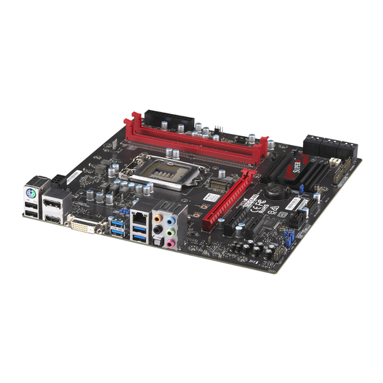
Supermicro C7B250-CB-MK Motherboard User’s Manual 1-7 Power Supply As with all computer products, a stable power source is necessary for proper and reliable operation. It is even more important for processors that have high CPU clock rates. This motherboard accommodates 24-pin ATX power supplies. Although most power supplies generally meet the specifications required by the CPU, some are inadequate. - Page 23 Chapter 1: Introduction C7B250-CB-MK Motherboard Image Note: All graphics shown in this manual were based upon the latest PCB Revision available at the time of publishing of the manual. The motherboard you've received may or may not look exactly the same...
- Page 24 Supermicro C7B250-CB-MK Motherboard User’s Manual C7B250-CB-MK Block Diagram SVID IMVP8 IMVP8 PCIe x16 SLOT #6 PCIe3.0_x8 PCIe3.0_x16 8.0GT/s 8.0GT/s PCIe x8(in x16) SLOT #6 2400/2133MHz INTEL LGA1151 DDR4 (CHA) DDI1 (Socket-H4) HDMI DDI 1 DIMMA2 DDI2 Display Port DDI 2...
- Page 25 Chapter 1: Introduction C7B250-CB-MK Motherboard Layout JPUSB1 JPW2 CPU_FAN1 J9701 J9702 JI2C2 JI2C1 SYS_FAN2 CPU SLOT3 PCI-E 3.0 X16 JSPDIF_OUT C7B250-CB-MK PCH SLOT2 PCI-E 3.0 X4 REV: 1.00 DESIGNED IN USA PCH SLOT1 PCI-E 3.0 X1 BAR CODE COM1 MAC CODE...
- Page 26 Supermicro C7B250-CB-MK Motherboard User’s Manual C7B250-CB-MK Quick Reference JPUSB1 JPW2 CPU_FAN1 J9701 J9702 JI2C2 JI2C1 SYS_FAN2 CPU SLOT3 PCI-E 3.0 X16 JSPDIF_OUT C7B250-CB-MK PCH SLOT2 PCI-E 3.0 X4 REV: 1.00 DESIGNED IN USA PCH SLOT1 PCI-E 3.0 X1 BAR CODE...
- Page 27 Chapter 1: Introduction Connector Description AUDIO FP Front Panel Audio Header Onboard Battery COM1 COM1 Port Header CPU_FAN1 CPU Fan Header Digital Video Interface Port HD AUDIO Back Panel HD Audio Ports HDMI/DP High Definition Multimedia Interface/DisplayPort I-SATA0~5 Intel® PCH Serial ATA (SATA) 3.0 Ports 0~5 (6Gb/sec) Pin 1~4: External Speaker Front Control Panel Header Chassis Intrusion Header...
- Page 28 Supermicro C7B250-CB-MK Motherboard User’s Manual Notes 1-12...
-
Page 29: Chapter 2 Installation
Chapter 2: Installation Chapter 2 Installation 2-1 Installation Components and Tools Needed Screws Phillips-Head Screwdriver Intel LGA 1151 Processor DDR4 DIMMs PC Chassis Heatsink with Fan Power Supply Video Card (Optional) SATA/USB Optical Drive (Optional) SATA Hard Disk Drive... -
Page 30: Static-Sensitive Devices
Supermicro C7B250-CB-MK Motherboard User’s Manual 2-2 Static-Sensitive Devices Electrostatic-Discharge (ESD) can damage electronic com ponents. To avoid damaging your system board, it is important to handle it very carefully. The following measures are generally sufficient to protect your equipment from ESD. -
Page 31: Processor And Heatsink Installation
Chapter 2: Installation 2-3 Processor and Heatsink Installation Attention! When handling the processor package, avoid placing direct pressure on the label area of the fan. Important: Always connect the power cord last, and always remove it before adding, removing or changing any hardware components. Make sure that you install the processor into the CPU socket before you install the CPU heatsink. - Page 32 Supermicro C7B250-CB-MK Motherboard User’s Manual 2. Gently lift the load lever to open the load plate. Remove the plas- tic cap. 3. Use your thumb and your index finger to hold the CPU at the North center edge and the South center edge of the CPU.
- Page 33 Chapter 2: Installation 5. Do not rub the CPU against the surface or against any pins of the socket to avoid damaging the CPU or the socket.) 6. With the CPU inside the socket, inspect the four corners of the CPU to make sure that the CPU is properly installed.
-
Page 34: Installing An Active Cpu Heatsink With Fan
Supermicro C7B250-CB-MK Motherboard User’s Manual Installing an Active CPU Heatsink with Fan 1. Locate the CPU Fan power con- nector on the motherboard. (Refer to the layout on the right for the CPU Fan location.) 2. Position the heatsink so that... - Page 35 Chapter 2: Installation between the fan wires and the fins of the heatsink. 7. Align the four heatsink fasteners with the mounting holes on the motherboard. Gently push the pairs of diagonal fasteners (#1 & #2, and #3 & #4) into the mounting holes until you hear a click.
-
Page 36: Removing The Heatsink
Supermicro C7B250-CB-MK Motherboard User’s Manual Removing the Heatsink Attention! We do not recommend that the CPU or the heatsink be removed. However, if you do need to remove the heatsink, please follow the instructions below to re- move the heatsink and to prevent damage done to the CPU or other components. -
Page 37: Installing Ddr4 Memory
Chapter 2: Installation 2-4 Installing DDR4 Memory Note: Check the Supermicro website for recommended memory modules. Attention! Exercise extreme care when installing or removing DIMM modules to prevent any possible damage. DIMM Installation USB 4/5 HDMI/DP HD AUDIO (3.0) KB/MOUSE USB 0/1 USB 6/7(3.0) JVR1... -
Page 38: Memory Support
DIMMB2 (Red Slot) Towards the edge of the motherboard The C7B250-CB-MK supports up to 32GB of Unbuffered (UDIMM) non- ECC DDR4 memory, up to 2400MHz in two 288-pin memory slots. Populating these DIMM modules with a pair of memory modules of the same type and same size will result in interleaved memory, which will improve memory performance. -
Page 39: Memory Population Guidelines
Chapter 2: Installation Possible System Memory Allocation & Availability System Device Size Physical Memory Remaining (-Available) (4 GB Total System Memory) Firmware Hub flash memory (System BIOS) 1 MB 3.99 Local APIC 4 KB 3.99 Area Reserved for the chipset 2 MB 3.99 I/O APIC (4 Kbytes) -
Page 40: Motherboard Installation
Supermicro C7B250-CB-MK Motherboard User’s Manual 2-5 Motherboard Installation All motherboards have standard mounting holes to fit different types of chassis. Make sure that the locations of all the mounting holes for both motherboard and chassis match. Although a chassis may have both plas- tic and metal mounting fasteners, metal ones are highly recommended because they ground the motherboard to the chassis. -
Page 41: Installing The Motherboard
Chapter 2: Installation Installing the Motherboard 1. Install the I/O shield into the back of the chassis. 2. Locate the mounting holes on the motherboard. See the previous page. 3. Locate the matching mounting holes on the chassis. Align the mounting holes on the motherboard against the mounting holes on the chassis. -
Page 42: Connector And I/O Ports
Supermicro C7B250-CB-MK Motherboard User’s Manual 2-6 Connector and I/O Ports The I/O ports are color coded in conformance with the industry standards. See the figure below for the colors and locations of the various I/O ports. I/O Back Panel USB 4/5... -
Page 43: Universal Serial Bus (Usb)
Chapter 2: Installation Universal Serial Bus (USB) Four Universal Serial Bus 3.0 ports (#4, 5, 6 ,7) and two (2) USB 2.0 ports (#0, 1) are located on the I/O back panel. In addition, one USB 3.0 header (two ports: #8/9), and one USB 2.0 header (two ports: #2/3) are also located on the motherboard to provide front chassis access us- ing USB cables (not included). -
Page 44: Ethernet Port
Supermicro C7B250-CB-MK Motherboard User’s Manual Ethernet Port LAN Ports Pin Definition One Gigabit Ethernet port (LAN) is locat- Pin# Definition Pin# Definition ed next to the USB 3.0 ports on the I/O P2V5SB SGND back panel to provide network connec-... -
Page 45: Atx Ps/2 Keyboard/Mouse Ports
Chapter 2: Installation ATX PS/2 Keyboard/Mouse Ports The ATX PS/2 keyboard and PS/2 mouse are located above the back panel USB Ports 0/1 on the motherboard. VESA® DisplayPort™ DisplayPort, develped by the VESA consortium, delivers digital display at a fast refresh rate. It can connect to virtually any display device using a DisplayPort adapter for devices such as VGA, DVI, or HDMI. -
Page 46: Front Control Panel
Supermicro C7B250-CB-MK Motherboard User’s Manual Front Control Panel JF1 contains header pins for various buttons and indicators that are normally located on a control panel at the front of the chassis. These connectors are designed specifically for use with Supermicro chassis. See the figure below for the descriptions of the front control panel buttons and LED indicators. -
Page 47: Front Control Panel Pin Definitions
Chapter 2: Installation Front Control Panel Pin Definitions Power LED Power LED Pin Definitions (JF1) The Power LED connection is located on Pin# Definition pins 15 and 16 of JF1. Refer to the table on the right for pin definitions. Ground HDD LED HDD LED... -
Page 48: Reset Button
Supermicro C7B250-CB-MK Motherboard User’s Manual Reset Button Reset Button The Reset Button connection is located Pin Definitions (JF1) on pins 3 and 4 of JF1. Attach it to a Pin# Definition hardware reset switch on the computer Reset case to reset the system. Refer to the Ground table on the right for pin definitions. -
Page 49: Connecting Cables
Chapter 2: Installation 2-7 Connecting Cables This section provides brief descriptions and pinout definitions for onboard headers and connectors. Be sure to use the correct cable for each header or connector. ATX Power 24-pin Connector ATX Main PWR & CPU PWR Pin Definitions (JPW1) Connectors Pin#... -
Page 50: Fan Headers
Supermicro C7B250-CB-MK Motherboard User’s Manual Fan Headers Fan Header Pin Definitions Your motherboard has three fan headers Pin# Definition (SYS_FAN 1~2, CPU_FAN 1). These fans Ground (Black) are 4-pin fan headers. Although pins 1-3 2.5A/+12V of the fan headers (SYS_FAN 1~2) are... -
Page 51: Serial Port
Chapter 2: Installation Serial Port Serial/COM Ports Pin Definitions There is one serial (COM) port header on Pin # Definition Pin # Definition the motherboard. See the table on the right for pin definitions. Ground Speaker Speaker Connector Pin Definitions If you wish to use an external speaker, Pin Setting Definition... -
Page 52: Dom Pwr Connector
Supermicro C7B250-CB-MK Motherboard User’s Manual DOM PWR Connector DOM PWR Pin Definitions The Disk-On-Module (DOM) power con- Pin# Definition nector, located at JSD1, provides 5V (Gen1/Gen) power to a solid state DOM Ground storage device connected to one of the Ground SATA ports. -
Page 53: Standby Power Header
Chapter 2: Installation Standby Power Header Standby Power Pin Definitions The Standby Power header is located at Pin# Definition JSTBY1 on the motherboard. See the +5V Standby table on the right for pin definitions. Ground Wake-up PCI-E M.2 Connector The PCI-E M.2 connector is for PCI-E memory devices. -
Page 54: Front Panel Audio Header (Audio Fp)
Supermicro C7B250-CB-MK Motherboard User’s Manual Front Panel Audio Header (AUDIO 10-in Audio Pin Definitions Pin# Signal A 10-pin Audio header is supported on Microphone_Left the motherboard. This header allows you Audio_Ground to connect the motherboard to a front Microphone_Right panel audio control panel, if needed. -
Page 55: Jumper Settings
Chapter 2: Installation 2-8 Jumper Settings Explanation of Jumpers To modify the operation of the mother- board, jumpers can be used to choose between optional settings. Jumpers create shorts between two pins to change the function of the connector. Pin 1 is identified with a square solder pad on the printed circuit board. -
Page 56: Jcmos & Jbt1
Supermicro C7B250-CB-MK Motherboard User’s Manual JCMOS & JBT1 Clear CMOS and JBT1 are used to clear the saved system setup con- figuration stored in the CMOS chip. To clear the contents of the CMOS using JBT1, short the two pads of JBT1 with metallic conductor such as a flathead screwdriver. -
Page 57: Watch Dog Timer Enable/Disable
Chapter 2: Installation Watch Dog Timer Enable/Disable Watch Dog (JWD1) is a system monitor Watch Dog that can reboot the system when a soft- Jumper Settings ware application hangs. Close pins 1-2 to Jumper Setting Definition reset the system if an application hangs. Pins 1-2 Reset (default) Close pins 2-3 to generate a non-maskable... -
Page 58: Usb Wake Up
Supermicro C7B250-CB-MK Motherboard User’s Manual USB Wake Up USB Wake Up Use jumper JPUSB to activate the "wake Jumper Settings up" function of the USB ports by press- Jumper Setting Definition ing a key on a USB keyboard or clicking... -
Page 59: Onboard Indicators
Chapter 2: Installation 2-9 Onboard Indicators LAN LEDs GLAN Activity Indicator One LAN port is located on the I/O LED Settings backpanel of the motherboard. This Color Status Definition Ethernet LAN port has two LEDs (Light Yellow Flashing Active Emitting Diode). The yellow LED indi- cates activity, while the Link LED may be green, amber, or off to indicate the GLAN Link Indicator... -
Page 60: Hard Drive Connections
Supermicro C7B250-CB-MK Motherboard User’s Manual 2-10 Hard Drive Connections SATA Connections (I-SATA0~I-SATA5) SATA 2.0/3.0 Connectors Pin Definitions Six SATA 3.0 connectors (I-SATA 0~5) are Pin# Signal supported on the board. See the table on the Ground right for pin definitions. -
Page 61: Chapter 3 Troubleshooting
Chapter 3: Troubleshooting Chapter 3 Troubleshooting 3-1 Troubleshooting Procedures Use the following procedures to troubleshoot your system. If you have followed all of the procedures below and still need assistance, refer to the ‘Technical Support Procedures’ and/or ‘Returning Merchandise for Service’ section(s) in this chapter. -
Page 62: No Video
Supermicro C7B250-CB-MK Motherboard User’s Manual 5. The battery on your motherboard may be old. Check to make sure that it still supplies ~3VDC. If it does not, replace it with a new one. No Video 1. If the power is on, but you have no video in this case, you will need to remove all the add-on cards and cables first. -
Page 63: Technical Support Procedures
Chapter 3: Troubleshooting 3. If the above steps do not fix the Setup Configuration problem, contact your vendor for repairs. 3-2 Technical Support Procedures Before contacting Technical Support, please make sure that you have followed all the steps listed below. Also, Note that as a motherboard manufacturer, Supermicro does not sell directly to end users, so it is best to first check with your distributor or reseller for troubleshooting services. -
Page 64: Frequently Asked Questions
3-3 Frequently Asked Questions Question: What type of memory does my motherboard support? Answer: The C7B250-CB-MK supports up to 32GB of unbuffered Non- ECC DDR4. See Section 2-4 for details on installing memory. Question: How do I update my BIOS? Answer: We do NOT recommend that you upgrade your BIOS if you are not experiencing any problems with your system. -
Page 65: Battery Removal And Installation
Chapter 3: Troubleshooting Question: I think my BIOS is corrupted. How can I recover my BIOS? Answer: Please see Appendix C - BIOS Recovery for detailed instructions. 3-4 Battery Removal and Installation Battery Removal To remove the onboard battery, follow the steps below: 1. -
Page 66: Returning Motherboard For Service
Supermicro C7B250-CB-MK Motherboard User’s Manual Battery Installation 1. To install an onboard battery, follow the steps 1 & 2 above and continue below: 2. Identify the battery's polarity. The positive (+) side should be fac- ing up. 3. Insert the battery into the battery holder and push it down until you hear a click to ensure that the battery is securely locked. -
Page 67: Chapter 4 Bios
BIOS 4-1 Introduction This chapter describes the AMI BIOS Setup Utility for the C7B250-CB-MK. The ROM BIOS is stored in a Flash EEPROM and can be easily updated. This chapter describes the basic navigation of the AMI BIOS Setup Util- ity setup screens. -
Page 68: How To Change The Configuration Data
Supermicro C7B250-CB-MK Motherboard User’s Manual The AMI BIOS GUI Setup Utility uses a mouse pointer navigation system similar to standard graphical user interfaces. Hover and click an icon to select a section, click a down arrow to select from an options list. -
Page 69: System Information
4-2 System Information The System Information Panel displays the motherboard's configuration. The following information among others is displayed in this section: • Motherboard Model Name - C7B250-CB-MK. • BIOS Version - this item displays the BIOS version number. • Build Date and Time - displays the BIOS build date and time. -
Page 70: Cpu
Supermicro C7B250-CB-MK Motherboard User’s Manual 4-3 CPU The following information is displayed in this section: • Name - indicates the model name of the CPU. • Type - indicates the brand, model name, model number of the CPU and it's rated clock speed. -
Page 71: Cpu Configuration
Chapter 4: AMI BIOS CPU Configuration The following CPU information will be displayed: • CPU Type - displays the CPU type. • Type - indicates the brand, model name, model number of the CPU and it's rated clock speed. • ID - displays the unique CPU ID. -
Page 72: Sw Guard Extension (Sgx)
Supermicro C7B250-CB-MK Motherboard User’s Manual SW Guard Extension (SGX) Select Enabled to activate the Software Guard Extensions (SGX). The options are Enabled, Disabled, and Software Controlled. Please enable this option for SGX support. CPU Flex Ratio Override Select Enabled to activate CPU Flex Ratio programming. The options are Enabled and Disabled. -
Page 73: Hyper-Threading
Chapter 4: AMI BIOS Hyper-Threading Select Enabled to support Intel Hyper-threading Technology to enhance CPU performance. The options are Enabled and Disabled. BIST Select Enabled to activate the Built-In Self Test (BIST) on reset. The options are Enabled and Disabled. Select Enable for Intel CPU Advanced Encryption Standard (AES) Instruc- tions support to enhance data integrity. -
Page 74: Fclk Frequency For Early Power On
Supermicro C7B250-CB-MK Motherboard User’s Manual SMM Use Delay Indication Enable SMM Use Delay Indication to check whether a thread will be delayed while entering SMM. The options are Disabled and Enabled. SMM Use Block Indication Enable SMM Use Block Indication to check whether a thread is blocked from entering SMM. -
Page 75: Turbo Mode
Chapter 4: AMI BIOS Turbo Mode This feature allows processor cores to run faster than the frequency rec- ommended by the manufacturer. The options are Disabled and Enabled. Platform PL1 Enable This feature disables or enables the Platform Power Limit 1 program- ming. -
Page 76: Package C-State Demotion
Supermicro C7B250-CB-MK Motherboard User’s Manual Package C-State Demotion This item enables the Package C-State demotion. The options are Dis- abled and Enabled. Package C-State Un-Demotion When this item is enabled, the CPU will conditionally undemote from demoted Packaged Package C-State Un-Demotion. The options are Dis- abled and Enabled. -
Page 77: Memory
Chapter 4: AMI BIOS RC6 (Render Standby) Use this feature to enable Render Standby support. The options are Enabled and Disabled. Maximum GT Frequency This option is the Maximum GT Frequency as defined by the user. Choose between 300MHz (RPN) and 1200MHz (RP0). Any value beyond this range will be clipped to its min/max supported by the CPU. -
Page 78: Memory Scrambler
Supermicro C7B250-CB-MK Motherboard User’s Manual Memory Scrambler This feature enables or disables memory scrambler support for memory error correction. The settings are Enabled and Disabled. Force ColdReset Use this feature when ColdBoot is required during MRC execution. The settings are Enabled and Disabled. -
Page 79: Advanced
Chapter 4: AMI BIOS 4-5 Advanced Boot Feature Fast Boot This feature sets the fast system boot and quick POST. The options are Enabled and Disabled. Quiet Boot Use this feature to select the screen display between the POST messages and the OEM logo upon bootup. -
Page 80: Watch Dog Function
Supermicro C7B250-CB-MK Motherboard User’s Manual Watch Dog Function If enabled, the Watch Dog Timer will allow the system to reset or gen- erate NMI based on jumper settings when it is expired for more than 5 minutes. The options are Disabled and Enabled. -
Page 81: Superio Chip Nct6792D
Chapter 4: AMI BIOS SuperIO Chip NCT6792D Serial Port 1 Configuration Serial Port This item will Enable or Disable Serial Port 1 (COM1). Place a tick mark on the box to enable Serial Port 1. The default is Enabled. Device Settings This item displays the current IRQ setting for Serial Port 1 (COM1). - Page 82 Supermicro C7B250-CB-MK Motherboard User’s Manual *If the item above is set to Enabled, the following items will become available for configuration: Console Redirection Settings Terminal Type This feature allows the user to select the target terminal emulation type for Console Redirection. Select VT100 to use the ASCII Character set.
- Page 83 Chapter 4: AMI BIOS Flow Control Use this item to set the flow control for Console Redirection to pre- vent data loss caused by buffer overflow. Send a "Stop" signal to stop sending data when the receiving buffer is full. Send a "Start" signal to start sending data when the receiving buffer is empty.
- Page 84 Supermicro C7B250-CB-MK Motherboard User’s Manual Legacy Console Redirection Legacy Console Redirection Settings Legacy Serial Redirection Port Select a COM port for Legacy Serial Redirection. The options are dependent on the available COM ports. Serial Port for Out-of-Band Management/Windows Emergency Management Services (EMS) The submenu allows the user to configure Console Redirection settings to support Out-of-Band Serial Port management.
-
Page 85: System Agent (Sa) Configuration
Chapter 4: AMI BIOS be required for long and busy lines. The options are 9600, 19200, 57600, and 115200 (bits per second). Flow Control Use this item to set the flow control for Console Redirection to pre- vent data loss caused by buffer overflow. Send a "Stop" signal to stop data sending when the receiving buffer is full. - Page 86 Supermicro C7B250-CB-MK Motherboard User’s Manual Max Link Speed Select Auto, Gen1, Gen2, or Gen3 to set the PEG Max Link Speed. PEG0 Slot Power Limit Value This item sets the upper limit of the power supplied by the slot (in Watts).
-
Page 87: Gmm Device (B0:D8:F0)
Chapter 4: AMI BIOS PEG 0:1:2 Enable Root Port Select Enable to activate the Root Port. The options are Disabled, Enabled, and Auto. Max Link Speed Select Auto, Gen1, Gen2, or Gen3 to set the PEG Max Link Speed. PEG2 Slot Power Limit Value This option sets the upper limit of the power supplied by the slot (in Watts). -
Page 88: Graphics Turbo Imon Current
Supermicro C7B250-CB-MK Motherboard User’s Manual Graphics Turbo IMON Current Use this feature to set the limit on the current voltage regulator. Valid range is 14-31. Default is 31. Skip Scanning of External Gfx Card Use this feature to scan for External Gfx Card on PEG and PCH PCIE Ports. -
Page 89: Dvmt Pre-Allocated
Chapter 4: AMI BIOS DVMT Pre-Allocated Dynamic Video Memory Technology (DVMT) allows dynamic allocation of system memory to be used for video devices to ensure best use of available system memory based on the DVMT 5.0 platform. The options are 0M, 4M, 8M, 12M, 16M, 20M, 24M, 28M, 32M, 32M/F7, 36M, 40M, 44M, 48M, 52M, 56M, and 60M. -
Page 90: Pch-Io Configuration
Supermicro C7B250-CB-MK Motherboard User’s Manual PCH-IO Configuration DMI Link ASPM Control Use this feature to set the ASPM (Active State Power Management) state on the SA (System Agent) side of the DMI Link. The options are Enabled and Disabled. PCIe Root Ports ASPM Use this feature to set the Active State Power Management (ASPM) to power manage the PCIe link during the various L states. -
Page 91: Sata And Rst Configuration
Chapter 4: AMI BIOS Wake on LAN Enable Select Enabled to enable the capability to 'wake up' the system through the Ethernet port. The settings are Enabled and Disabled. Pcie PII SSC Use this feature to set the PCIE PII SSC percentage. Select Auto to keep the hardware default with no BIOS override. -
Page 92: Serial Ata Port
Supermicro C7B250-CB-MK Motherboard User’s Manual The remaining options in the section are similar across Serial ATA Ports 0 through 5. Serial ATA Port This item displays the detected SATA drive, if any. Hot Plug This feature designates the port specified for hot plugging. Set this item to Enabled for hot-plugging support, which will allow the user to replace a SATA disk drive without shutting down the system. -
Page 93: Me Fw Image Re-Flash
Chapter 4: AMI BIOS The following information for the PCH Firmware is displayed. • ME Firmware Version • ME Firmware Mode • ME Firmware SKU ME FW Image Re-Flash This item will update the PCH Firmware from an image in a USB Flash- drive attached to a USB port. -
Page 94: Usb Configuration
Supermicro C7B250-CB-MK Motherboard User’s Manual USB Configuration The following information for USB Configuration is displayed. • USB Module Version • USB Controllers • USB Devices Legacy USB Support Select Enabled to support legacy USB devices. Select Auto to disable legacy support when legacy USB devices are not present. If Disable is selected, legacy USB devices will not be supported. - Page 95 Chapter 4: AMI BIOS Install Windows 7 USB Support Enable this feature to use the USB keyboard and mouse during the Windows 7 installation, since the native XHCI driver support is unavailable. Use a SATA optical drive as a USB drive, and USB CD/ DVD drives are not supported.
-
Page 96: Pcie/Pci/Pnp Configuration
Supermicro C7B250-CB-MK Motherboard User’s Manual PCIe/PCI/PnP Configuration Option ROM Execution Video This feature controls which option ROM to execute for the Video device. The options are Do Not Launch, UEFI, and Legacy. Storage Option ROM/UEFI Driver This feature controls which option ROM to execute for the storage device. -
Page 97: Network Stack
Chapter 4: AMI BIOS Onboard LAN1 Option ROM Select PXE (Preboot Execution Environment) to boot the computer using a PXE device installed in a LAN port specified. Select Disabled to prevent system boot using a device installed in a LAN port. The options are Disabled and PXE. -
Page 98: Security
Supermicro C7B250-CB-MK Motherboard User’s Manual Security This menu allows the user to configure the following security settings for the system. • If the Administrator password is defined ONLY - this controls access to the BIOS setup ONLY. • If the User's password is defined ONLY - this password will need to be entered upon each system boot, and will also have Administrator rights in the setup. -
Page 99: Secure Boot
Chapter 4: AMI BIOS Secure Boot The following items will be displayed: • System Mode • Secure Boot • Vendor Keys Attempt Secure Boot Select Enabled for Secure Boot flow control. This feature is available when the platform key (PK) is pre-registered, the platform operates in the user mode, and CSM is disabled in the Setup utility. -
Page 100: Key Management
Supermicro C7B250-CB-MK Motherboard User’s Manual Key Management Provision Factory Default Keys Allow provisioning the factory default secure boot keys when system is in setup mode. The options are Disabled and Enabled. (Available when Secure Boot Mode is set to 'Custom'.) Key Management allows experienced users to modify Secure Boot Vari- ables. -
Page 101: Delete Key Exchange Key
Chapter 4: AMI BIOS c. EFI CERT RSA2048 (bin) d. EFI SERT SHA256 (bin) 2) EFI Time Based Authenticated Variable When prompted, select "Yes" to load Factory Defaults or "No" to load from a file. Delete Key Exchange Key This item deletes a previously installed Key Exchange Key. Key Exchange Keys This item uploads and installs a Key Exchange Key. -
Page 102: Delete Forbidden Signature
Supermicro C7B250-CB-MK Motherboard User’s Manual Delete Forbidden Signature This item deletes a previously installed Forbidden Signature. Forbidden Signatures This item uploads and installs a Forbidden Signature . You may insert a factory default key or load from a file. The file formats accepted are: 1) Public Key Certificate a. -
Page 103: Delete Osrecovery Signatures
Chapter 4: AMI BIOS Delete OSRecovery Signatures This item deletes a previously installed OS Recovery Signature. OsRecovery Signatures This item uploads and installs an OSRecovery Signature . You may insert a factory default key or load from a file. The file formats accepted are: 1) Public Key Certificate a. -
Page 104: Thermal & Fan
Supermicro C7B250-CB-MK Motherboard User’s Manual 4-6 Thermal & Fan System Temperature The following items will be displayed: • CPU Temperature - displays the CPU temperature detected by PECI. • System Temperature - indicates the system internal tempera- ture. • Peripheral Temperature - displays the detected peripheral de- vice temperature. -
Page 105: Fan Control
Chapter 4: AMI BIOS • VCPU_IO • VCPU_GT • VDIMM_2.5 • PCH 1.0V • 3.3V_DL • • 3.3VCC • VBAT • VCPU_STPLL Fan Control Fan Speed Control Mode This feature allows the user to decide how the system controls the speeds of the onboard fans. -
Page 106: Save & Exit
Supermicro C7B250-CB-MK Motherboard User’s Manual 4-7 Save & Exit Boot mode select Use this item to select the type of device to be used for system boot. The options are Legacy, UEFI, and Dual. FIXED BOOT ORDER Priorities This option prioritizes the order of bootable devices from which the system will boot. -
Page 107: Smi Usb Disk 1100
Chapter 4: AMI BIOS SMI USB DISK 1100 Launch EFI Shell from filesystem device This option will attempt to launch the EFI Shell application (shell.efi) from one of the available file system devices. Select OK to activate, otherwise, click Cancel. For the following options, select OK to initiate, otherwise, click Cancel. -
Page 108: Bios Update
3. After the system reboots to the flash mode, the system is ready to flash the BIOS. At the prompt, select "OK" to continue. 4. Select "Select File" and then in the pop-up menu select "General USB Flash Disk 1.00." 5. Select the filename (i.e., "C7B250-CB-MK") in the pop-up menu. 4-42... - Page 109 Chapter 4: AMI BIOS 6. Select "Start Flash" to flash the BIOS. A pop-up message will ap- pear to show the progress of the BIOS flash. 7. If the flash is successful, a pop-up message will indicate the result. Select "OK" to complete the BIOS flash and to reboot the system. Go to the "SYSTEM INFORMATION - Motherboard"...
- Page 110 Supermicro C7B250-CB-MK Motherboard User’s Manual Notes 4-44...
-
Page 111: Appendix A Bios Error Beep Codes
Appendix A: POST Error Beep Codes Appendix A BIOS Error Beep Codes During the POST (Power-On Self-Test) routines, which are performed each time the system is powered on, errors may occur. Non-fatal errors are those which, in most cases, allow the system to continue with bootup. - Page 112 Supermicro C7B250-CB-MK Motherboard User’s Manual Notes...
-
Page 113: Appendix B Software Installation Instructions
Appendix B: Software Installation Instructions Appendix B Software Installation Instructions B-1 Installing Drivers After you've installed the Windows Operating System, a screen as shown below will appear. You are ready to install software programs and drivers that have not yet been installed. To install these software programs and drivers, click the icons to the right of these items. -
Page 114: Configuring Superdoctor ® 5
Supermicro C7B250-CB-MK Motherboard User’s Manual ® B-2 Configuring SuperDoctor The Supermicro SuperDoctor 5 is a hardware monitoring program that functions in a command-line or web-based interface in Windows and Linux operating systems. The program monitors system health information such as CPU temperature, system voltages, system power consumption, fan speed, and provides alerts via email or Simple Network Management Protocol (SNMP). -
Page 115: Appendix C Uefi Bios Recovery Instructions
Appendix C: UEFI BIOS Recovery Appendix C UEFI BIOS Recovery Instructions Attention! Do not upgrade the BIOS unless your system has a BIOS-related issue. Flashing the wrong BIOS can cause irreparable damage to the system. In no event shall Supermicro be liable for direct, indirect, special, incidental, or consequential damages aris- ing from a BIOS update. -
Page 116: To Recover The Main Bios Block Using A Usb-Attached Device
Supermicro C7B250-CB-MK Motherboard User’s Manual C-3 To Recover the Main BIOS Block Using a USB- Attached Device This feature allows the user to recover a BIOS image using a USB- attached device without additional utilities used. A USB flash device such as a USB Flash Drive, or a USB CD/DVD ROM/RW device can be used for this purpose. - Page 117 Appendix C: UEFI BIOS Recovery 4. After locating the new BIOS binary image, the system will enter the BIOS Recovery menu as shown below. Note: At this point, you may decide if you want to start with BIOS Recovery. If you decide to proceed with BIOS Recovery, follow the procedures below.
- Page 118 Supermicro C7B250-CB-MK Motherboard User’s Manual Notes...
-
Page 119: Appendix D Dual Boot Block
Appendix D: Dual Boot Block Appendix D Dual Boot Block D-1 Introduction This motherboard supports the Dual Boot Block feature, which is the last- ditch mechanism to recover the BIOS boot block. This section provides an introduction to the feature. BIOS Boot Block A BIOS boot block is the minimum BIOS loader required to enable nec- essary hardware components for the BIOS crisis recovery flash that will... -
Page 120: Steps To Reboot The System By Switch Jbr1
Supermicro C7B250-CB-MK Motherboard User’s Manual D-2 Steps to Reboot the System by switch JBR1 1. Power down the system. 2. On switch JBR1 slide switch to ON, and power on the system. 3. Follow the BIOS recovery SOP listed in the previous chapter (Appendix C). - Page 121 (Disclaimer Continued) The products sold by Supermicro are not intended for and will not be used in life support systems, medical equipment, nuclear facilities or systems, aircraft, aircraft devices, aircraft/emergency com- munication devices or other critical systems whose failure to perform be reasonably expected to result in significant injury or loss of life or catastrophic property damage.
Need help?
Do you have a question about the C7B250-CB-MK and is the answer not in the manual?
Questions and answers