Table of Contents
Advertisement
Advertisement
Table of Contents

Related Manuals for Supero Super X8SAX


Summary of Contents for Supero Super X8SAX
- Page 1 X8SAX C7X58 USER’S MANUAL Revision 1.1a...
- Page 2 Manual Revision 1.1a Release Date: November 3, 2009 Unless you request and receive written permission from Super Micro Computer, Inc., you may not copy any part of this document. Information in this document is subject to change without notice. Other products and companies referred to herein are trademarks or registered trademarks of their respective companies or mark holders.
-
Page 3: About This Motherboard
Preface Preface This manual is written for system integrators, PC technicians and knowledgeable PC users. It provides information for the installation and use of the X8SAX/C7X58 motherboard. About This Motherboard X8SAX/C7X58 supports the Intel ® Core™ i7 / i7 Extreme Edition, and Intel®... -
Page 4: Conventions Used In The Manual
X8SAX/C7X58 User’s Manual Conventions Used in the Manual: Special attention should be given to the following symbols for proper installation and to prevent damage done to the components or injury to yourself: Danger/Caution: Instructions to be strictly followed to prevent catastrophic system failure or to avoid bodily injury Warning: Important information given to ensure proper system installation or to prevent damage to the components... -
Page 5: Contacting Supermicro
Contacting Supermicro Contacting Supermicro Headquarters Address: Super Micro Computer, Inc. 980 Rock Ave. San Jose, CA 95131 U.S.A. Tel: +1 (408) 503-8000 Fax: +1 (408) 503-8008 Email: marketing@supermicro.com (General Information) support@supermicro.com (Technical Support) Web Site: www.supermicro.com Europe Address: Super Micro Computer B.V. -
Page 6: Table Of Contents
X8SAX/C7X58 User’s Manual Table of Contents Preface About This Motherboard ....................3 Manual Organization ..................... 3 Conventions Used in the Manual: ................. 4 Contacting Supermicro ....................5 Chapter 1 Introduction Overview ......................1-1 Checklist ......................1-1 Motherboard Features ..................1-6 Chipset Overview ..................1-11 Features of the LGA 1366 Processor and the X58 ........1-11 PC Health Monitoring .................. - Page 7 Table of Contents Universal Serial Bus (USB) ..............2-14 Ethernet Ports ..................2-15 High Definition Audio (HDA) ..............2-16 CD-Input and FP Audio Headers ............. 2-16 Front Panel Audio Control ................ 2-17 S/PDIF_Out Connector ................2-17 Serial Ports ....................2-18 Serial ATA Ports..................
- Page 8 X8SAX/C7X58 User’s Manual USB Wake-Up ..................2-34 Onboard Indicators ..................2-35 Onboard Power LED ......................2-35 Serial ATA and Floppy Drive Connections ............ 2-36 SATA Connectors ..................2-36 Floppy Connector ..................2-37 Chapter 3 Troubleshooting Troubleshooting Procedures ................3-1 Before Power On .................... 3-1 No Power ......................
-
Page 9: Chapter 1 Introduction
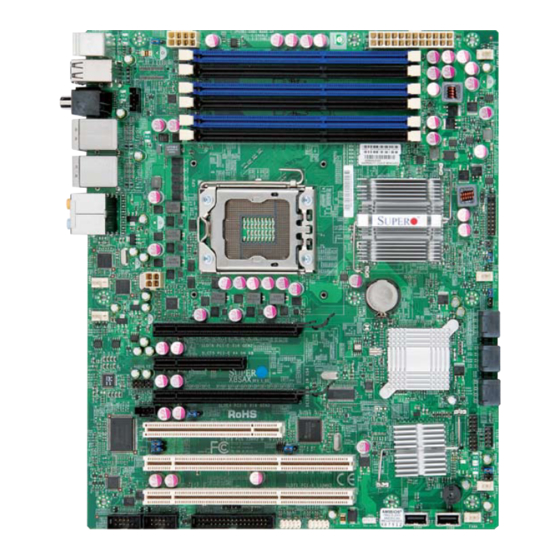
Chapter 1: Introduction Chapter 1 Introduction Overview Checklist Thank you for purchasing your computer motherboard from an acknowledged leader in the industry. Supermicro boards are designed with the utmost attention to detail to provide you with the highest standards in quality and performance. Please check that the following items have all been included with your motherboard. - Page 10 X8SAX/C7X58 User’s Manual X8SAX Image Note: All graphics shown in this manual were based upon the latest PCB Revision available at the time of publishing of the manual. The motherboard you've received may or may not look exactly the same as the graphics shown in this manual.
-
Page 11: Motherboard Layout
Chapter 1: Introduction Motherboard Layout JPUSB1 JPW1 JPW2 DIMM3A Fan1 - CPU DIMM3B DIMM2A DIMM2B DIMM1A DIMM1B X8SAX Intel North Bridge LAN CTRL Fan6 LAN CTRL Fan2 JPW3 Battery Fan5 Slot6 PCI-E x16 Gen2 JBT1 Intel ICH10R BIOS Slot5 PCI-E x4 in x8 Gen1 South Bridge Audio FP Audio CTRL... -
Page 12: Default Setting
X8SAX/C7X58 User’s Manual X8SAX Quick Reference JPUSB1 JPW1 JPW2 DIMM3A Fan1 - CPU DIMM3B DIMM2A DIMM2B DIMM1A DIMM1B X8SAX Intel North Bridge LAN CTRL Fan6 LAN CTRL Fan2 JPW3 Battery Fan5 Slot6 PCI-E x16 Gen2 JBT1 Intel ICH10R BIOS Slot5 PCI-E x4 in x8 Gen1 South Bridge Audio FP Audio CTRL... - Page 13 Chapter 1: Introduction Connector Label Description 1394a_1/2 #25, 26 IEEE 1394a connection headers Audio FP Front panel audio header (HD) Audio (BP) High Definition Audio (7.1) header Battery Onboard battery (B1) CD-In Audio CD Input header COM1/COM2 #22, 21 COM1/2 Serial connection headers Fans 1~6 #8, 47, 36, 35, System/CPU fan headers (Fan 1: CPU fan)
-
Page 14: Motherboard Features
X8SAX/C7X58 User’s Manual Motherboard Features ® Core™ i7 / i7 Extreme Edition, and Intel® Xeon® 5500/3500 series • Single Intel processors in an LGA1366 socket Memory • Six 240-pin, DDR3 SDRAM DIMM sockets with support for unbuffered ECC (if supported by CPU) or non ECC 1333/1066/800 MHz memory. •... - Page 15 Chapter 1: Introduction Network Connections • Two Intel 82574L Gigabit (10/100/1000 Mb/s) Ethernet Controllers with two Gigabit LAN ports • Two (2) RJ-45 backplane connectors with Link and Activity LEDs built-in I/O Devices SATA Connections • Six (6) SATA ports supported by the Intel ICH10R SATA Controller •...
- Page 16 X8SAX/C7X58 User’s Manual PC Health Monitoring CPU Monitoring • Onboard voltage monitors for CPU core, Memory Voltage, Chipset Voltage, +1.8V, +3.3V, +3.3V standby, +5V, +5V, Standby, VBat and ±12V • CPU 6-Phase-switching voltage regulator • CPU/System overheat LED and control •...
- Page 17 Chapter 1: Introduction Notes...
- Page 18 X8SAX/C7X58 User’s Manual X8SAX / C7X58 Block Diagram DIMM_CH1 Intersil Intel DIMM_CH2 VRD 11.1 DIMM_CH3 QPI: Up to 6.40 GT/s DDR3:1600XMP/1333/1066/800 (1600XMP is supported on the C7X58 motherboard only, see page 3-3 for more information) PCIE_x16 PCI_E x16 Slot Intel PCIE_x16 PCI_E x16 Slot North Bridge...
-
Page 19: Chipset Overview
Chapter 1: Introduction Chipset Overview Built upon the functionality and the capability of the Intel X58 Express chipset, the X8SAX/C7X58 motherboard provides the performance and feature set required for dual-processor systems with configuration options optimized for intensive ap- plication and high-end workstation platforms. The main architecture of the X8SAX/C7X58 consists of an LGA 1366 processor socket, the Intel X58 Express North Bridge chipset, the ICH10R South Bridge, and the PXH/V IO Bridge. -
Page 20: Pc Health Monitoring
X8SAX/C7X58 User’s Manual PC Health Monitoring This section describes the PC health monitoring features of the X8SAX/C7X58. The motherboard has an onboard System Hardware Monitor chip that supports PC health monitoring. Recovery from AC Power Loss BIOS provides a setting for you to determine how the system will respond when AC power is lost and then restored to the system. -
Page 21: Slow Blinking Led For Suspend-State Indicator
Chapter 1: Introduction Slow Blinking LED for Suspend-State Indicator When the CPU goes into a suspend state, the chassis power LED will start blink- ing to indicate that the CPU is in the suspend mode. When the user presses any key, the CPU will wake-up and the LED indicator will automatically stop blinking and remain on. -
Page 22: Super I/O
X8SAX/C7X58 User’s Manual Super I/O The disk drive adapter functions of the Super I/O chip include a floppy disk drive controller that is compatible with industry standard 82077/765, a data separator, write pre-compensation circuitry, decode logic, data rate selection, a clock genera- tor, drive interface control logic and interrupt and DMA logic. -
Page 23: Chapter 2 Installation
Chapter 2: Installation Chapter 2 Installation Static-Sensitive Devices Electrostatic-Discharge (ESD) can damage electronic com ponents. To prevent dam- age to your system board, it is important to handle it very carefully. The following measures are generally sufficient to protect your equipment from ESD. Precautions •... -
Page 24: Processor And Heatsink Installation
X8SAX/C7X58 User's Manual Processor and Heatsink Installation When handling the processor package, avoid placing direct pressure on the label area of the fan. Notes: Always connect the power cord last and always remove it before adding, re- moving or changing any hardware components. Make sure that you install the processor into the CPU socket before you install the CPU heatsink. - Page 25 Chapter 2: Installation After removing the plastic cap, using your thumb and the index finger, hold the CPU at the north and south center edges. Align the CPU key, the semi- circle cutout, against the socket key, the notch below the gold color dot on the side of the CPU Socket socket.
-
Page 26: Installing An Active Fan Cpu Heatsink
X8SAX/C7X58 User's Manual Installing an Active Fan CPU Heatsink 1. Locate the CPU Fan power con- nector on the motherboard. (Refer to Thermal Grease the layout on the right for the CPU Fan location.) 2. Position the heatsink so that the heatsink fan wires are closest to the CPU fan power connector and are not interfered with other components. -
Page 27: Removing The Heatsink
Chapter 2: Installation 7. Align the four heatsink fasten- ers with the mounting holes on the motherboard. Gently push the pairs of diagonal fasteners (#1 & #2, and #3 & #4) into the mounting holes until you hear a click. (Note: Make sure to orient each fastener so that the narrow end Narrow end of the groove of the groove is pointing outward.) -
Page 28: Installing A Passive Cpu Heatsink
X8SAX/C7X58 User's Manual Installing a Passive CPU Heatsink Note: Passive CPU Heatsinks that have been purchased from Supermicro will include the optional heatsink bracket. Heatsinks pur- chased elsewhere may not include this bracket, but is available sepa- rately from Supermicro. Heatsink Mounting Holes (4) on the motherboard. - Page 29 Chapter 2: Installation Screw in two diagonal screws (i.e., the #1 and the #2 screws) until secure. However, leave each loosely tightened until all four screws are in place. Finish the installation by fully tightening all four screws. Do Screw#1 Screw#2 not over-tighten to avoid pos- sible damage to the CPU.
-
Page 30: Mounting The Motherboard Into The Chassis
X8SAX/C7X58 User's Manual Mounting the Motherboard into the Chassis All motherboards have standard mounting holes to fit different types of chassis. Make sure that the locations of all mounting holes for the motherboard and the chas- sis match. Although a chassis may have both plastic and metal mounting fasteners, metal ones are highly recommended because they ground the motherboard to the chassis. -
Page 31: Installing And Removing The Memory Modules
Chapter 2: Installation Installing and Removing the Memory Modules Note: Check the Supermicro web site for recommended memory modules. CAUTION Exercise extreme care when installing or removing DIMM modules to prevent any possible damage. Press down the release tabs Installing & Removing DIMMs Insert the desired number of DIMMs into the memory slots, starting with DIMM1A. -
Page 32: Memory Support
X8SAX/C7X58 User's Manual Memory Support DIMM Module Population Configuration Maximum Memory Possible Single Rank UDIMMs - 12GB (6x 2GB DIMMs), Dual Rank UDIMMs - 24GB (6x 4GB DIMMs). See Note 5 on the next page for XMP memory support (C7X58 only). JPUSB1 JPW1 JPW2... - Page 33 Chapter 2: Installation Note 4: For Microsoft Windows users: Microsoft implemented a design change in Windows XP with Service Pack 2 (SP2) and Windows Vista. This change is specific to the Physical Address Extension (PAE) mode behavior which improves driver compatibility. For more information, please read the following article at Microsoft’s Knowledge Base website at: http://support.microsoft.
-
Page 34: Connectors/Io Ports
X8SAX/C7X58 User's Manual Connectors/IO Ports The I/O ports are color coded in conformance with the PC 99 specification. See the figure below for the colors and locations of the various I/O ports. Back Panel Connectors and IO Ports JPUSB1 JPW2 JPW1 DIMM3A Fan5... -
Page 35: Atx Ps/2 Keyboard And Ps/2 Mouse Ports
Chapter 2: Installation ATX PS/2 Keyboard and PS/2 PS/2 Keyboard/Mouse Pin Mouse Ports Definitions PS2 Keyboard PS2 Mouse The ATX PS/2 keyboard and PS/2 Pin# Definition Pin# Definition mouse are located next to the Back KB Data Mouse Data Panel USB Ports 1~2 on the moth- No Connection No Connection erboard. -
Page 36: Universal Serial Bus (Usb)
X8SAX/C7X58 User's Manual Universal Serial Bus (USB) Back Panel USB 0~3, 4/5, 6/7 Pin Definitions Eight Universal Serial Bus ports (USB Pin# Definition Pin# Definition 0~3, USB 4/5, USB 6/7) are located on the I/O back panel. USB Ports 4/5 are USB_PN1 USB_PN0 located below LAN Port1 port. -
Page 37: Ethernet Ports
Chapter 2: Installation Ethernet Ports LAN Ports Pin Definition Two Ethernet ports are located at on Pin# Definition the IO backplane above the backpanel P2V5SB SGND USB ports. These ports accept RJ45 TD0+ Act LED type cables. (Note: Please refer to the TD0- P3V3SB LED Indicator Section for LAN LED... -
Page 38: High Definition Audio (Hda)
X8SAX/C7X58 User's Manual High Definition Audio (HDA) The X8SAX/C7X58 features a 7.1+2 Channel Orange: High Definition Audio (HDA) codec that pro- Blue: Line-In CEN/LFE vides 10 DAC channels, simultaneously sup- Black: Back Green: Front porting 7.1 sound playback and two channels Surround of independent stereo sound output (multiple Grey: Side Pink: Mic-In Surround... -
Page 39: Front Panel Audio Control
Chapter 2: Installation Front Panel Audio Control HD Front Panel Audio Pin Definitions When front panel headphones are plugged in, Pin# Signal the back panel audio output is disabled. This is MIC, Left Channel done through the FP Audio header (Audio FP). Ground If the front panel interface card is not connected MIC, Right Channel... -
Page 40: Serial Ports
X8SAX/C7X58 User's Manual Serial Ports Serial Port Pin Definitions (COM1/COM2) Two COM Port headers are located Pin # Definition Pin # Definition on the motherboard. See the table on the right for pin definitions. Ground Serial ATA Ports S i x Se rial AT A ( S A T A ) p o r t s (SATA0~SATA5) are located next SATA Port to the ICH10R on the motherboard. -
Page 41: Front Control Panel
Chapter 2: Installation Front Control Panel JF1 contains header pins for various buttons and indicators that are normally lo- cated on a control panel at the front of the chassis. These connectors are designed specifically for use with Supermicro server chassis. See the figure below for the descriptions of the various control panel buttons and LED indicators. -
Page 42: Front Control Panel Pin Definitions
X8SAX/C7X58 User's Manual Front Control Panel Pin Definitions NMI Button NMI Button Pin Definitions (JF1) The non-maskable interrupt button Pin# Definition header is located on pins 19 and 20 Control of JF1. Refer to the table on the right Ground for pin definitions. Power LED Power LED Pin Definitions (JF1) The Power LED connection is located Pin#... -
Page 43: Hdd Led
Chapter 2: Installation HDD LED The HDD LED connection is located HDD LED Pin Definitions (JF1) on pins 13 and 14 of JF1. Attach a Pin# Definition hard drive LED cable here to display disk activity detected on the mother- HD Active board's built-in disk controllers (for any hard drive activities on the sys- tem, including Serial ATA and IDE). -
Page 44: Overheat (Oh)/Fan Fail Led
X8SAX/C7X58 User's Manual Overheat (OH)/Fan Fail LED OH/Fan Fail LED Pin Definitions (JF1) Connect an LED cable to the OH/ Pin# Definition Fan Fail connection on pins 7 and 8 of JF1 to provide advanced warnings Ground for chassis overheat or fan failure. OH/Fan Fail Indicator Refer to the table on the right for pin Status... -
Page 45: Reset Button
Chapter 2: Installation Reset Button Reset Button The Reset Button connection is located Pin Definitions (JF1) on pins 3 and 4 of JF1. Attach it to a Pin# Definition hardware reset switch on the computer Reset case to reset the system. Refer to the Ground table on the right for pin definitions. -
Page 46: Connecting Cables
X8SAX/C7X58 User's Manual Connecting Cables This section provides brief descriptions and pin-out definitions for onboard headers and connectors. Be sure to use the correct cable for each header or connector. • For information on Backpanel USB and Front Panel USB ports, refer to Page 2-9. -
Page 47: Fan Headers
Chapter 2: Installation Fan Headers The X8SAX/C7X58 has six fan headers Fan Header (Fan1 ~ Fan6). Fans 2~6 are system Pin Definitions cooling fans. Fan 1 is used as a CPU Pin# Definition fan. These fans are 4-pin fan headers. Ground (Black) However, Pins 1-3 of the fan headers are 2.5A/+16V (Red) -
Page 48: Internal Buzzer
X8SAX/C7X58 User's Manual Internal Buzzer Internal Buzzer (SP1) Pin Definition The Internal Buzzer (SP1) can be Pin# Definitions used to provide audible indications Pin 1 Pos. (+) Beep In for various beep codes. See the table Pin 2 Neg. (-) Alarm on the right for pin definitions. -
Page 49: Overheat/Fan Fail Led (Joh1 )
Chapter 2: Installation Overheat/Fan Fail LED (JOH1 Overheat LED Pin Definitions The JOH1 header is used to connect Pin# Definition an LED to provide warnings of chas- 5vDC sis overheat. This LED will also blink OH Active to indicate a fan failure. Refer to the table on right for pin definitions. -
Page 50: Power Supply I 2 C Connector
X8SAX/C7X58 User's Manual Power Supply I C Connector PWR Supply I Pin Definitions Power Supply (I C) Connector moni- Pin# Definition tors the status of the power supply, Clock fan and system temperature. See the Data table on the right for pin definitions. PWR Fail Ground Onboard Power LED... -
Page 51: 1394A_1/1394A_2 Connections
Chapter 2: Installation 1394a_1/1394a_2 Connections 1394a_1 Pin Definitions 1394a_1 and 1394a_2 provide the Pin# Defin. Pin# Defin IEEE 1394 connections on the moth- PTPA0+ PTPA0- erboard. See the tables on the right for pin definitions. PTPB0+ PTPB0- PWR 1394 PWR 1394 J1394a_2 Pin Definitions Pin#... -
Page 52: Wake-On-Ring
X8SAX/C7X58 User's Manual Wake-On-Ring Wake-On-Ring Pin Definitions The Wake-On-Ring header is des- (JWOR) ignated JWOR. This function allows Pin# Definition your computer to wake up when Ground receiving an incoming call to the Wake-up modem when in the suspend state. See the table on the right for pin definitions. -
Page 53: Jumper Settings
Chapter 2: Installation Jumper Settings Explanation of Jumpers To modify the operation of the mother- board, jumpers can be used to choose between optional settings. Jumpers cre- ate shorts between two pins to change the function of the connector. Pin 1 is identified with a square solder pad on the printed circuit board. -
Page 54: Cmos Clear
X8SAX/C7X58 User's Manual CMOS Clear JBT1 is used to clear CMOS. Instead of pins, this "jumper" consists of contact pads to prevent accidental clearing of CMOS. To clear CMOS, use a metal object such as a small screwdriver to touch both pads at the same time to short the connection. Always remove the AC power cord from the system before clearing CMOS. -
Page 55: Smb To Pci-X/Pci-E Slots Speeds
Chapter 2: Installation SMB to PCI-X/PCI-E Slots Speeds SMBus to PCI-X/PCI-Exp Slots Use Jumper JI C1 to connect the System Jumper Settings Management Bus to the PCI slots, and Jumper Setting Definition Jumper JI C2, to the PCI-Exp. slots in Pins 1-2 Enabled order to improve power management... -
Page 56: Audio Enable
X8SAX/C7X58 User's Manual Audio Enable Audio Enable (JPAC) JPAC enables or disables the onboard audio Pin# Definition connections. See the table on the right Enabled (default) for jumper settings. The default setting is Disabled Enabled. USB Wake-Up Use JPUSB jumpers to "wake-up" your sys- tem by pressing a key on a USB keyboard or JPUSB1 (BackPanel USB Wake-up) -
Page 57: Onboard Indicators
Chapter 2: Installation Onboard Indicators GLAN Link/Speed LED Indicator Lan Port LEDs LED Color Definition Two LAN ports are located on the I/O No Connection or 10 Mbps Backplane. Each LAN port has two LEDs. Green (On) 100 Mbps The yellow GLAN Activity LED (see be- Amber (On) 1 Gbps low) indicates activity, while the GLAN... -
Page 58: Serial Ata And Floppy Drive Connections
X8SAX/C7X58 User's Manual Serial ATA and Floppy Drive Connections Note the following conditions when connecting the Serial ATA and floppy disk drive cables: • Be sure to use the correct cable for each connector. Refer to Page 1-1 for cables that came with your shipment. -
Page 59: Floppy Connector
Chapter 2: Installation Floppy Connector Floppy Drive Connector Pin Definitions The floppy connector is located near Pin# Definition Pin # Definition the PCI-X Slot 1 on the motherboard. Ground FDHDIN See the table on the right for pin Ground Reserved definitions. FDEDIN Ground Index... - Page 60 X8SAX/C7X58 User's Manual Notes 2-38...
-
Page 61: Chapter 3 Troubleshooting
Chapter 3: Troubleshooting Chapter 3 Troubleshooting Troubleshooting Procedures Use the following procedures to troubleshoot your system. If you have followed all of the procedures below and still need assistance, refer to the ‘Technical Support Procedures’ and/or ‘Returning Merchandise for Service’ section(s) in this chapter. Always disconnect the AC power cord before adding, changing or installing any hardware components. -
Page 62: Memory Errors
X8SAX/C7X58 User's Manual 2. Use the speaker to determine if any beep codes exist. (Refer to Appendix A for details on beep codes.) 3. Remove all memory modules and turn on the system. (If the alarm is on, check the specs of memory modules, reset the memory or try a different one.) Memory Errors 1. -
Page 63: Frequently Asked Questions
Chapter 3: Troubleshooting Note: Not all BIOS can be flashed. Some cannot be flashed; it depends on the modifications to the boot block code. 3. If you've followed the instructions above to troubleshoot your system, and still cannot resolve the problem, then contact Supermicro's technical support and provide them with the following information: •... - Page 64 X8SAX/C7X58 User's Manual Question: When I plug in my 1600 MHz XMP DDR3 memory into the X8SAX or C7X58 motherboard, it only shows that it's running at 1333MHz or 1066 MHz. How can I make it work at 1600MHz? Answer: The X8SAX motherboard does not support 1600MHz XMP memory. Therefore, it will only support up to 1066/1333MHz.
-
Page 65: Returning Merchandise For Service
Chapter 3: Troubleshooting When the BIOS flashing screen is completed, the system will reboot and will show “Press F1 or F2”. At this point, you will need to load the BIOS defaults. Press <F1> to go to the BIOS setup screen, and press <F9> to load the default settings. - Page 66 X8SAX/C7X58 User's Manual Notes...
-
Page 67: Chapter 4 Bios
Chapter 4: AMI BIOS Chapter 4 BIOS Introduction This chapter describes the AMI BIOS Setup Utility for the X8SAX/C7X58. The AMI ROM BIOS is stored in a Flash EEPROM and can be easily updated. This chapter describes the basic navigation of the AMI BIOS Setup Utility setup screens. Starting BIOS Setup Utility To enter the AMI BIOS Setup Utility screens, press the <Delete>... -
Page 68: Starting The Setup Utility
X8SAX/C7X58 User’s Manual Starting the Setup Utility Normally, the only visible POST (Power On Self Test) routine is the memory test. As the memory is being tested, press the <Delete> key to enter the main menu of the AMI BIOS Setup Utility. From the main menu, you can access the other setup screens. - Page 69 Chapter 4: AMI BIOS Processor The AMI BIOS will automatically display the status of processor as shown below: Speed Physical Count Logical Count System Memory This displays the size of memory available in the system: Populated Size Available Size...
-
Page 70: 4-3 Advanced Setup Configurations
X8SAX/C7X58 User’s Manual 4-3 Advanced Setup Configurations Use the arrow keys to select Boot Setup and hit <Enter> to access the submenu items: BOOT Feature Quick Boot Select Enabled, to skip certain tests during POST to reduce the time needed for system boot. The options are Enabled and Disabled. Quiet Boot This option allows the user to choose between POST messages and the OEM logo. - Page 71 Chapter 4: AMI BIOS Wait For 'F1' If Error Select Enabled to force the system to wait until the 'F1' key is pressed if an error occurs. The options are Disabled and Enabled. Hit 'Del' Message Display Select Enabled to display: "Press DEL to run Setup" during POST. The options are Enabled and Disabled.
- Page 72 X8SAX/C7X58 User’s Manual Ratio CMOS Setting This option allows the user to set the ratio between the CPU Core Clock and the FSB Frequency. (Note: if an invalid ratio is entered, the AMI BIOS will restore the setting to the previous state.) The default setting depends on what type of CPU is installed.
- Page 73 Chapter 4: AMI BIOS and where it cannot, thus preventing a worm or a virus from flooding illegal codes to overwhelm the processor or damage the system during an attack. The default is Enabled. (Refer to Intel and Microsoft Web Sites for more information.) Simultaneous Multi-Threading (Available when supported by the CPU) Set to Enabled to use the Hyper-Threading Technology, which will result in increased CPU performance.
- Page 74 X8SAX/C7X58 User’s Manual C1E Support Select Enabled to use the "Enhanced Halt State" feature. C1E significantly reduces the CPU's power consumption by reducing the CPU's clock cycle and voltage during a "Halt State." The options are Disabled and Enabled. C-STATE Tech If enabled, C-State is set by the system automatically to either C2, C3 or C4 state.
-
Page 75: Advanced Chipset Control
Chapter 4: AMI BIOS Advanced Chipset Control The items included in the Advanced Settings submenu are listed below: QPI and IMC Configuration QuickPath Interconnect (QPI) is the connection between the CPU and the motherboard's I/O hub. Use this feature to modify speed and power manage- ment settings. - Page 76 X8SAX/C7X58 User’s Manual updated as well. Select Enabled to use Demand Scrubbing for ECC memory cor- rection. The options are Enabled and Disabled. Patrol Scrubbing Patrol Scrubbing is a process that allows the North Bridge to correct correctable memory errors detected on a memory module and send the correction to the re- questor (the original source).
- Page 77 Chapter 4: AMI BIOS 901~1200 (above-), 1201~1500 (above-), 1501~1800 (above-), 1801~2100 (above-), 2101~2400 (above-), 2401~2700 (above-), and 2701~3000 (above-) the sea level. DIMM Pitch Use this feature to specify the distance of physical space between each DIMM module. Each step is in 1/1000 of an inch. The default is [400]. Press "+" or "-" on your keyboard to change this value.
- Page 78 X8SAX/C7X58 User’s Manual Active State Power Management Select Enabled to start Active-State Power Management for signal transactions between L0 and L1 Links on the PCI Express Bus. This maximizes power-saving and transaction speed. The options are Enabled and Disabled. USB Functions This feature allows the user to decide the number of onboard USB ports to be en- abled.
- Page 79 Chapter 4: AMI BIOS IDE / Floppy Configuration When this submenu is selected, the AMI BIOS automatically detects the presence of the IDE Devices and displays the following items: Floppy A This feature allows the user to select the type of floppy drive connected to the sys- tem.
- Page 80 X8SAX/C7X58 User’s Manual activate the following submenu screen for detailed options of these items. Set the correct configurations accordingly. The items included in the submenu are: Type Select the type of device connected to the system. The options are Not Installed, Auto, CD/DVD and ARMD.
- Page 81 Chapter 4: AMI BIOS DMA Mode Select Auto to allow the BIOS to automatically detect IDE DMA mode when the IDE disk drive support cannot be determined. Select SWDMA0 to allow the BIOS to use Single Word DMA mode 0. It has a data transfer rate of 2.1 MBs.
- Page 82 X8SAX/C7X58 User’s Manual PCI/PnP Configuration This feature allows the user to set the PCI/PnP configurations for the following items: Clear NVRAM This feature clears the NVRAM during system boot. The options are No and Yes. Plug & Play OS Select Yes to allow the OS to configure Plug & Play devices. (This is not required for system boot if your system has an OS that supports Plug &...
- Page 83 Chapter 4: AMI BIOS Super IO Device Configuration Serial Port1 Address/ Serial Port2 Address This option specifies the base I/O port address and the Interrupt Request address of Serial Port 1 and Serial Port 2. Select Disabled to prevent the serial port from accessing any system resources.
-
Page 84: Hardware Health Configuration
X8SAX/C7X58 User’s Manual Redirection After BIOS POST Select Disabled to turn off Console Redirection after Power-On Self-Test (POST). Select Always to keep Console Redirection active all the time after POST. (Note: This setting may not be supported by some operating systems.) Select Boot Loader to keep Console Redirection active during POST and Boot Loader. - Page 85 Chapter 4: AMI BIOS The Early Alarm Setting: Select this setting if you want the CPU overheat alarm (including the LED and the buzzer) to be triggered as soon as the CPU temperature reaches the CPU overheat threshold as predefined by the CPU manufacturer.
- Page 86 X8SAX/C7X58 User’s Manual by a unique temperature information that the motherboard can read. This ‘Temperature Threshold’ or ‘Temperature Tolerance’ has been assigned at the factory and is the baseline by which the motherboard takes action during different CPU temperature conditions (i.e., by increasing CPU Fan speed, triggering the Overheat Alarm, etc).
- Page 87 Chapter 4: AMI BIOS ACPI Configuration Use this feature to configure Advanced Configuration and Power Interface (ACPI) power management settings for your system. USB Device Wake-Up This feature is used to awaken the system from Standby mode by a Universal Serial Bus (USB) device (such as, a USB mouse or USB keyboard). The options are Enabled and Disabled.
-
Page 88: Security Settings
X8SAX/C7X58 User’s Manual Clear event log This option clears the Event Log memory of all messages. The options are OK and Cancel. Security Settings The AMI BIOS provides a Supervisor and a User password. If you use both pass- words, the Supervisor password must be set first. Supervisor Password This item indicates if a supervisor password has been entered for the system. -
Page 89: 4-5 Boot Configuration
Chapter 4: AMI BIOS Change User Password Select this feature and press <Enter> to access the submenu , and then type in a new User Password. Clear User Password (Available only if User Password has been set) Password Check Available options are Setup and Always. Boot Sector Virus Protection When Enabled, the AMI BIOS displays a warning when any program (or virus) is- sues a Disk Format command or attempts to write to the boot sector of the hard... -
Page 90: Exit Options
X8SAX/C7X58 User’s Manual Removable Drives This feature allows the user to specify the boot sequence from available Removable Drives. The settings are 1st boot device, 2nd boot device, and Disabled. • 1st Drive • 2nd boot device - [USB: XXXXXXXXX] Exit Options Select the Exit tab from the AMI BIOS Setup Utility screen to enter the Exit BIOS Setup screen. - Page 91 Chapter 4: AMI BIOS Load Optimal Defaults To set this feature, select Load Optimal Defaults from the Exit menu and press <Enter>. Then, select OK to allow the AMI BIOS to automatically load Optimal De- faults to the BIOS Settings. The Optimal settings are designed for maximum system performance, but may not work best for all computer applications.
- Page 92 X8SAX/C7X58 User’s Manual Notes 4-26...
-
Page 93: Appendix A Post Error Beep Codes
Appendix A: POST Error Beep Codes Appendix A POST Error Beep Codes This section lists POST (Power On Self Test) error beep codes for the AMI BIOS. POST error beep codes are divided into two categories: recoverable and terminal. This section lists Beep Codes for recoverable POST errors. Recoverable POST Error Beep Codes When a recoverable type of error occurs during POST, BIOS will display a POST code that describes the problem. - Page 94 X8SAX/C7X58 User's Manual Notes...
-
Page 95: Appendix B Software Installation Instructions
Appendix B: Software Installation Instructions Appendix B Software Installation Instructions B-1 Installing Drivers After you've installed the Windows Operating System, a screen as shown below will appear. You are ready to install software programs and drivers that have not yet been installed. -
Page 96: Configuring Supero Doctor Iii
X8SAX/C7X58 User's Manual B-2 Configuring Supero Doctor III The Supero Doctor III program is a Web-base management tool that supports remote management capability. It includes Remote and Local Management tools. The local management is called the SD III Client. The Supero Doctor III program included on the CDROM that came with your motherboard allows you to monitor the environment and operations of your system. - Page 97 Appendix B: Software Installation Instructions Supero Doctor III Interface Display Screen-II (Remote Control) Note: SD III Software Revision 1.0 can be downloaded from our Web site at: ftp://ftp.supermicro.com/utility/Supero_Doctor_III/. You can also download SDIII User's Guide at: http://www.supermicro.com/PRODUCT/ Manuals/SDIII/UserGuide.pdf. For Linux, we will still recommend that you use Supero Doctor II.
- Page 98 X8SAX/C7X58 User's Manual Notes...
-
Page 99: Appendix C - Bios Recovery
Appendix D: BIOS Recovery Appendix C - BIOS Recovery The recovery procedure described in this section is to be used only when advised by your Supermicro Technical Support representative, or in cases of emergencies where the system no longer can boot due to a corrupted BIOS. DO NOT re-program (re-flash) the BIOS if your system is running properly. -
Page 100: Recovery Process From An Ide/Sata Atapi Disc Driv
X8SAX/C7X58 User's Manual When the Boot Sector Recovery Process is complete, the system will reboot automatically and you will see a checksum error on your screen. Part 2 - BIOS Reprogramming (Re-Flashing) After completing the Boot Sector Recovery Process, you will need to reprogram (“re-flash”) the proper BIOS binary file again into the BIOS ROM in order to have the correct BIOS file loaded by the system. - Page 101 (Disclaimer) The products sold by Supermicro are not intended for and will not be used in life support systems, medical equipment, nuclear facilities or systems, aircraft, aircraft devices, aircraft/emergency communication devices or other critical systems whose failure to perform be reasonably expected to result in significant injury or loss of life or catastrophic property damage.
Need help?
Do you have a question about the Super X8SAX and is the answer not in the manual?
Questions and answers