Table of Contents
Advertisement
Advertisement
Table of Contents

Related Manuals for Supero C7Q67


Summary of Contents for Supero C7Q67
- Page 1 C7Q67 USER’S MANUAL Revision 1.0...
- Page 2 The information in this User’s Manual has been carefully reviewed and is believed to be accurate. The vendor assumes no responsibility for any inaccuracies that may be contained in this document, makes no commitment to update or to keep current the information in this manual, or to notify any person or organization of the updates.
-
Page 3: About This Motherboard
PC users. It provides information for the installation and use of the C7Q67 motherboard. About This Motherboard C7Q67 supports a single 2nd generation Intel® Core™ i7/i5/i3 DT processor in an LGA 1155 socket. With the Intel® Q67 Express chipset built in, the C7Q67 motherboard offers substantial enhancement in system performance and storage capability for high performance system platforms in a sleek package. -
Page 4: Conventions Used In The Manual
C7Q67 User’s Manual Conventions Used in the Manual: Special attention should be given to the following symbols for proper installation and to prevent damage done to the components or injury to yourself: Danger/Caution: Instructions to be strictly followed to prevent catastrophic... -
Page 5: Contacting Supermicro
Contacting Supermicro Contacting Supermicro Headquarters Address: Super Micro Computer, Inc. 980 Rock Ave. San Jose, CA 95131 U.S.A. Tel: +1 (408) 503-8000 Fax: +1 (408) 503-8008 Email: marketing@supermicro.com (General Information) support@supermicro.com (Technical Support) Web Site: www.supermicro.com Europe Address: Super Micro Computer B.V. Het Sterrenbeeld 28, 5215 ML 's-Hertogenbosch, The Netherlands Tel:... -
Page 6: Table Of Contents
C7Q67 User’s Manual Table of Contents Preface About This Motherboard ....................iii Manual Organization ..................... iii Conventions Used in the Manual: .................iv Contacting Supermicro ....................v Chapter 1 Introduction Overview ......................1-1 Checklist ......................1-1 Motherboard Features ..................1-6 Chipset Overview ................... 1-9 Intel Q67 Express Chipset Features ............... - Page 7 Table of Contents Location of Mounting Holes ................2-11 Installing the Motherboard ................2-12 Connectors/IO Ports ..................2-13 Backplane I/O Panel ..................2-13 ATX PS/2 Keyboard/Mouse Ports ............2-14 Universal Serial Bus (USB) ..............2-15 Ethernet Ports ..................2-16 (Back_Panel) High Definition Audio (HD Audio) ........2-16 HD Audio .......................
- Page 8 C7Q67 User’s Manual LAN 1/LAN 2 LEDs .................. 2-32 Onboard Power LED ................2-32 SATA Connections ..................2-33 SATA Connections (I-SATA0~I-SATA5) ............ 2-33 Chapter 3 Troubleshooting Troubleshooting Procedures ................3-1 Before Power On .................... 3-1 No Power ......................3-1 No Video ......................3-2 Memory Errors ....................
- Page 9 Table of Contents VFC ......................4-5 Processor & Clock Options ................4-5 Hardware Prefetcher (Available when supported by the CPU) ....4-5 Adjacent Cache Line Prefetch (Available when supported by the CPU) ... 4-6 Intel® Virtualization Technology (Available when supported by the CPU) 4-6 Execute-Disable Bit Capability (Available when supported by the OS and the CPU) .....................
- Page 10 C7Q67 User’s Manual On Board Chip Configuration ..............4-10 USB 3.0 Legacy Support ................. 4-10 XHCI Hand-off ..................4-10 IDE/SATA Configuration ................4-10 SATA Mode ....................4-10 IDE Mode ....................4-10 Serial-ATA Controller 0~1 ................. 4-10 SATA Port0~Port5 ..................4-10 AHCI Mode ....................
- Page 11 Appendix A BIOS Error Beep Codes BIOS Error Beep Codes .................A-1 Appendix B Software Installation Instructions Installing Drivers ....................B-1 Configuring Supero Doctor III .................B-2 Appendix C BIOS Recovery Recovery Process from a USB Device/Drive (Recommended Method) ..C-1 Part 1: Boot Sector Recovery Process ............C-1 Part 2: BIOS Reprogramming (Re-Flashing) ..........C-2...
- Page 12 C7Q67 User’s Manual Notes...
-
Page 13: Chapter 1 Introduction
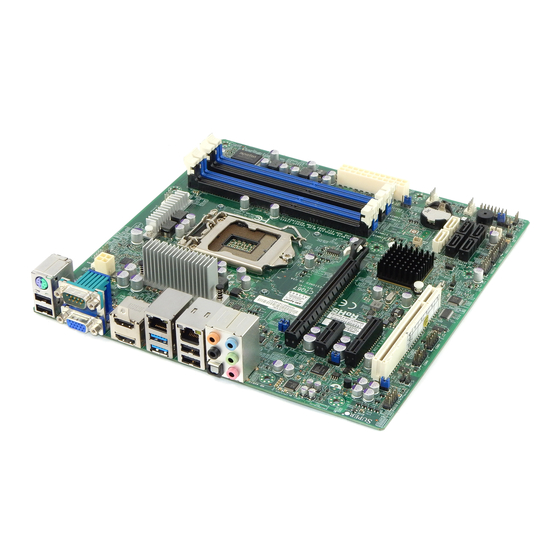
Chapter 1: Introduction Chapter 1 Introduction Overview Checklist Congratulations on purchasing your computer motherboard from an acknowledged leader in the industry. Supermicro boards are designed with the utmost attention to detail to provide you with the highest standards in quality and performance. Please check that the following items have all been included with your motherboard. - Page 14 C7Q67 User’s Manual C7Q67 Motherboard Image Note: All graphics shown in this manual were based upon the latest PCB Revision available at the time of publishing of the manual. The motherboard you've received may or may not look exactly the same as the graphics shown in this manual.
- Page 15 Chapter 1: Introduction C7Q67 Motherboard Layout Important Notes to the User • See Chapter 2 for detailed information on jumpers, I/O ports and JF1 front panel connections. • " " indicates the location of "Pin 1". • Jumpers not indicated are for testing only.
-
Page 16: Jumper Description
C7Q67 User’s Manual C7Q67 Quick Reference LAN 1 HDMI 1 KB/MOUSE HD AUDIO USB (3.0) 0/1 COM1 HDMI 2 USB 8/9 LAN 2 USB (3.0) 10/13 JPL2 SLOT4 SLOT7 Audio FP SLOT5 SLOT6 JHD AC1 JPAC1 JSPDIF_IN JPW2 JSPDIF_OUT FAN4... - Page 17 USB (2.0) 10/13, 8/9 Backpanel USB 2.0 Ports 10/13, 8/9 USB (3.0) 0/1 Backpanel USB 3.0 Ports 0/1 USB2/3, USB4/5, 11/12 Front Accessible USB Connections 2/3, 4/5, 11/12 C7Q67 LED Indicators Description Color/State Status LED1 Onboard Standby PWR LED Green: Solid on...
-
Page 18: Motherboard Features
C7Q67 User’s Manual Motherboard Features Single 2nd generation Intel Intel® Core™ i7/i5/i3 DT pro- cessor in an LGA1155 socket. Memory Four (4) SDRAM slots support up to 32 GB of DDR3 Unbuf- fered, Non-ECC 1333/1066 memory Supports dual-channel memory bus... - Page 19 Modulation) fan speed control Low noise fan speed control System Management PECI (Platform Environment Configuration Interface) 2.0 support System resource alert via Supero Doctor III SuperoDoctor III, Watch Dog, NMI Chassis Intrusion header and detection CD Utilities BIOS flash upgrade utility Drivers and software for Intel®...
-
Page 20: System Block Diagram
C7Q67 User’s Manual C7Q67 Block Diagram SVID VRM 12 PCIe2.0_x16 PCIe x16 SLOT #7 5.0GT/s INTEL LGA1155 DDR3 (CHA) DIMM1A (Blue) 4 UDIMM DIMM1B 1333/1066MHz DDR3 (CHB) DIMM2A (Blue) DIMM2B 1333/1066MHz x4 DMI x4 FDI 5GT/s 2.7 Gbps PCIe2.0_x1 GLAN1... -
Page 21: Chipset Overview
Chapter 1: Introduction Chipset Overview The C7Q67 supports a single 2nd generation Intel® Core i7/i5/i3 DT processor in the LGA 1155 Socket. Built upon the functionality and the capability of the Q67 Express chipset, the motherboard provides substantial enhancement to system performance and storage capability for high performance platforms in a sleek package. -
Page 22: Special Features
Note: To avoid possible system overheating, please be sure to provide adequate airflow to your system. System Resource Alert This feature is available when the system is used with Supero Doctor III in the Windows OS environment or used with Supero Doctor II in Linux. Supero 1-10... -
Page 23: Acpi Features
Chapter 1: Introduction Doctor is used to notify the user of certain system events. For example, you can also configure Supero Doctor to provide you with warnings when the system temperature, CPU temperatures, voltages and fan speeds go beyond predefined thresholds. -
Page 24: Super I/O
C7Q67 User’s Manual 2. To provide adequate power to SATA devices, please connect the SATA DOM PWR connector (JWF1) to the power supply. It is strongly recommended that you use a high quality power supply that meets ATX power supply Specification 2.02 or above. It must also be SSI compliant. (For more information, please refer to the web site at http://www.ssiforum.org/). -
Page 25: Chapter 2 Installation
Chapter 2: Installation Chapter 2 Installation Static-Sensitive Devices Electrostatic-Discharge (ESD) can damage electronic com ponents. To avoid dam- aging your system board, it is important to handle it very carefully. The following measures are generally sufficient to protect your equipment from ESD. Precautions •... -
Page 26: Processor And Heatsink Installation
C7Q67 User's Manual Processor and Heatsink Installation Warning: When handling the processor package, avoid placing direct pressure on the label area of the fan. Notes: Always connect the power cord last, and always remove it before add- ing, removing or changing any hardware components. Make sure that you install the processor into the CPU socket before you install the CPU heatsink. - Page 27 Chapter 2: Installation Gently lift the load lever to open the load plate. Remove the plastic cap. Use your thumb and your index finger to hold the CPU at the North center edge and the South center edge of the CPU. North Center Edge South Center Edge Align the CPU key that is the semi-circle cutouts against the socket keys.
- Page 28 C7Q67 User's Manual Do not rub the CPU against the surface or against any pins of the socket to avoid damaging the CPU or the socket.) With the CPU inside the socket, inspect the four corners of the CPU to make sure that the CPU is properly installed.
-
Page 29: Installing An Active Cpu Heatsink With Fan
Chapter 2: Installation Installing an Active CPU Heatsink with Fan Locate the CPU Fan power connec- tor on the motherboard. (Refer to the layout on the right for the CPU Fan location.) Position the heatsink so that the heatsink fan wires are closest to the CPU fan power connector and are Thermal Grease not interfered with other compo-... - Page 30 C7Q67 User's Manual Align the four heatsink fasten- ers with the mounting holes on the motherboard. Gently push the pairs of diagonal fasteners (#1 & #2, and #3 & #4) into the mounting holes until you hear a click. Also,...
-
Page 31: Removing The Heatsink
Chapter 2: Installation Removing the Heatsink Warning: We do not recommend that the CPU or the heatsink be removed. However, if you do need to remove the heatsink, please follow the instructions be- low to remove the heatsink and to prevent damage done to the CPU or other components. -
Page 32: Installing Ddr3 Memory
C7Q67 User's Manual Installing DDR3 Memory Note: Check the Supermicro website for recommended memory mod- ules. CAUTION Exercise extreme care when installing or removing DIMM modules to prevent any possible damage. DIMM Installation Insert the desired number of DIMMs into the memory slots, starting with DIMM1A (Slot A, Channel 1, see the next page for the location). -
Page 33: Memory Support
Chapter 2: Installation Memory Support The C7Q67 supports up to 32GB of Unbuffered (UDIMM) DDR3 Non-ECC 1333/1066 MHz in 4 memory slots. Populating these DIMM modules with a pair of memory modules of the same type and same size will result in interleaved memory, which will improve memory performance. - Page 34 C7Q67 User's Manual Possible System Memory Allocation & Availability System Device Size Physical Memory Remaining (-Available) (4 GB Total System Memory) Firmware Hub flash memory (System BIOS) 1 MB 3.99 Local APIC 4 KB 3.99 Area Reserved for the chipset 2 MB 3.99...
-
Page 35: Motherboard Installation
Chapter 2: Installation Motherboard Installation All motherboards have standard mounting holes to fit different types of chassis. Make sure that the locations of all the mounting holes for both motherboard and chassis match. Although a chassis may have both plastic and metal mounting fas- teners, metal ones are highly recommended because they ground the motherboard to the chassis. -
Page 36: Installing The Motherboard
C7Q67 User's Manual Installing the Motherboard Install the I/O shield into the back of the chassis. Locate the mounting holes on the motherboard. (See the previous page.) Locate the matching mounting holes on the chassis. Align the mounting holes on the motherboard against the mounting holes on the chassis. -
Page 37: Connectors/Io Ports
Chapter 2: Installation Connectors/IO Ports The I/O ports are color coded in conformance with the PC 99 specification. See the figure below for the colors and locations of the various I/O ports. Backplane I/O Panel HD Audio Backplane I/O Panel A. -
Page 38: Atx Ps/2 Keyboard/Mouse Ports
C7Q67 User's Manual ATX PS/2 Keyboard/Mouse PS/2 Keyboard/Mouse Pin Ports Definitions PS2 Keyboard PS2 Mouse The ATX PS/2 keyboard and Pin# Definition Pin# Definition PS/2 mouse are located next to KB Data Mouse Data the Back Panel USB Ports 13/10... -
Page 39: Universal Serial Bus (Usb)
Chapter 2: Installation Universal Serial Bus (USB) Four Universal Serial Bus 2.0 ports (8/9, 13/10) are located on the I/O back panel, in addition to two USB 3.0 Ports (0/1) that are located below LAN1. USB headers 2/3, 4/5 & 11/12 are used to provide front chassis access using USB cables (not included). -
Page 40: Ethernet Ports
C7Q67 User's Manual Ethernet Ports LAN Ports Pin Definition Two Gigabit Ethernet ports (LAN1/ Pin# Definition LAN2) are located next to the HD Au- P2V5SB SGND dio Connector on the I/O Backpanel to TD0+ Act LED provide network connections. These TD0- P3V3SB ports accept RJ45 type cables. -
Page 41: Front Accessible Audio Header
Chapter 2: Installation Front Accessible Audio Header 10-in Audio Pin Definitions A 10-pin Audio header is also Pin# Signal located on the motherboard. This Microphone_Left header allows you to use the on- Audio_Ground board sound for audio playback. Microphone_Right Connect an audio cable to the au- Audio_Detect dio header to use this feature. -
Page 42: Front Control Panel
C7Q67 User's Manual Front Control Panel JF1 contains header pins for various buttons and indicators that are normally located on a control panel at the front of the chassis. These connectors are designed spe- cifically for use with Supermicro chassis. See the figure below for the descriptions of the front control panel buttons and LED indicators. -
Page 43: Front Control Panel Pin Definitions
Chapter 2: Installation Front Control Panel Pin Definitions Power LED Power LED Pin Definitions (JF1) The Power LED connection is located Pin# Definition on pins 15 and 16 of JF1. Refer to the table on the right for pin definitions. Ground HDD LED The HDD LED connection is located HDD LED Pin Definitions (JF1) on pins 13 and 14 of JF1. -
Page 44: Nic1/Nic2 (Lan1/Lan2)
C7Q67 User's Manual NIC1/NIC2 (LAN1/LAN2) LAN1/LAN2 LED Pin Definitions (JF1) The NIC (Network Interface Controller) Pin# Definition LED connection for LAN port 1 is located 9/11 on pins 11 and 12 of JF1, and the LED 10/12 Ground connection for LAN Port 2 is on Pins 9 and 10. -
Page 45: Reset Button
Chapter 2: Installation Reset Button Reset Button The Reset Button connection is located Pin Definitions (JF1) on pins 3 and 4 of JF1. Attach it to a Pin# Definition hardware reset switch on the computer Reset case to reset the system. Refer to the Ground table on the right for pin definitions. -
Page 46: Connecting Cables
C7Q67 User's Manual Connecting Cables This section provides brief descriptions and pin-out definitions for onboard headers and connectors. Be sure to use the correct cable for each header or connector. For information on Backpanel USB and Front Panel USB ports, refer to Page 2-17. For Front Panel Audio, please refer to Page 2-19. -
Page 47: Fan Headers (Fan 1 ~ Fan 4)
Chapter 2: Installation Fan Headers (Fan 1 ~ Fan 4) Fan Header Pin Definitions The C7Q67 has four fan headers (Fan 1~Fan Pin# Definition 4). These fans are 4-pin fan headers. How- Ground (Black) ever, Pins 1-3 of the fan headers are backward 2.5A/+12V... -
Page 48: Internal Buzzer (Sp1)
C7Q67 User's Manual Internal Buzzer (SP1) Internal Buzzer Pin Definition The Internal Buzzer (SP1) can be Pin# Definitions used to provide audible indications for Pin 1 Pos. (+) Beep In various beep codes. See the table on Pin 2 Neg. (-) Alarm the right for pin definitions. -
Page 49: Onboard Power Led (Jled)
Chapter 2: Installation Onboard Power LED (JLED) Onboard PWR LED Pin Definitions An onboard Power LED header is lo- Pin# Definition cated at JLED. This Power LED header is connected to Front Control Panel No Connection located at JF1 to indicate the status of Connection to PWR system power. -
Page 50: Dom Pwr Connector (Jwf1)
C7Q67 User's Manual DOM PWR Connector (JWF1) DOM PWR Pin Definitions The Disk-On-Module (DOM) power Pin# Definition connector, located at JWF1, provides 5V (Gen1/Gen) power to a solid state Ground DOM storage device connected to one Ground of the SATA ports. See the table on the right for pin definitions. -
Page 51: Wake-On-Ring (Jwor)
Chapter 2: Installation Wake-On-Ring (JWOR) Wake-On-Ring Pin Definitions The Wake-On-Ring header is located Pin# Definition at JWOR. This function allows your Ground computer to wake up when receiving Wake-up an incoming call to the modem while in the suspend state. See the table on the right for pin definitions. -
Page 52: Jumper Settings
C7Q67 User's Manual Jumper Settings Explanation of Jumpers To modify the operation of the mother- board, jumpers can be used to choose between optional settings. Jumpers create shorts between two pins to change the function of the connector. Pin 1 is identified with a square solder pad on the printed circuit board. -
Page 53: Cmos Clear (Jbt1)
Chapter 2: Installation CMOS Clear (JBT1) JBT1 is used to clear the saved system setup stored in the CMOS chip. To clear the contents of the CMOS, completely shut down the system, remove the AC power cord and then short JBT1 with a jumper. Remove the jumper before powering on the system again. -
Page 54: Me Recovery Enable (Jpme1)
C7Q67 User's Manual ME Recovery Enable (JPME1) ME Recovery Close JPME1 to enable ME (Manufacture Jumper Settings Mode) Recovery. See the table on the right Settings Definition for jumper settings. Enabled Normal (Default) HD FP Audio/AC' 97 FP Audio Select... -
Page 55: Audio Enable (Jpac1)
Chapter 2: Installation Audio Enable (JPAC1) Audio Enable/Disable Jumper Settings JPAC1 allows you to enable or disable Both Jumpers Definition the onboard audio support. The default Pins 1-2 Enabled position is on pins 1 and 2 to enable on- Pins 2-3 Disabled board audio connections. -
Page 56: Onboard Indicators
C7Q67 User's Manual Onboard Indicators LAN1 LAN2 Activity LED Link LED LAN 1/LAN 2 LEDs Two LAN ports (LAN 1/LAN 2) are located on the I/O backplane of the motherboard. LAN 1/LAN 2 Link LEDs (Green/Amber/Off) Each Ethernet LAN port has two LEDs. The... -
Page 57: Sata Connections
SATA 3.0 ports are supported by Intel PCH and Marvel SATA Controllers. These Serial Link connections provide faster data transmission than legacy Parallel ATA. See the table on the right for pin definitions. SATA 2.0/3.0 Connectors C7Q67 SATA Connector Types Pin Definitions Port# Connection Type... - Page 58 C7Q67 User's Manual Notes 2-34...
-
Page 59: Chapter 3 Troubleshooting
Chapter 3: Troubleshooting Chapter 3 Troubleshooting Troubleshooting Procedures Use the following procedures to troubleshoot your system. If you have followed all of the procedures below and still need assistance, refer to the ‘Technical Support Procedures’ and/or ‘Returning Merchandise for Service’ section(s) in this chapter. Always disconnect the AC power cord before adding, changing or installing any hardware components. -
Page 60: No Video
C7Q67 User's Manual No Video If the power is on, but you have no video--in this case, you will need to re- move all the add-on cards and cables first. Use the speaker to determine if any beep codes exist. (Refer to Appendix A for details on beep codes.) -
Page 61: Frequently Asked Questions
Frequently Asked Questions Question: What type of memory does my motherboard support? Answer: The C7Q67 supports up to 32GB of unbuffered Non-ECC DDR3 SDRAM (1.5V, 1333/1066 MHz). See Section 2-3 for details on installing memory. Question: How do I update my BIOS? Answer: We do NOT recommend that you upgrade your BIOS if you are not experiencing any problems with your system. - Page 62 Note: Always use the file named “ami.bat” to update the BIOS, and insert a space between "ami.bat" and the filename. The BIOS-ROM-filename will bear the motherboard name (i.e., C7Q67) and build version as the extension. For example, "C7Q670.115".When completed, your system will automatically reboot.
-
Page 63: Battery Removal And Installation
USB floppy drive instead of the onboard floppy drive. For the IPMI jumper location, please check Chapter 1. Question: What is the heatsink part number for my C7Q67 motherboard? Answer: For the 1U passive heatsink, ask for SNK-P0046P (back plate is included). -
Page 64: Returning Merchandise For Service
C7Q67 User's Manual Battery Installation To install an onboard battery, follow the steps 1& 2 above and continue below: Identify the battery's polarity. The positive (+) side should be facing up. Insert the battery into the battery holder and push it down until you hear a click to ensure that the battery is securely locked. -
Page 65: Chapter 4 Bios
BIOS Introduction This chapter describes the AMI BIOS Setup Utility for the C7Q67. The ROM BIOS is stored in a Flash EEPROM and can be easily updated. This chapter describes the basic navigation of the AMI BIOS Setup Utility setup screens. -
Page 66: How To Start The Setup Utility
C7Q67 User's Manual How to Start the Setup Utility Normally, the only visible Power-On Self-Test (POST) routine is the memory test. As the memory is being tested, press the <Delete> key to enter the main menu of the AMI BIOS Setup Utility. From the main menu, you can access the other setup screens. -
Page 67: System Overview: The Following Bios Information Will Be Displayed
<Tab> key or the arrow keys to move between fields. The date must be entered in Day MM/DD/YY format. The time is entered in HH:MM:SS format. (Note: The time is in the 24-hour format. For example, 5:30 P.M. appears as 17:30:00.) Supermicro C7Q67 Version Build Date... -
Page 68: 4-3 Advanced Setup Configurations
C7Q67 User's Manual 4-3 Advanced Setup Configurations Use the arrow keys to select Boot Setup and hit <Enter> to access the submenu items: Aptio Setup Utility - Copyright (C) XXXX American Megatrends, Inc. Main Advanced Security Boot Exit System Boot Feature Setting. -
Page 69: Interrupt 19 Capture
Chapter 4: AMI BIOS Interrupt 19 Capture Interrupt 19 is the software interrupt that handles the boot disk function. When this item is set to Enabled, the ROM BIOS of the host adaptors will "capture" Interrupt 19 at boot and allow the drives that are attached to these host adaptors to function as bootable disks. -
Page 70: Adjacent Cache Line Prefetch (Available When Supported By The Cpu)
C7Q67 User's Manual Adjacent Cache Line Prefetch (Available when supported by the CPU) The CPU fetches the cache line for 64 bytes if this option is set to Disabled. The CPU fetches both cache lines for 128 bytes as comprised if Enabled. -
Page 71: Cpu C3 Report
Chapter 4: AMI BIOS and frequency. This makes the processor more energy effiicient, resulting in further gains. The options are HW_ALL, SW_ALL and SW-ANY. CPU C3 Report This BIOS feature enables or disables C3 (ACPI C2) reporting to the operating system. -
Page 72: Memory Frequency
C7Q67 User's Manual Memory Frequency This feature allows the user to select the memory speed. Under normal conditions, please set this to Auto. The options are Auto, Force DDR-800, Force DDR-1067, Force DDR-1333, and Force DDR-1600. North Bridge Configuration This item displays the current North Bridge Revision. -
Page 73: South Bridge Configuration
Chapter 4: AMI BIOS South Bridge Configuration This item displays the current South Bridge Revision. GbE Controller Select Enabled to enable the onboard gigabit Ethernet controller. The settings are Enabled and Disabled. Wake on LAN from S5 Select Enabled to enable the capabiltiy to 'wake-up' the system from the S5 power state (Soft Off State) through the Ethernet controller. -
Page 74: On Board Chip Configuration
C7Q67 User's Manual On Board Chip Configuration This item displays the current South Bridge Revision. USB 3.0 Legacy Support Select Enabled to enable the USB 3.0 ports to support legacy devices. The settings are Enabled and Disabled. XHCI Hand-off Select Enabled for Operating Systems without XHCI hand-off support. The XHCI ownership change will be claimed by the XHCI driver. -
Page 75: Sata Port0~Port5
Chapter 4: AMI BIOS SATA Port0~Port5 This item displays the information detected on the installed SATA drives on the particular SATA port. Staggered Spin Up Set this item to Enabled to enable Staggered Spin-up support. The options are Enabled and Disabled. External SATA Port Set this item to Enabled to enable eSATA support. -
Page 76: Pci-E Slot 4, 5, 6, & 7 Oprom
C7Q67 User's Manual PCI-E Slot 4, 5, 6, & 7 OPROM Use this feature to enable or disable PCI slot Option ROMs. The options are Dis- abled and Enabled. Onboard LAN Option ROM Select This feature selects whether to load the iSCSI or PXE onboard LAN option ROM. -
Page 77: Cpu Temperature Display Mode
Chapter 4: AMI BIOS (of 100% Pulse Width Modulation Duty Cycle) for maximum cooling. This setting is recommended for special system configuration or debugging. Select "Standard" for the onboard fans to run at 50% of the Initial PWM Cycle in order to balance the needs between system cooling and power saving. -
Page 78: Acpi Configuration
C7Q67 User's Manual ACPI Configuration Use this feature to configure Advanced Configuration and Power Interface (ACPI) power management settings for your system. High Precision Event Timers Select Enabled to activate the High Performance Event Timer (HPET) that produces periodic interrupts at a much higher frequency than a Real-time Clock (RTC) does in... -
Page 79: Intel® Txt (Lt) Configuration
Chapter 4: AMI BIOS Intel® TXT (LT) Configuration Secure Mode Extensions (SMX) This feature can be configured if it is supported by the processor. Enable this feature to activate Intel TXT, below. The options are Enabled and Disabled. Intel TXT (LT) Support Intel TXT (Trusted Execution Technology) helps protect against software-based at- tacks and ensures protection, confidentiality and integrity of data stored or created on the system. -
Page 80: Security Settings
C7Q67 User's Manual Security Settings Aptio Setup Utility - Copyright (C) XXXX American Megatrends, Inc. Main Advanced Security Boot Exit Set Setup Administrator Password Description Password. If ONLY the administrator’s password is set, then this only limits access to Setup and is only asked for when entering Setup. -
Page 81: Boot Settings
Chapter 4: AMI BIOS Boot Settings Aptio Setup Utility - Copyright (C) XXXX American Megatrends, Inc. Main Advanced Security Boot Exit Number of seconds to Setup Prompt Timeout wait for setup activation key. 65535 (0xFFFF) means indefinite Boot Options Priority waiting. -
Page 82: Exit Options
C7Q67 User's Manual Exit Options Aptio Setup Utility - Copyright (C) XXXX American Megatrends, Inc. Main Advanced Security Boot Exit Save Changes and Exit Exit system setup after saving Discard Changes and Exit the changes. Discard Changes Restore Defaults Save as User Defaults... -
Page 83: Restore Defaults
Chapter 4: AMI BIOS Restore Defaults To set this feature, select Restore Defaults from the Exit menu and press <Enter>. These are factory settings designed for maximum system stability, but not for maximum performance. Save As User Defaults To set this feature, select Save as User Defaults from the Exit menu and press <En- ter>. - Page 84 C7Q67 User's Manual Notes 4-20...
-
Page 85: Appendix A Bios Error Beep Codes
Appendix A: POST Error Beep Codes Appendix A BIOS Error Beep Codes During the POST (Power-On Self-Test) routines, which are performed each time the system is powered on, errors may occur. Non-fatal errors are those which, in most cases, allow the system to continue with bootup. - Page 86 C7Q67 User's Manual Notes...
-
Page 87: Appendix B Software Installation Instructions
Appendix B: Software Installation Instructions Appendix B Software Installation Instructions B-1 Installing Drivers After you've installed the Windows Operating System, a screen as shown below will appear. You are ready to install software programs and drivers that have not yet been installed. To install these software programs and drivers, click the icons to the right of these items. -
Page 88: Configuring Supero Doctor Iii
The Supero Doctor III program is a Web-based management tool that supports remote management capability. It includes Remote and Local Management tools. The local management is called the SD III Client. The Supero Doctor III program included on the CDROM that came with your baseboard allows you to monitor the environment and operations of your system. - Page 89 Appendix B: Software Installation Instructions Supero Doctor III Interface Display Screen-II (Remote Control) Note: SD III Software Revision 1.0 can be downloaded from our Web- site at: ftp://ftp.Supermicro.com/utility/Supero_Doctor_III/. You can also download SDIII User's Guide at: http://www.supermicro.com/PRODUCT/ Manuals/SDIII/UserGuide.pdf. For Linux, we will still recommend that you...
- Page 90 C7Q67 User's Manual Notes...
-
Page 91: Appendix C Bios Recovery
Appendix C: BIOS Recovery Appendix C BIOS Recovery The recovery procedure described in this section is to be used only when you are advised by your Supermicro Technical Support representative, or in cases of emergencies where the system no longer can boot due to a corrupted BIOS. DO NOT reprogram (re-flash) the BIOS if your system is running properly. -
Page 92: Part 2: Bios Reprogramming (Re-Flashing
C7Q67 User’s Manual Part 2: BIOS Reprogramming (Re-Flashing) After completing the Boot Sector Recovery Process, you will need to reprogram (“re-flash”) the proper BIOS binary file again into the BIOS ROM in order to have the correct BIOS file loaded by the system. For details on how to flash/re-flash a BIOS, please check our website for “Update your BIOS”, or see the section 3-3... - Page 93 (Disclaimer Continued) The products sold by Supermicro are not intended for and will not be used in life support systems, medical equipment, nuclear facilities or systems, aircraft, aircraft devices, aircraft/emergency communication devices or other critical systems whose failure to perform be reasonably expected to result in significant injury or loss of life or catastrophic property damage.
Need help?
Do you have a question about the C7Q67 and is the answer not in the manual?
Questions and answers