Table of Contents
Advertisement
Quick Links
Advertisement
Table of Contents

Related Manuals for Supero C7Q67-H


Summary of Contents for Supero C7Q67-H
- Page 1 C7Q67-H USER’S MANUAL Revision 1.0...
- Page 2 The information in this User’s Manual has been carefully reviewed and is believed to be accurate. The vendor assumes no responsibility for any inaccuracies that may be contained in this document, makes no commitment to update or to keep current the information in this manual, or to notify any person or organization of the updates.
-
Page 3: About This Motherboard
PC users. It provides information for the installation and use of the C7Q67-H motherboard. About This Motherboard C7Q67-H supports a single 2nd generation Intel® Core™ i7/i5/i3 DT processor in an LGA 1155 socket. With the Intel® Q67 Express chipset built in, the C7Q67-H motherboard offers substantial enhancement in system performance and storage capability for high performance system platforms in a sleek package. -
Page 4: Conventions Used In The Manual
C7Q67-H User’s Manual Conventions Used in the Manual: Special attention should be given to the following symbols for proper installation and to prevent damage done to the components or injury to yourself: Danger/Caution: Instructions to be strictly followed to prevent catastrophic... -
Page 5: Contacting Supermicro
Contacting Supermicro Contacting Supermicro Headquarters Address: Super Micro Computer, Inc. 980 Rock Ave. San Jose, CA 95131 U.S.A. Tel: +1 (408) 503-8000 Fax: +1 (408) 503-8008 Email: marketing@supermicro.com (General Information) support@supermicro.com (Technical Support) Web Site: www.supermicro.com Europe Address: Super Micro Computer B.V. Het Sterrenbeeld 28, 5215 ML 's-Hertogenbosch, The Netherlands Tel:... -
Page 6: Table Of Contents
C7Q67-H User’s Manual Table of Contents Preface About This Motherboard ....................iii Manual Organization ..................... iii Conventions Used in the Manual: .................iv Contacting Supermicro ....................v Chapter 1 Introduction Overview ......................1-1 Checklist ......................1-1 Motherboard Features ..................1-6 Chipset Overview ................... 1-9 Intel Q67 Express Chipset Features ............... - Page 7 Table of Contents Memory Population Guidelines ............... 2-9 Motherboard Installation .................2-11 Tools Needed ....................2-11 Location of Mounting Holes ................2-11 Installing the Motherboard ................2-12 Connectors/IO Ports ..................2-13 Backplane I/O Panel ..................2-13 ATX PS/2 Keyboard/Mouse Ports ............2-14 Universal Serial Bus (USB) ..............2-15 Ethernet Ports ..................
- Page 8 Starting BIOS Setup Utility ................4-1 How To Change the Configuration Data ............4-1 How to Start the Setup Utility ................. 4-2 Main Setup ...................... 4-2 System Overview ..................4-3 System Time/System Date ................ 4-3 Supermicro C7Q67-H ................. 4-3 BIOS Version ....................4-3 ME Firmware Version ................. 4-3 viii...
- Page 9 Table of Contents Build Date ....................4-3 Processor ....................4-3 Type of Processor ..................4-3 Speed ......................4-3 Physical Count ................... 4-3 Logical Count ..................... 4-3 System Memory ..................4-3 Size......................4-3 4-3 Advanced Setup Configurations..............4-4 Boot Feature ....................4-4 Quiet Boot ....................
- Page 10 C7Q67-H User’s Manual PCI Express Port ..................4-9 PEG Force Gen1 ..................4-9 Detect Non-Compliant Device ..............4-9 Initiate Graphics Adapter ................4-9 IGD Memory ....................4-9 Render Standby ..................4-9 IGD Multi-Monitor ..................4-9 GbE Controller .................... 4-9 Wake on LAN from S5 ................4-10 Legacy USB Support ................
- Page 11 Table of Contents PS2 KB/MS Wake up ................4-14 ITE LPC I/O - IT8760 ................4-15 Serial Port 3 / Serial Port 4 ..............4-15 Serial Port 3 / Serial Port 4 Settings ............4-15 Hardware Health Configuration ..............4-15 Fan Speed Control Mode ................. 4-15 CPU Temperature ..................
- Page 12 C7Q67-H User’s Manual Appendix A BIOS Error Beep Codes BIOS Error Beep Codes .................A-1 Appendix B Software Installation Instructions Installing Drivers ....................B-1 B-2 Configuring SuperDoctor ® III ................B-2 Appendix C UEFI BIOS Recovery Instructions An Overview to the UEFI BIOS ..............C-1 How to Recover the UEFI BIOS Image (-the Main BIOS Block)....C-1...
-
Page 13: Introduction
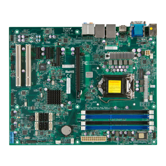
Chapter 1: Introduction Chapter 1 Introduction Overview Checklist Congratulations on purchasing your computer motherboard from an acknowledged leader in the industry. Supermicro boards are designed with the utmost attention to detail to provide you with the highest standards in quality and performance. Please check that the following items have all been included with your motherboard. - Page 14 C7Q67-H User’s Manual C7Q67-H Motherboard Image Note: All graphics shown in this manual were based upon the latest PCB Revision available at the time of publishing of the manual. The motherboard you've received may or may not look exactly the same as the graphics shown in this manual.
- Page 15 Chapter 1: Introduction C7Q67-H Motherboard Layout PCB EDGE C7Q67-H REV:1.00 HDMI DESIGNED IN USA JAUDIO1 HD AUDIO VGA/ JUSBLAN1 COM1 JUSBLAN2 LAN2 JPAC1 JPAC1:AUDIO 11/12 JHD_AC1 1-2:ENABLE 2-3:DISABLE Audio Front Panel JHD_AC1: ON:AC'97 OFF:HD Audio USB10/13 SLOT4 PCI-E 2.0 X1...
- Page 16 C7Q67-H User’s Manual C7Q67-H Quick Reference LAN 1 KB/MOUSE HDMI HD AUDIO COM1 USB 8/9 USB 10/13 LAN 2 USB 11/12 JPAC1 PCB EDGE SLOT3 C7Q67-H SLOT1 REV:1.00 HDMI DESIGNED IN USA SLOT7 AUDIO FP SLOT2 SLOT5 JAUDIO1 HD AUDIO...
- Page 17 Front Panel Accessible USB 2.0 Headers 0/1, 2/3, 4/5 USB 3.0 FP Front Panel Accessible USB 3.0 Header 0/1 HDMI Backpanel HDMI Port Backpanel VGA Port C7Q67-H LED Indicators Description Color/State Status LED1 Onboard Standby PWR LED Green: Solid on...
-
Page 18: Motherboard Features
C7Q67-H User’s Manual Motherboard Features Single 2nd Generation Intel® Core™ i7/i5/i3 DT processor in an LGA1155 socket. Memory Four (4) SDRAM slots support up to 32 GB of DDR3 Unbuf- fered, Non-ECC 1333/1066 memory Supports dual-channel memory bus DIMM sizes... - Page 19 Chapter 1: Introduction Audio Five (5) Female Mini Jacks for High Definition Audio on the Back Panel Front Panel Audio Header One (1) SP/DIF Optical Out on the back panel SP/DIF In and SP/DIF Out Headers Super I/O Nuvoton NCT6776F BIOS 64 Mb AMI BIOS SPI Flash BIOS...
-
Page 20: Block Diagram
C7Q67-H User’s Manual C7Q67-H Block Diagram C7Q67-H BLOCK DIAGRAM RoHS 6/6 DDR3 (CHA) PCIe2.0_x16 DIMM1A (Blue) PCIe x16 SLOT #7 INTEL LGA1155 DIMM1B 5.0GT/s 1333/1066MHz Sandy Bridge-DT DDR3 (CHB) (Socket-H2) DIMM2A (Blue) DIMM2B 1333/1066MHz VRD12 SVID VRM 12 x4 DMI... -
Page 21: Chipset Overview
Chapter 1: Introduction Chipset Overview The C7Q67-H supports a single 2nd generation Intel® Core i7/i5/i3 DT processor in the LGA 1155 Socket. Built upon the functionality and the capability of the Q67 Ex- press chipset, the motherboard provides substantial enhancement to system per- formance and storage capability for high performance platforms in a sleek package. -
Page 22: Special Features
Note: To avoid possible system overheating, please be sure to provide adequate airflow to your system. System Resource Alert This feature is available when the system is used with Supero Doctor III in the Windows OS environment or used with Supero Doctor II in Linux. Supero 1-10... -
Page 23: Acpi Features
Chapter 1: Introduction Doctor is used to notify the user of certain system events. For example, you can also configure Supero Doctor to provide you with warnings when the system temperature, CPU temperatures, voltages and fan speeds go beyond predefined thresholds. -
Page 24: Super I/O
C7Q67-H User’s Manual 2. To provide adequate power to SATA devices, please connect the SATA DOM PWR connector (JWF1) to the power supply. It is strongly recommended that you use a high quality power supply that meets ATX power supply Specification 2.02 or above. It must also be SSI compliant. (For more information, please refer to the web site at http://www.ssiforum.org/). -
Page 25: Installation
Chapter 2: Installation Chapter 2 Installation Static-Sensitive Devices Electrostatic-Discharge (ESD) can damage electronic com ponents. To avoid dam- aging your system board, it is important to handle it very carefully. The following measures are generally sufficient to protect your equipment from ESD. Precautions •... -
Page 26: Processor And Heatsink Installation
C7Q67-H User’s Manual Processor and Heatsink Installation Warning: When handling the processor package, avoid placing direct pressure on the label area of the fan. Important: Always connect the power cord last, and always remove it before adding, removing or changing any hardware components. Make sure that you in- stall the processor into the CPU socket before you install the CPU heatsink. - Page 27 Chapter 2: Installation 2. Gently lift the load lever to open the load plate. Remove the plastic cap. 3. Use your thumb and your index finger to hold the CPU at the North center edge and the South center edge of the CPU. North Center Edge South Center Edge 4.
- Page 28 C7Q67-H User’s Manual 5. Do not rub the CPU against the surface or against any pins of the socket to avoid damaging the CPU or the socket.) 6. With the CPU inside the socket, inspect the four corners of the CPU to make sure that the CPU is properly installed.
-
Page 29: Installing An Active Cpu Heatsink With Fan
Chapter 2: Installation Installing an Active CPU Heatsink with Fan 1. Locate the CPU Fan power connec- tor on the motherboard. (Refer to the layout on the right for the CPU Fan location.) 2. Position the heatsink so that the heatsink fan wires are closest to the CPU fan power connector and are Thermal Grease... - Page 30 C7Q67-H User’s Manual 7. Align the four heatsink fasten- ers with the mounting holes on the motherboard. Gently push the pairs of diagonal fasteners (#1 & #2, and #3 & #4) into the mounting holes until you hear a click. Also,...
-
Page 31: Removing The Heatsink
Chapter 2: Installation Removing the Heatsink Warning: We do not recommend that the CPU or the heatsink be removed. However, if you do need to remove the heatsink, please follow the instructions be- low to remove the heatsink and to prevent damage done to the CPU or other components. -
Page 32: Installing Ddr3 Memory
C7Q67-H User’s Manual Installing DDR3 Memory Note: Check the Supermicro website for recommended memory mod- ules. CAUTION Exercise extreme care when installing or removing DIMM modules to prevent any possible damage. PCB EDGE DIMM Installation C7Q67-H REV:1.00 HDMI DESIGNED IN USA... -
Page 33: Memory Support
Chapter 2: Installation Memory Support The C7Q67-H supports up to 32GB of Unbuffered (UDIMM) DDR3 Non-ECC 1333/1066 MHz in 4 memory slots. Populating these DIMM modules with a pair of memory modules of the same type and same size will result in interleaved memory, which will improve memory performance. - Page 34 C7Q67-H User’s Manual Possible System Memory Allocation & Availability System Device Size Physical Memory Remaining (-Available) (4 GB Total System Memory) Firmware Hub flash memory (System BIOS) 1 MB 3.99 Local APIC 4 KB 3.99 Area Reserved for the chipset 2 MB 3.99...
-
Page 35: Motherboard Installation
Then use a screwdriver to secure the motherboard onto the motherboard tray. Tools Needed Philips Screwdriver Standoffs Philips Screws Only if Needed Location of Mounting Holes PCB EDGE C7Q67-H REV:1.00 HDMI DESIGNED IN USA JAUDIO1 HD AUDIO VGA/ JUSBLAN1 COM1... -
Page 36: Installing The Motherboard
C7Q67-H User’s Manual Installing the Motherboard 1. Install the I/O shield into the back of the chassis. 2. Locate the mounting holes on the motherboard. (See the previous page.) 3. Locate the matching mounting holes on the chassis. Align the mounting holes on the motherboard against the mounting holes on the chassis. -
Page 37: Connectors/Io Ports
Connectors/IO Ports The I/O ports are color coded in conformance with the PC 99 specification. See the figure below for the colors and locations of the various I/O ports. Backplane I/O Panel PCB EDGE C7Q67-H REV:1.00 DESIGNED IN USA HDMI JAUDIO1... -
Page 38: Atx Ps/2 Keyboard/Mouse Ports
C7Q67-H User’s Manual ATX PS/2 Keyboard/Mouse PS/2 Keyboard/Mouse Pin Ports Definitions PS2 Keyboard PS2 Mouse The ATX PS/2 keyboard and Pin# Definition Pin# Definition PS/2 mouse are located next to KB Data Mouse Data the Back Panel USB Ports 8/9 on... -
Page 39: Universal Serial Bus (Usb)
H. Front Panel USB 2.0 #2/3 GND_DRAIN Ground for Signal Return I. Front Panel USB 2.0 #0/1 StdA_SSTX- SuperSpeed Transmitter J. Front Panel USB 3.0 #0/1 StdA_SSTX+ Differential Pair PCB EDGE C7Q67-H REV:1.00 HDMI DESIGNED IN USA JAUDIO1 HD AUDIO VGA/ JUSBLAN1 COM1 JUSBLAN2... -
Page 40: Ethernet Ports
C7Q67-H User’s Manual Ethernet Ports LAN Ports Pin Definition Two Gigabit Ethernet ports (LAN1/ Pin# Definition LAN2) are located next to the HD Au- P2V5SB SGND dio Connector on the I/O Backpanel to TD0+ Act LED provide network connections. These... -
Page 41: Front Accessible Audio Header
See Line_2_Right the tables at right for pin definitions Ground for these headers. Jack_Detect Line_2_Left A. Audio Header Ground PCB EDGE C7Q67-H REV:1.00 HDMI DESIGNED IN USA JAUDIO1 HD AUDIO VGA/ JUSBLAN1 COM1 JUSBLAN2... -
Page 42: Hdmi Port
C7Q67-H User’s Manual HDMI Port One HDMI (High-Definition Multimedia Inter- face) Port is located next to the VGA port on the I/O backpanel. This connector is used to display both high definition video and digital sound through an HDMI-capable display, using a single HDMI cable (not included). -
Page 43: Front Control Panel
Supermicro chassis. See the figure below for the descriptions of the front control panel buttons and LED indicators. Refer to the following section for descriptions and pin definitions. PCB EDGE C7Q67-H REV:1.00 HDMI DESIGNED IN USA... -
Page 44: Front Control Panel Pin Definitions
C7Q67-H User’s Manual Front Control Panel Pin Definitions Power LED Power LED Pin Definitions (JF1) The Power LED connection is located Pin# Definition on pins 15 and 16 of JF1. Refer to the table on the right for pin definitions. -
Page 45: Nic1/Nic2 (Lan1/Lan2)
Chapter 2: Installation NIC1/NIC2 (LAN1/LAN2) LAN1/LAN2 LED Pin Definitions (JF1) The NIC (Network Interface Controller) Pin# Definition LED connection for LAN port 1 is located 9/11 on pins 11 and 12 of JF1, and the LED 10/12 Ground connection for LAN Port 2 is on Pins 9 and 10. -
Page 46: Reset Button
C7Q67-H User’s Manual Reset Button The Reset Button connection is located Reset Button Pin Definitions (JF1) on pins 3 and 4 of JF1. Attach it to a Pin# Definition hardware reset switch on the computer Reset case to reset the system. Refer to the Ground table on the right for pin definitions. -
Page 47: Connecting Cables
Pin Definitions 4-Pin Processor PWR 24-Pin Main PWR Pins Definition 1 through 4 Ground 5 through 8 +12V (Required) PCB EDGE C7Q67-H REV:1.00 HDMI DESIGNED IN USA JAUDIO1 A. 24-Pin ATX Main PWR HD AUDIO VGA/ JUSBLAN1 COM1 JUSBLAN2... -
Page 48: Fan Headers (Fan 1 ~ Fan 4)
C7Q67-H User’s Manual Fan Headers (Fan 1 ~ Fan 4) Fan Header Pin Definitions The C7Q67-H has four fan headers (Fan 1~Fan Pin# Definition 4). These fans are 4-pin fan headers. Although Ground (Black) pins 1-3 of the fan headers are backward com- 2.5A/+12V... -
Page 49: Internal Buzzer (Sp1)
If you wish to use an external speaker, Pins1~4 External Speaker close Pins 1~4 with a cable. See the table on the right for pin definitions. A. Internal Buzzer B. Speaker Header PCB EDGE C7Q67-H REV:1.00 DESIGNED IN USA HDMI JAUDIO1 HD AUDIO VGA/ JUSBLAN1... -
Page 50: Onboard Power Led (Jled)
C7Q67-H User’s Manual Onboard Power LED (JLED) Onboard PWR LED Pin Definitions An onboard Power LED header is lo- Pin# Definition cated at JLED. This Power LED header is connected to Front Control Panel No Connection located at JF1 to indicate the status of Connection to PWR system power. -
Page 51: Dom Pwr Connector (Jsd1)
Ground (You must also have a LAN card with Wake-up a Wake-On-LAN connector and cable to use this feature.) A.DOM PWR B. JWOL PCB EDGE C7Q67-H REV:1.00 HDMI DESIGNED IN USA JAUDIO1 HD AUDIO VGA/ JUSBLAN1 COM1... -
Page 52: Wake-On-Ring (Jwor)
C7Q67-H User’s Manual Wake-On-Ring (JWOR) Wake-On-Ring Pin Definitions The Wake-On-Ring header is located Pin# Definition at JWOR. This function allows your Ground computer to wake up when receiving Wake-up an incoming call to the modem while in the suspend state. This header is provided to support legacy devices. -
Page 53: Jumper Settings
Enabled (default) Port 2 on the motherboard. See the table Disabled on the right for jumper settings. The de- fault setting is enabled. A. LAN Port 2 Enable PCB EDGE C7Q67-H REV:1.00 DESIGNED IN USA HDMI JAUDIO1 HD AUDIO VGA/... -
Page 54: Cmos Clear (Jbt1)
C7Q67-H User’s Manual CMOS Clear (JBT1) JBT1 is used to clear the saved system setup stored in the CMOS chip. To clear the contents of the CMOS, completely shut down the system, remove the AC power cord and then short JBT1 with a jumper. Remove the jumper before powering on the system again. -
Page 55: Me Recovery Enable (Jpme1)
AC' 97 Front Panel Audio support. See HD Audio Front Panel (Default) the table on the right for jumper settings. A. ME Recovery B. HD Audio/AC'97 Audio Select PCB EDGE C7Q67-H REV:1.00 HDMI DESIGNED IN USA JAUDIO1 HD AUDIO VGA/ JUSBLAN1... -
Page 56: Audio Enable (Jpac1)
C7Q67-H User’s Manual Audio Enable (JPAC1) Audio Enable/Disable Jumper Settings JPAC1 allows you to enable or disable Both Jumpers Definition the onboard audio support. The default Pins 1-2 Enabled position is on pins 1 and 2 to enable on- Pins 2-3 Disabled board audio connections. -
Page 57: Onboard Indicators
Cable Connected installing any component. See the layout below for the LED location. A. LAN Port 1 B. LAN Port 2 C. PWR LED PCB EDGE C7Q67-H REV:1.00 DESIGNED IN USA HDMI JAUDIO1 HD AUDIO VGA/ JUSBLAN1... -
Page 58: Sata Connections
The SATA 3.0 ports support RAID 0, 1 while the SATA 2.0 ports support RAID 0, 1, 5 &10. These Serial Link connections provide faster data transmission than legacy Parallel ATA. See the table on the right for pin definitions. SATA 2.0/3.0 Connectors Pin Definitions C7Q67-H SATA Connector Types Pin# Signal Port# Connection Type... -
Page 59: Troubleshooting
Chapter 3: Troubleshooting Chapter 3 Troubleshooting Troubleshooting Procedures Use the following procedures to troubleshoot your system. If you have followed all of the procedures below and still need assistance, refer to the ‘Technical Support Procedures’ and/or ‘Returning Merchandise for Service’ section(s) in this chapter. Always disconnect the AC power cord before adding, changing or installing any hardware components. -
Page 60: No Video
C7Q67-H User’s Manual No Video 1. If the power is on, but you have no video--in this case, you will need to re- move all the add-on cards and cables first. 2. Use the speaker to determine if any beep codes exist. (Refer to Appendix A for details on beep codes.) -
Page 61: Frequently Asked Questions
Frequently Asked Questions Question: What type of memory does my motherboard support? Answer: The C7Q67-H supports up to 32GB of unbuffered Non-ECC DDR3 SDRAM (1.5V, 1333/1066 MHz). See Section 2-3 for details on installing memory. Question: How do I update my BIOS? Answer: We do NOT recommend that you upgrade your BIOS if you are not experiencing any problems with your system. - Page 62 Note: Always use the file named “ami.bat” to update the BIOS, and insert a space between "ami.bat" and the filename. The BIOS-ROM-filename will bear the motherboard name (i.e., C7Q67-H) and build version as the extension. For example, "C7Q67-H0.115".When completed, your system will automatically reboot.
-
Page 63: Battery Removal And Installation
USB floppy drive instead of the onboard floppy drive. For the IPMI jumper location, please check Chapter 1. Question: What is the heatsink part number for my C7Q67-H motherboard? Answer: For the 1U passive heatsink, ask for SNK-P0046P (back plate is included). -
Page 64: Returning Merchandise For Service
C7Q67-H User’s Manual Battery Installation 1. To install an onboard battery, follow the steps 1& 2 above and continue below: 2. Identify the battery's polarity. The positive (+) side should be facing up. 3. Insert the battery into the battery holder and push it down until you hear a click to ensure that the battery is securely locked. -
Page 65: Introduction
BIOS Introduction This chapter describes the AMI BIOS Setup Utility for the C7Q67-H. The ROM BIOS is stored in a Flash EEPROM and can be easily updated. This chapter describes the basic navigation of the AMI BIOS Setup Utility setup screens. -
Page 66: How To Start The Setup Utility
C7Q67-H User’s Manual How to Start the Setup Utility Normally, the only visible Power-On Self-Test (POST) routine is the memory test. As the memory is being tested, press the <Delete> key to enter the main menu of the AMI BIOS Setup Utility. From the main menu, you can access the other setup screens. -
Page 67: System Time/System Date
Day MM/DD/YY format. The time is entered in HH:MM:SS format. Note: The time is in the 24-hour format. For example, 5:30 P.M. appears as 17:30:00. The following BIOS items will also be displayed: Supermicro C7Q67-H BIOS Version ME Firmware Version Build Date... -
Page 68: Advanced Setup Configurations
C7Q67-H User’s Manual Advanced Setup Configurations Use the arrow keys to select Boot Setup and press <Enter> to access the submenu items: Aptio Setup Utility - Copyright (C) 2011 American Megatrends, Inc. Main Advanced Security Boot Exit System Boot Feature Setting. -
Page 69: Power Configuration
Chapter 4: AMI BIOS as bootable disks. If this item is set to Disabled, the ROM BIOS of the host adap- tors will not capture Interrupt 19, and the drives attached to these adaptors will not function as bootable devices. The options are Enabled and Disabled. Power Configuration ... -
Page 70: Adjacent Cache Line Prefetch
C7Q67-H User’s Manual Adjacent Cache Line Prefetch (Available when supported by the CPU) Select Enabled for the CPU to prefetch both cache lines for 128 bytes as comprised. Select Disabled for the CPU to prefetch both cache lines for 64 bytes. The options are Disabled and Enabled. -
Page 71: Factory Long Duration Power Limit
Chapter 4: AMI BIOS consumption and heat dissipation. Please refer to Intel’s web site for detailed information. The options are Disabled and Enabled. P-STATE Coordination This feature selects the type of coordination for the P-State of the processor. P-State is a processor operational state that reduces the processor's voltage and frequency. -
Page 72: Recommended Short Duration Power Limit
C7Q67-H User’s Manual Recommended Short Duration Power Limit The system's power consumption may exceed the processor's default power setting and the Short Duration Power Limit when operating in the turbo mode. This feature displays the Short Duration Power Limit value recommended by the manufacturer for turbo mode operation. -
Page 73: Pci Express Port
Chapter 4: AMI BIOS PCI Express Port This feature can force to enable or disable the onboard PCI Express port. The options are Disabled, Enabled and Auto. PEG Force Gen1 This feature forces Gen1 support on the PCI Express Graphics (PEG) port. -
Page 74: Wake On Lan From S5
C7Q67-H User’s Manual Wake on LAN from S5 Select Enabled to enable the capabiltiy to 'wake-up' the system from the S5 power state (Soft Off State) through the Ethernet controller. The set- tings are Enabled and Disabled. USB Functions This feature will enable or disable the motherboard's USB functions. -
Page 75: Pch Io Port 80 Decoding
Chapter 4: AMI BIOS PCH IO Port 80 Decoding Selects Port 80 Decoding between LPC or PCI for debug purposes. The settings are PCI and LPC. Deep Sx Select Enabled to enable Deep Sleep State support. The settings are Enabled and Disabled. On Board Chip Configuration ... -
Page 76: Port 0 ~ Port 5
C7Q67-H User’s Manual PLX PEX8604-BA PCIe Gen2 Switch Port 0 ~ Port 5 This feature activates the specified PEX8604 PCIe port. The options are Enabled and Disabled. Read Pacing This feature activates Read Pacing on PEX8604 chip. The options are Enabled and Disabled. -
Page 77: Pcie/Pci/Pnp Configuration
Chapter 4: AMI BIOS IDE Mode The following items are displayed when IDE Mode is selected: Serial-ATA Controller 0~1 This feature is used to activate/deactivate the SATA controller, and sets the compatibility mode. The options are Enhanced and Compatible. The default of Serial-ATA Controller 1 is Enhanced. -
Page 78: Pcie Max Read Request Size
C7Q67-H User’s Manual PCIe Max Read Request Size This item manually sets the maximum read request size of the PCI Express device or allows the system BIOS to choose the value (Auto). The options are Auto, 128 Bytes, 256 Bytes, 512 Bytes, 1024 Bytes, 2048 Bytes and 4096 Bytes PCI Slot 1 &... -
Page 79: Ite Lpc I/O - It8760
Chapter 4: AMI BIOS S1 (OS Control) - Enables system wake up from S1 (default). S5 (OS Control) - Enables system wake up from S1/S3/S4/S5. Force Enable - Wake up support is always enabled regardless whether it is disabled in the O/S. Force Disable - Wake up support is always disabled regardless whether it is enabled in the O/S. -
Page 80: Cpu Temperature
C7Q67-H User’s Manual CPU Temperature This feature displays the CPU temperature status in text ("Low", "Medium" or "High"): Low – This level is considered as the ‘normal’ operating state. The CPU temperature is well below the CPU ‘Temperature Tolerance’. The mother- board fans and CPU will run normally as configured in the BIOS (Fan Speed Control). -
Page 81: Suspend Mode
Chapter 4: AMI BIOS synchronizing multimedia streams, providing smooth playback and reducing the de- pendency on other timestamp calculation devices, such as an x86 RDTSC Instruc- tion embedded in the CPU. The High Performance Event Timer is used to replace the 8254 Programmable Interval Timer. -
Page 82: Security Settings
C7Q67-H User’s Manual Security Settings Aptio Setup Utility - Copyright (C) 2011 American Megatrends, Inc. Main Advanced Security Boot Exit Set Setup Administrator Password Description Password. If ONLY the administrator’s password is set, then this only limits access to Setup and is only asked for when entering Setup. -
Page 83: Boot Settings
Chapter 4: AMI BIOS Boot Settings Aptio Setup Utility - Copyright (C) 2011 American Megatrends, Inc. Main Advanced Security Boot Exit Setup Prompt Timeout Number of seconds to wait for setup activation key. 65535 (0xFFFF) means indefinite Boot Options Priority waiting. -
Page 84: Exit Options
C7Q67-H User’s Manual Exit Options Aptio Setup Utility - Copyright (C) 2011 American Megatrends, Inc. Main Advanced Security Boot Exit Exit system setup after saving Save Changes and Exit the changes. Discard Changes and Exit Discard Changes Restore Defaults Save as User Defaults... -
Page 85: Restore Defaults
Chapter 4: AMI BIOS Restore Defaults To set this feature, select Restore Defaults from the Exit menu and press <Enter>. These are factory settings designed for maximum system stability, but not for maximum performance. Save As User Defaults To set this feature, select Save as User Defaults from the Exit menu and press <En- ter>. - Page 86 C7Q67-H User’s Manual Notes 4-22...
-
Page 87: A-1 Bios Error Beep Codes
Appendix A: POST Error Beep Codes Appendix A BIOS Error Beep Codes During the POST (Power-On Self-Test) routines, which are performed each time the system is powered on, errors may occur. Non-fatal errors are those which, in most cases, allow the system to continue with bootup. - Page 88 C7Q67-H User’s Manual Notes...
-
Page 89: Software Installation Instructions
Appendix B: Software Installation Instructions Appendix B Software Installation Instructions B-1 Installing Drivers After you've installed the Windows Operating System, a screen as shown below will appear. You are ready to install software programs and drivers that have not yet been installed. To install these software programs and drivers, click the icons to the right of these items. -
Page 90: Configuring Superdoctor ® Iii
C7Q67-H User’s Manual B-2 Configuring SuperDoctor ® The SuperDoctor III program is a Web-based management tool that supports remote management capability. It includes Remote and Local Management tools. The local management tool is called the SD III Client. The SuperDoctor III program included on the CDROM that came with your motherboard allows you to monitor the envi- ronment and operations of your system. - Page 91 Appendix B: Software Installation Instructions SuperDoctor III Interface Display Screen-II (Remote Control) Note: The SuperDoctor III software and manual may be downloaded from our Website at: http://www.supermicro.com/products/accessories/software/SuperDoctorIII.cfm. For Linux, we still recommend that you use SuperDoctor II, this version is also available for download at the link above.
- Page 92 C7Q67-H User’s Manual Notes...
-
Page 93: Uefi Bios Recovery Instructions
Appendix C: UEFI BIOS Recovery Appendix C UEFI BIOS Recovery Instructions Warning! Do not upgrade the BIOS unless your system has a BIOS-related issue. Flashing the wrong BIOS can cause irreparable damage to the system. In no event shall Supermicro be liable for direct, indirect, special, incidental, or consequential damages arising from a BIOS update. - Page 94 C7Q67-H User’s Manual a USB CD/DVD ROM/RW device can be used for this purpose. However, a USB Hard Disk drive cannot be used for BIOS recovery at this time. To perform UEFI BIOS recovery using a USB-attached device, follow the instruc- tions below.
- Page 95 Appendix C: UEFI BIOS Recovery 5. When the screen as shown above displays, using the arrow key, select the item- "Proceed with flash update" and press the <Enter> key. You will see the progress of BIOS Recovery as shown in the screen below. Note: Do not interrupt the process of BIOS flashing until it is com- pleted.
- Page 96 C7Q67-H User’s Manual 8. When a DOS prompt appears, enter AMI.BAT BIOSname.### at the prompt. Note: Do not interrupt this process until BIOS flashing is completed. 9. After seeing the message that BIOS update is completed, unplug the AC pow- er cable from the power supply to clear CMOS, and then plug the AC power cable in the power supply again to power on the system.
- Page 97 (Disclaimer Continued) The products sold by Supermicro are not intended for and will not be used in life support systems, medical equipment, nuclear facilities or systems, aircraft, aircraft devices, aircraft/emergency communication devices or other critical systems whose failure to perform be reasonably expected to result in significant injury or loss of life or catastrophic property damage.
Need help?
Do you have a question about the C7Q67-H and is the answer not in the manual?
Questions and answers