Table of Contents
Advertisement
Instructions-Parts
Automatic AirPro
Spray Guns
Conventional, HVLP, and Compliant guns for spraying paints and coatings.
See page 2 for model information.
100 psi (0.7 MPa, 7 bar) Maximum Working Fluid Pressure
100 psi (0.7 MPa, 7 bar) Maximum Working Air Pressure
Important Safety Instructions
Read all warnings and instructions in this
manual. Save these instructions.
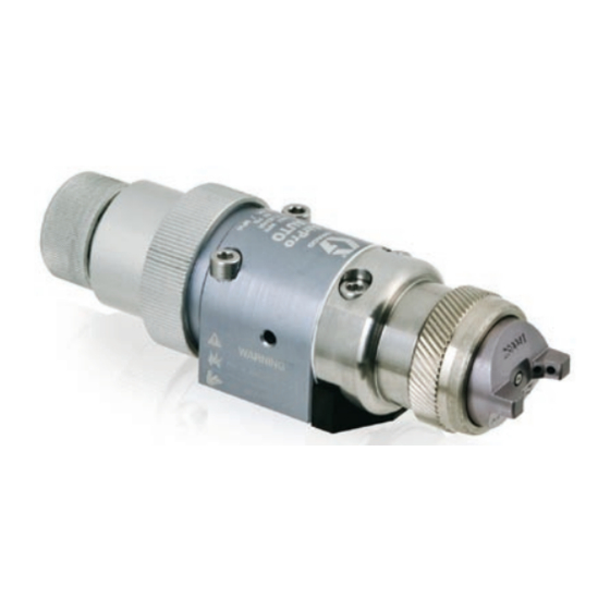
Part 24A749 Conventional Gun shown
mounted on Part 288217 Manifold
Part 24A753 Conventional Gun with fluid control
ti13585a
shown mounted on Part 288223 Manifold.
®
313516C
ti13586a
II 2 G c IIB T6
Advertisement
Table of Contents
Troubleshooting

Related Manuals for Graco AirPro 313516C


Summary of Contents for Graco AirPro 313516C
- Page 1 Instructions-Parts Automatic AirPro Spray Guns Conventional, HVLP, and Compliant guns for spraying paints and coatings. See page 2 for model information. 100 psi (0.7 MPa, 7 bar) Maximum Working Fluid Pressure 100 psi (0.7 MPa, 7 bar) Maximum Working Air Pressure Important Safety Instructions Read all warnings and instructions in this manual.
-
Page 2: Table Of Contents
Models Contents Models ......2 Warnings ......3 Selection Charts . -
Page 3: Warnings
Warnings The following warnings are for the setup, use, grounding, maintenance, and repair of this equip- ment. The exclamation point symbol alerts you to a general warning and the hazard symbol refers to procedure-specific risk. Refer back to these warnings. Additional, product-specific warnings may be found throughout the body of this manual where applicable. - Page 4 Warnings PRESSURIZED EQUIPMENT HAZARD Fluid from the gun/dispense valve, leaks, or ruptured components can splash in the eyes or on skin and cause serious injury. • Follow Pressure Relief Procedure in this manual, when you stop spraying and before cleaning, checking, or servicing equipment. •...
-
Page 5: Selection Charts
Selection Charts TERMS Light Fluid: Up to 18 seconds with No. 2 Zahn cup (20 centipoise) Medium Fluid:19 to 28 seconds with No. 2 Zahn cup (20-64 centipoise) General Metal Applications Needle/ Assembly Nozzle Kit Part No. Type Part No. 24B333 Conventional 24B332... -
Page 6: Compliant Guns
Selection Charts High Wear Applications Needle/ Assembly Nozzle Kit Part No. Type Part No. 24A774✠ Conventional 24A693 24A775✠ Conventional 24A694 24B336✠ Conventional 24B358 24C316✠ Conventional 24C142 24A776✠ HVLP 24A695 24A777✠ HVLP 24A696 24A778✠ Compliant 24A695 24A779✠ Compliant 24A696 ✠ Needle tip and nozzle exit constructed from tungsten carbide. Wood Applications Needle/ Assembly... -
Page 7: Conventional Guns
Conventional Guns An airspray gun has excellent atomization and high production rates typically with some reduction in transfer efficiency. Proper Needle/Nozzle Selection The spray gun's needle/nozzle kits range in size to provide different fluid flow rates. As a general guideline, use the fluid nozzle that will give the required flow with the needle fully trig- gered at a fluid pressure of 5–20 psi (0.035–0.14 MPa, 0.35–1.4 bar). -
Page 8: Air Flow
Air Flow Air Flow See the chart to determine air consumption. Add the air consumption values shown for the atom- izing air and fan air pressures to get the total air consumption. For example, air cap 24B544 with 20 psi atomizing air pressure uses 3 scfm atomizing air. A 30 psi fan inlet pressure adds 5 scfm fan air for a total of 8 scfm air consumption. - Page 9 Atomizing Air Manifold Inlet Pressure Air cap psi (MPa, bar) 10 (0.07, 0.7) 20 (0.14, 1.4) 30 (0.21, 2.1) 288863 40 (0.28, 2.8) 50 (0.34, 3.4) 27* (0.19, 1.9) 10 (0.07, 0.7) 20 (0.14, 1.4) 289784 30 (0.21, 2.1) 40 (0.28, 2.8) 50 (0.34, 3.4) 10 (0.07, 0.7) 20 (0.14, 1.4)
-
Page 10: Installation
Installation Installation The Automatic AirPro spray gun can spray most coatings or finishes currently being used for automotive, industrial, aerospace, marine, wood, plastic and architectural applications, while easily operating from paint delivery sys- tems, such as pressure pots or remote pumps for production line operation. -
Page 11: Install Air Fittings
Install Air Fittings 1. Install the supplied 1/4 in. tube fitting into the cylinder (CYL) air port. 2. Install 3/8 in. tube fittings into the atomiza- tion (ATOM) air port and the fan (FAN) air port. . 2: Air Fittings Ground System The following grounding instructions are mini- mum requirements for a system. -
Page 12: Mount Gun
Installation Mount Gun Reciprocating Arm Rod Mount To mount the gun on a reciprocating arm rod [0.5 in. (13 mm) diameter maximum]: 1. Insert the mounting bar (A) through the hole in the manifold as shown in F NOTE: Use the 1/8 in. alignment pin (P) to assist in orienting the gun. - Page 13 Retrofit Adapter Plate The retrofit adapter plate enables the manifold to be attached to a variety of bolt patterns. To mount the gun using the retrofit adapter plate (Kit 288197; See Accessories, page 34): 1. Mount adapter plate to manifold using the three screws provided with the kit.
-
Page 14: Setup
Setup Setup Connect Air Line NOTE: • You must install an air pressure regula- tor (F) on each gun air line to control air pressure to the gun. See F • If your regulated air source does not have a filter, install an air filter (G) on each air line to ensure a dry, clean air supply to the gun. -
Page 15: Position Air Cap
N Cylinder Air Inlet: accepts 1/4 in. (6.3 mm) O.D. tubing P Atomization Air Inlet: 3/8 in, (9.5 mm) O.D. tubing R Fan Air Inlet: 3/8 in. (9.5 mm) O.D. tubing S Fluid Inlet: 1/4 npsm T Fluid Outlet (circulating gun only): 1/4 npsm Side Mounted Manifold Ports T (or S) ATOM... -
Page 16: Adjust Spray Pattern
Setup Adjust Spray Pattern Do not exceed 100 psi (0.7 MPa, 7 bar) maximum fluid and air pressure. Higher pressures can cause parts to rupture and result in serious injury. Use the fluid pressure regulator to adjust the spray gun fluid flow. Some models are equipped with a fluid control knob to make pre- cise fluid flow adjustments. - Page 17 NOTE: HVLP and Compliant Gun Limits HVLP Guns: local laws may limit the maximum pressure to 10 psi (70 kPa, 0.7 bar) at the air cap for compliance. See the table on page 7 for maximum HVLP/Compliant manifold inlet pressures. To measure pressure at the air cap, use the appropriate HVLP Pressure Verifica- tion Kit.
-
Page 18: Operation
Operation Operation Pressure Relief Procedure 1. Turn off all bleed type air valves and all other air and fluid supplies to the gun. 2. Trigger the gun into a grounded metal waste container to relieve air and fluid pres- sure. . -
Page 19: Daily Gun Care
Daily Gun Care NOTICE Methylene chloride with formic or propi- onic acid is not recommended as a flush- ing or cleaning solvent with this gun as it will damage aluminum and nylon compo- nents. Solvent left in gun air passages could result in a poor quality paint finish. Do not use any cleaning method which may allow solvent into the gun air passages. -
Page 20: General System Maintenance
Operation General System Maintenance • Perform Pressure Relief Procedure, page 18. • Clean the fluid and air line filters daily. • Check for any fluid leakage from the gun and fluid hoses. Tighten fittings or replace equipment as needed. • Flush the gun before changing colors and whenever you are done operating the gun. -
Page 21: Troubleshooting
Troubleshooting NOTE: Check all possible remedies in the trou- bleshooting charts before disassembling the gun. General Troubleshooting Problem Fluid leakage through venting holes. Air leakage through venting hole. Worn o-ring (9) or gasket (15). Air leakage from back of gun. Air does not trigger. -
Page 22: Spray Pattern Troubleshooting
Troubleshooting Problem Fluid needle will not trigger. Fluid does not shut off. Spray Pattern Troubleshooting Problem Fluid flow is fluttering while spray- ing. Fluid flow fades while spraying high viscosity fluids. Pattern becomes off-set or heavy on ends. Gun fluid pressure is too high with gun triggered. -
Page 23: Service
Service NOTE: Air Section Repair Kit 288171 and Fluid Section Repair Kit 24B675 are available for purchase separately. Numbers in parenthe- sis in the text refer to the reference numbers in the figures and in the parts list. Disassembly 1. Perform Pressure Relief Procedure, page 18. - Page 24 Service 13. Remove all o-rings from the piston (3) and stems (T). Check that the stems are solidly in place. If they are loose, replace the entire piston assembly (3). 14. Perform the following applicable step: a. Non-circulating guns: Remove the fluid outlet port plug (19), and gasket (22) from the fluid housing (2).
- Page 25 Reassembly 1. Non-circulating guns only: Lubricate the backup ring (20†) and o-ring (21†) and install them on the fluid outlet port plug (19). Install the plug in the fluid outlet port of the fluid housing (2). See F 2. All guns: Reinstall the gasket (22) in the fluid housing (2).
-
Page 26: Parts
Parts .Parts Parts SERVICE NOTES: Torque to 35-45 in-lb (4.0-5.1 N•m). Lubricate threads with anti-seize lubricant. Lubricate with light-weight oil. Tighten cap (4) until it bottoms out. Apply semi-permanent anaerobic sealant. Torque to 4-5 in-lb (0.45-0.57 N•m). Torque to 95-105 in-lb (10.7-11.8 N•m). Apply semi-permanent anaerobic sealant to two threads at end of needle shaft. - Page 27 Ref. Part Description ----- HOUSING, piston 24B676 HOUSING, fluid 240895 PISTON, assembly See pages 28-29 CAP, piston See pages 28-29 NEEDLE, assembly See pages 28-29 TIP, needle 114139 SPRING, compres- sion 114138 SPRING, compres- sion 115066 O-RING, fluoroelasto- 111450 O-RING, fluoroelasto- 10* 111504 O-RING, fluoroelasto- 11* 112319...
-
Page 28: Repair Kits
Repair Kits Repair Kits NOTE: Alternate nozzle sizes are also available. See Accessories, page 34. General Metal Applications Nozzle Orifice Size Gun Part Number Spray Type in. (mm) 24B333 Conventional 0.020 (0.5) 24A747 Conventional 0.030 (0.8) 24A748 Conventional 0.042 (1.1) 24A749 Conventional 0.055 (1.4) 24A750 Conventional 0.070 (1.8) 24B334... - Page 29 High Wear Applications Nozzle Orifice Size Gun Part Number Spray Type in. (mm) 24A774✠ Conventional 0.059 (1.5) 24A775✠ Conventional 0.070 (1.8) 24B336✠ Conventional 0.086 (2.2) 24C316✠ Conventional 0.110 (2.8) 24A776✠ 0.059 (1.5) HVLP 24A777✠ 0.070 (1.8) HVLP 24A778✠ 0.059 (1.5) Compliant 24A779✠...
- Page 30 Repair Kits Part No. 288221 Manifold with bottom fluid ports Ref. Part Description ----- MANIFOLD, bottom fluid ports 120388 FITTING, tube, air inlet; 1/4 in. OD tube x 1/8 npt(m) 114246 SCREW, set; 5/16, 0.437 in. long 166846 NIPPLE, SST; 1/4 npsm, straight pipe thread x 1/4 npt 120389 FITTING, tube, air line;...
- Page 31 Part No. 288223 North America Low Pressure Manifold with side fluid ports and fan adjustment valve Part No. 24C342 International Low Pressure Manifold with side fluid ports and fan adjustment valve Ref. Part No. Description ----- MANIFOLD, fan adjustable 243949 VALVE, fan, assy.
- Page 32 Repair Kits Part No. 288217 North America Manifold with side fluid ports Part No. 288218 International Manifold with side fluid ports Ref. Part No. Description ----- MANIFOLD, side fluid ports FITTING, tube, air inlet 120388❖ 1/4 in. OD tube x 1/8 npt(m) 120538◆...
- Page 33 Part No. 288160 Rear Port Manifold, North America Part No. 288211 Rear Port Manifold, International Ref. No. Part No. Description 101 ----- MANIFOLD, aluminum FITTING, fluid path 15H521❖ 1/4 npsm 15J003◆ #5 JIC 105 116475 SCREW, SHCS, M4 x 12 106 120353 O-RING, PTFE 107 15J077...
-
Page 34: Accessories
Accessories Accessories Alternate Nozzle Sizes Gun Type Application Conventional Conventional HVLP General Metal HVLP Compliant Compliant Conventional HVLP Wood Compliant Stainless Steel Air Cap Kits Gun Type Application Conventional Conventional General Metal HVLP Compliant Cleaning Brush 105749 For use in cleaning gun. Lubricant 111265 One 4 oz. - Page 35 HVLP Pressure Verification Kit For use in checking air cap atomizing and fan pattern air pressure at various supply air pres- sures. Not to be used for actual spraying. Install the kit air cap on the gun. Turn on the air to the gun, then trigger the gun and read the air pressure on the gauge.
-
Page 36: Dimensions
Dimensions Dimensions Manifold Models 288217 or 288218, All Gun Models 2.0 in. (50.8 mm) 3.9 in. (99.1 mm) ti13880a . 26 Manifold Model 288221, All Gun Models 2.0 in. (50.8 mm) 1.9 in. (48.3 mm) ti13882a . 27 5.3 in. (134.6 mm) 6.4 in. - Page 37 Manifold Model 288223 or 24C342, All Gun Models 2.0 in. (50.8 mm) 3.8 in. (96.5 mm) ti13884a . 28 Manifold Model 288160 or 288211, All Gun Models 2.0 in. (50.8 mm) 1.8 in. (45.7 mm) ti13886a . 29 313516C 5.3 in. (134.6 mm) 6.4 in.
-
Page 38: Mounting Hole Layouts
Mounting Hole Layouts Mounting Hole Layouts Manifold Models 288217 or 288218, All Gun Models 0.16 in. (4.1 mm) 0.5 in. (12.7 mm) mounting hole . 30 0.4 in. 0.92 in. (23.4 mm) (10.2 mm) 1.5 in. (38.1 mm) Two M5 x 0.8 x 0.25 in. (6.3 mm) holes 1.75 in. - Page 39 Manifold Model 288221, All Gun Models 0.18 in. (4.6 mm) 0.50 in. (12.7 mm) mounting hole . 31 313516C 0.92 in. 0.4 in. (10.2 mm) (23.4 mm) 2.1 in. (53.3 mm) Mounting Hole Layouts Two M5 x 0.8 x 0.25 in. (6.3 mm) holes 1.75 in.
- Page 40 Mounting Hole Layouts Manifold Model 288223 or 24C342, All Gun Models Four M6 x 1.0 x 0.34 in. 2.0 in. (6.3 mm) holes 0.216 in. (50.8 mm) (5.5 mm) 0.225 in. (5.7 mm) 1.75 in. 1.3 in. (44.4 mm) (33 mm) ti13889a 3.0 in.
- Page 41 Mounting Hole Layouts Manifold Model 288160 or 288211, All Gun Models Two M5 x 0.8 x 0.25 in. (6.3 mm) holes 0.92 in. 0.4 in. (23.4 mm) (10.2 mm) 0.19 in. (4.8mm) 1.75 in. 1.375 in. (44.4 mm (34.9 mm Two 0.13 diameter x 0.31 in.
- Page 42 Mounting Hole Layouts Retrofit Adapter Plate 288197 For use with manifold models 288217, 288218, 288221, 288216, and 288211 1.4 in. (34.9 mm) . 34 2.0 in. (51 mm) 0.74 in. (18.7 mm) ti8178a 2.3 in. (57.7 mm) ti13600a 313516C...
-
Page 43: Technical Data
Technical Data Maximum Working Fluid Pressure ....100 psi (0.7 MPa, 7 bar) Maximum Working Air Pressure..... 100 psi (0.7 MPa, 7 bar) Maximum HVLP and Compliant Gun Inbound Air Pressure . -
Page 44: Graco Standard Warranty
Graco Standard Warranty Graco warrants all equipment referenced in this document which is manufactured by Graco and bearing its name to be free from defects in material and workmanship on the date of sale to the original purchaser for use. With the exception of any special, extended, or limited warranty published by Graco, Graco will, for a period of twelve months from the date of sale, repair or replace any part of the equipment determined by Graco to be defective.
Need help?
Do you have a question about the AirPro 313516C and is the answer not in the manual?
Questions and answers