Table of Contents
Advertisement
Repair
Electric Airless Sprayers
- For Portable Airless Spraying of Architectural Coatings and Paints -
3300 psi (227 bar, 22.7 MPa) Maximum Working Pressure
IMPORTANT SAFETY INSTRUCTIONS
Read all warnings and instructions in this
manual. Save these instructions.
ti14838a
695/795 Premium Hi-Boy
ti15036a
MARK V
695/795
ti15035a
1095/1595 Premium Hi-Boy
ti15034a
Related Manuals:
Operation
Parts
Gun
3A0157A
ENG
3A0156
3A0158
311861
Advertisement
Table of Contents
Troubleshooting

Related Manuals for Graco 1095 Premium Hi-Boy


Summary of Contents for Graco 1095 Premium Hi-Boy
- Page 1 Repair Electric Airless Sprayers - For Portable Airless Spraying of Architectural Coatings and Paints - 3300 psi (227 bar, 22.7 MPa) Maximum Working Pressure IMPORTANT SAFETY INSTRUCTIONS Read all warnings and instructions in this manual. Save these instructions. ti14838a 695/795 Premium Hi-Boy ti15036a MARK V ti15034a...
- Page 2 Models: Models: 695 ULTRA MAX lIl Model QuikReel Hi-Boy ✓ ✓ 258719 ✓ 258720 258722 258872 ✓ 258873 258874 ✓ 258876 ✓ ✓ 258877 ✓ ✓ 826124 ✓ 826125 826127 795 ULTRA MAX III Model QuikReel Hi-Boy ✓ ✓ 258723 ✓...
-
Page 3: Table Of Contents
Table of Contents Models: ........2 Table of Contents . -
Page 4: Grounding Instructions
Warnings Warnings The following warnings are for the setup, use, grounding, maintenance and repair of this equipment. The exclamation point symbol alerts you to a general warning and the hazard symbol refers to procedure-specific risks. Refer back to these warnings. Additional, product-specific warnings may be found throughout the body of this manual where appli- cable. - Page 5 Use Graco conductive or grounded high-pressure airless paint sprayer hoses. • Do not clean with materials having flash points lower than 70° F (21° C). Use water-based material or mineral spirits-type material only.
- Page 6 Warnings EQUIPMENT MISUSE HAZARD Misuse can cause death or serious injury. • Always wear appropriate gloves, eye protection, and a respirator or mask when painting. • Do not operate or spray near children. Keep children away from equipment at all times. •...
-
Page 7: Component Identification
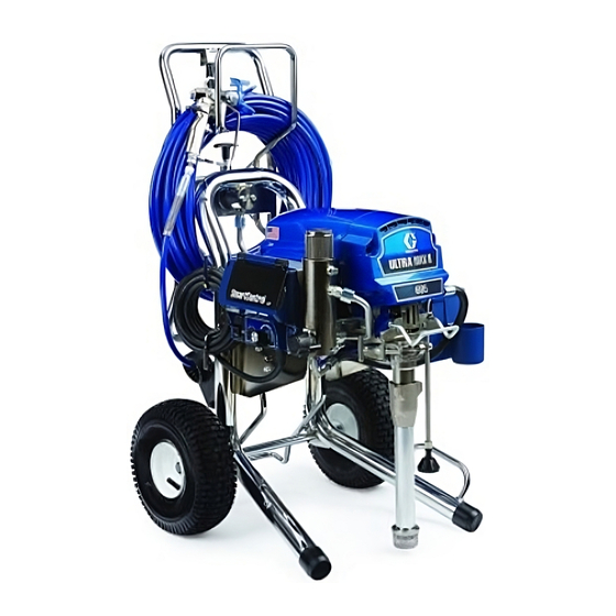
Component Identification Premium Digital Display ON/OFF switch ™ WatchDog Switch (not available on Mark V) Pressure Control Prime / Spray Valve Filter Siphon Tube Pump Bearing Housing / ProConnect 10 Drain Tube 11 Trigger Lock 12 Model/serial tag 13 Hose Reel 3A0157A ™... -
Page 8: Pressure Relief Procedure
Pressure Relief Procedure Pressure Relief Procedure 1. Turn power OFF. Wait 7 seconds for power to dissipate. ti4265a 2. Lock gun trigger safety. Remove guard and SwitchTip. ti10166a 3. Turn pressure to lowest setting. Trigger gun to relieve pressure. 4. Put drain tube in pail. Turn prime valve down to DRAIN position. -
Page 9: Grounding
Grounding The sprayer must be grounded. Grounding reduces the risk of static and electric shock by providing an escape wire for the electrical current due to static build up or in the event of a short circuit. The sprayer cord includes a grounding wire with an appropriate grounding contact. -
Page 10: Troubleshooting
Troubleshooting Troubleshooting Mechanical/Fluid Flow Perform Pressure Relief Procedure; page 8. TYPE OF PROBLEM If check is OK, go to next check 1. Fault condition exists E=XX is displayed 1. Operating conditions out of False tripping of WatchDog system. EMPTY is dis- played. -
Page 11: Troubleshooting
TYPE OF PROBLEM If check is OK, go to next check 1. Spray tip worn Pump output is low 2. Spray tip clogged 3. Paint supply 4. Intake strainer clogged 5. Intake valve ball and piston ball 6. Suction hose connections 7. - Page 12 Troubleshooting TYPE OF PROBLEM If check is OK, go to next check 1. Displacement pump pin (32) Motor runs but pump does not stroke 2. Connecting rod assembly (43) 3. Gears or drive housing dam- 1. Throat packing nut is loose Excessive paint leakage into throat packing nut 2.
-
Page 13: Electrical
Electrical Symptom: Sprayer does not run or stops running. Perform Pressure Relief Procedure; page 8. • Plug sprayer into correct voltage, grounded outlet • Set power switch OFF for 30 seconds and then ON again (this ensures sprayer is in normal run mode). •... - Page 14 Troubleshooting TYPE OF PROBLEM Sprayer does not run at all Check transducer or transducer connections (control board is not Digital display shows E=03 detecting a pressure signal). Control board status light blinks 3 times repeatedly WHAT TO CHECK Set sprayer to OFF and disconnect power to sprayer.
- Page 15 TYPE OF PROBLEM Sprayer does not run at all Control is commanding motor to run but motor shaft does not rotate. Digital display shows E=05 Possibly locked rotor condition, an open connection exists between motor and control, there is a problem with motor or control board, or motor amp draw is excessive.
- Page 16 Troubleshooting TYPE OF PROBLEM Sprayer does not run at all Control is commanding motor to run but motor shaft does not rotate. Digital display shows E=05 Possibly locked rotor condition, an open connection exists between motor and control, there is a problem with motor or control board, or motor amp draw is excessive.
- Page 17 TYPE OF PROBLEM Sprayer does not run at all Allow sprayer to cool. If sprayer runs when cool, correct cause of Digital display shows E=06 overheating. Keep sprayer in cooler location with good ventilation. Make sure motor air intake is not blocked. If sprayer still does not run, follow Step 1.
- Page 18 Troubleshooting TYPE OF PROBLEM Sprayer does not run at all Check to see if control board is over heating. Digital display shows E=10 Control board status light blinks 10 times repeatedly Sprayer Will Not Shut Off 1. Perform Pressure Relief Procedure; page 8. Leave prime valve open and power switch OFF.
-
Page 19: Sprayer Will Not Run
Sprayer Will Not Run (See following page for steps) Remove control box cover. Turn sprayer ON. Observe control board status light on control board (see page 13). No light Once Normal operation Light on Control board Continuously commanding motor to run Flashing See Error Code section for further... - Page 20 Troubleshooting STEP 1: Plug power cord in 110-120 AC and turn switch ON. Connect wires to control board and on/off switch. Turn meter to AC Volts. Black On/Off Switch White Black Control Board Power Cord Thermal Switch To Optional Display Motor Motor Leads...
-
Page 21: 240 Vac And 110 Vac Motor Control Board
240 VAC and 110 VAC Motor Control Board Removal Perform Pressure Relief Procedure; page 8. Wait 5 minutes before servicing. 1. Remove Motor Shroud (for units equipped with Hose Reel only): a. Remove bolts from motor shroud. b. Remove pressure tube from sprayer. c. - Page 22 Troubleshooting 5. Make switch dip switch is moved to the left (toward inside of board). See Wiring Diagram, page 40. 6. Connect motor connectors (F, G and H) and install into baffle. 7. Connect transducer connector (E) to motor control board.
-
Page 23: 240 Vac Filter Board
Perform Pressure Relief Procedure; page 8. Removal 1. Remove four screws (38) and cover (96). 2. Disconnect display connector (A) from motor control board (52). 3. Remove bottom two screws (39). disconnect poten- tiometer connector (C) from motor control board (52). -
Page 24: Pressure Adjust Potentiometer
Troubleshooting Pressure Adjust Potentiometer Removal Perform Pressure Relief Procedure; page 8. Wait 5 minutes before servicing. 1. Remove four screws (38) and cover (96). 2. Remove two screws and control panel. 3. Disconnect potentiometer connector (C) from motor control board (95). ti12997a 4. -
Page 25: Pressure Control Transducer
Pressure Control Transducer Removal Perform Pressure Relief Procedure; page 8. Wait 5 minutes before servicing. 1. Remove four screws (38) and cover (96). ti13493a 2. Disconnect transducer connector (E) from motor control board (95). ti12999a 3. Disconnect potentiometer connector (C), WatchDog switch, and reed switch connector from motor con- trol board. - Page 26 Troubleshooting Installation 1. Install o-ring (20) and transducer (86) in filter base (67). Torque to 35-45 ft-lb (47-61 N•m). Install grom- met onto transducer (86) and transducer into control box. ti13496a 2. Connect transducer connector (E), WatchDog switch, and reed switch connector to control board (95).
- Page 27 Notes Notes 3A0157A...
-
Page 28: Drive And Bearing Housing Replacement
Drive and Bearing Housing Replacement Drive and Bearing Housing Replacement NOTICE Do not drop gear cluster (89) when removing drive housing (90). Gear cluster may stay engaged in motor front end bell or drive housing. Disassembly Perform Pressure Relief Procedure; page 8. 1. - Page 29 Drive and Bearing Housing Replacement Drive and Bearing Housing Replacement ti14892a 3A0157A...
-
Page 30: 3A0157A
Motor Replacement Motor Replacement Removal Perform Pressure Relief Procedure; page 8. 1. Remove pump (91); see Displacement Pump Replacement, page 32 (695/795) page 34 (1095/1595/Mark V). NOTICE Do not drop gear cluster (89) when removing drive housing (90). Gear cluster may stay engaged in motor front end bell or drive housing. - Page 31 Motor Replacement Motor Replacement ti14893a 3A0157A...
-
Page 32: Displacement Pump Replacement 695/795/Mark V
Displacement Pump Replacement for 695/795/Mark IV Displacement Pump Replacement for 695/795/Mark IV See pump manual 310643 or 310894 for pump repair instructions. See manual 3A0158 for applicable sprayer part number references. Removal 1. Flush pump. 2. Perform Relieve Pressure Procedure; page 8. 3. -
Page 33: Installation
Installation If pump pin works loose, parts could break off due to force of pumping action. Parts could project through the air and result in serious injury or property damage. NOTICE If the pump jam nut loosens during operation, the threads of the drive housing will be damaged. -
Page 34: Removal
Displacement Pump Replacement 1095/1595/Mark V Displacement Pump Replacement 1095/1595/Mark V Removal 1. Flush pump. 2. Stop pump with piston rod in its lowest position. 3. Perform Pressure Relief Procedure, page 8. 4. Separate drain hose from sprayer. 5. Disconnect paint hose from pump. ti6300a 6. - Page 35 Place u-bolt on pump door protrusion. ti6375a 8. Ratchet pump door forward. ti6377a 9. Open pump door. 10. Pull out pump pin and place in pin holder. ti7327a 3A0157A Displacement Pump Replacement 1095/1595/Mark V Installation 1. Adjust piston rod with pin holder to pull out piston rod.
- Page 36 Displacement Pump Replacement 1095/1595/Mark V 4. Close pump door and rotate latch into position. Do not tighten latch. ti7329a 5. Rotate pump to align with paint hose. Connect paint hose and hand tighten to 70 in-lb. ti6299a 6. Tighten latch and rotate latch lock into locked posi- tion.
-
Page 37: Removal
Hose Reel Removal Be sure to keep your head clear of hose reel while winding up hose. 1. Remove hose fitting from swivel cap and completely remove hose. ti13539a 2. Remove cap from swivel. ti13675a 3. Remove E-clip from swivel shaft. ti13538a 4. - Page 38 Hose Reel Installation 1. Grease shaft. ti13537a 2. Replace swivel shaft if it was removed. ti13544a 3. Replace rigid fluid tube to swivel shaft if it was removed. ti13541a 4. Make sure two washers and wave spring are on hub before hose reel is installed.
-
Page 39: Removal
Reed Switch Replacement Removal 1. Remove four screws and remove display cover. ti13568a 2. Remove two screws and remove control panel. ti13571a 3. Unplug reed switch from control board. ti13572a 4. Unscrew reed switch from control panel. ti13573a 3A0157A Reed Switch Replacement Installation 1. -
Page 40: Wiring Diagram
Wiring Diagram Wiring Diagram 120V Models: Thermal Switch Motor Motor Leads Motor Sensor Leads ti13484b green/ground ti13485a Potentiometer Digital Display Black white green/ground Pressure Transducer Black Dip Switch AutoClean Watchdog ON/OFF Switch Black + Power Plug 3A0157A... -
Page 41: 120V Models (With 15/20 Amp Switch)
120V Models (with 15/20 Amp Switch): Motor ti12980b green/ground 3A0157A Digital Display Black white green/ground Wiring Diagram Potentiometer Pressure Transducer Black Dip Switch Watchdog 20A 15A 1595 Switch ON/OFF Switch Black + Power Plug... -
Page 42: 240V Models
Wiring Diagram 240V Models: Thermal Switch Motor Motor Leads Motor Sensor Leads ti13485a Digital Display Potentiometer Black Blue Blue Brown ON/OFF Switch Brown + green/ground Pressure Transducer Black Dip Switch AutoClean Watchdog Blue Power Plug 3A0157A... - Page 43 Notes Notes 3A0157A...
-
Page 44: Graco Standard Warranty
Graco Standard Warranty Graco warrants all equipment referenced in this document which is manufactured by Graco and bearing its name to be free from defects in material and workmanship on the date of sale to the original purchaser for use. With the exception of any special, extended, or limited warranty published by Graco, Graco will, for a period of twelve months from the date of sale, repair or replace any part of the equipment determined by Graco to be defective.
Need help?
Do you have a question about the 1095 Premium Hi-Boy and is the answer not in the manual?
Questions and answers