Graco 695 Operation Manual
Electric airless sprayers
Hide thumbs
Also See for 695:
- Operation, parts (48 pages) ,
- Operation manual (32 pages) ,
- Instruction manual (44 pages)
Table of Contents
Advertisement
Operation
695 / 795 / 1095 / 1595 / Mark IV / Mark V / Mark VII / Mark X
Electric Airless Sprayers
For Portable Airless Spraying of Architectural Coatings and Paints.
For professional use only. Not approved for use in European explosive atmosphere locations.
3300 psi (227 bar, 22.7 MPa) Maximum Working Pressure
Important Safety Instructions
Read all warnings and instructions in this manual and related manuals. Be familiar with the controls
and the proper usage of the equipment. Save these instructions.
Related Manuals:
332918
333281
309495
308491
311861
311254
333028
332922
Standard Hi-Boy Series
Standard Lo-Boy Series
ProContractor Series
IronMan Series
332916E
EN
ti22882a
Advertisement
Table of Contents

Subscribe to Our Youtube Channel
Related Manuals for Graco 695


Summary of Contents for Graco 695
- Page 1 Operation 695 / 795 / 1095 / 1595 / Mark IV / Mark V / Mark VII / Mark X 332916E Electric Airless Sprayers For Portable Airless Spraying of Architectural Coatings and Paints. For professional use only. Not approved for use in European explosive atmosphere locations.
-
Page 2: Table Of Contents
Spray ........16 Graco Standard Warranty ....44... -
Page 3: Models
Models Models UltraMax II, Ultimate Max II Models: 695 UltraMax, Standard, ProContractor, IronMan Models Model Voltage Standard Hi-Boy Standard Lo-Boy ProContractor IronMan 16W892 16W893 16W894 826177 826178 826179 16X656 16X657 16X658 ... -
Page 4: Texspray Models
Models 1595 UltraMax, Standard, ProContractor, IronMan Models Model Voltage Standard Hi-Boy Standard Lo-Boy ProContractor IronMan 16W902 16W903 16W907 16W936 16W937 16W938 826185 826186 826187 826188 826189 826190 TexSpray Models: Mark IV / Mark V / Mark VII / Mark X Standard, ProContractor, IronMan Models 3/8 in. -
Page 5: Warnings
Warnings Warnings The following warnings are for the setup, use, grounding, maintenance, and repair of this equipment. The exclama- tion point symbol alerts you to a general warning and the hazard symbols refer to procedure-specific risks. When these symbols appear in the body of this manual or on warning labels, refer back to these Warnings. Product-specific hazard symbols and warnings not covered in this section may appear throughout the body of this manual where applicable. - Page 6 Check hoses and parts for signs of damage. Replace any damaged hoses or parts. • This system is capable of producing 3300 psi (227 bar, 22.7 MPa). Use Graco replacement parts or accessories that are rated a minimum of 3300 psi (227 bar, 22.7 MPa).
- Page 7 Do not kink or over-bend the hose. • Do not expose the hose to temperatures or to pressures in excess of those specified by Graco. • Do not use the hose as a strength member to pull or lift the equipment.
-
Page 8: Component Identification
Component Identification Component Identification 695 / 795 / 1095 / 1595 / Mark IV / Mark V / Mark VII / Mark X Standard Models: ti14839c Filter Pressure Gauge (not available on all units) Strainer Amp Switch (not available on all units) -
Page 9: 695 / 795 / 1095 / 1595 Mark Iv / Mark V / Mark
Component Identification 695 / 795 / 1095 / 1595 Mark IV / Mark V / Mark VII / Mark X ProContractor Models: ti18239b Pump Smart Control 3.0 Display ™ Amp Switch (not available on all units) ProConnect ON/OFF Switch Tool Box... -
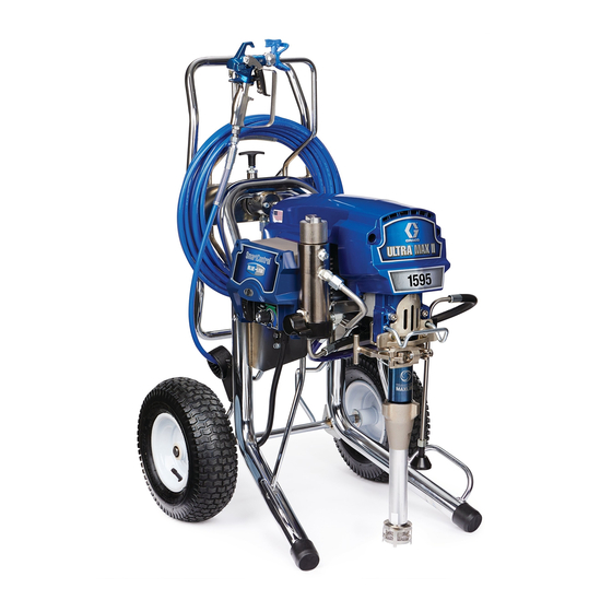
Page 10: 1095 / 1595 / Mark V Ironman Models
Component Identification 1095 / 1595 / Mark V IronMan Models: ti22935a Strainer Smart Control 3.0 Display Pump Amp Switch (not available on all units) ™ ON/OFF Switch ProConnect Pressure Control Rod Pull Feature Spray / Prime / Fast Flush Unit / Serial Tag Trigger Lock Drain Tube Filter... -
Page 11: Grounding
Grounding Grounding Do not modify plug! If it will not fit in outlet, have grounded outlet installed by a qualified electrician. Do not use an adapter. The equipment must be grounded to reduce the risk of static sparking and electric shock. Electric or static Power Requirements sparking can cause fumes to ignite or explode. -
Page 12: Pails
10/16 Amp Switch 10/16 Amp Switch Pails (Mark VII and Mark X units) Solvent and oil/based fluids: follow local code. Use only conductive metal pails, placed on a grounded sur- face such as concrete. Do not place pail on a nonconductive surface such as paper or cardboard which interrupts grounding continuity. -
Page 13: Pressure Relief Procedure
Pressure Relief Procedure Pressure Relief Procedure Follow the Pressure Relief Procedure whenever 4. Turn pressure to lowest setting. Trigger gun to you see this symbol. relieve pressure. This equipment stays pressurized until pressure is manually relieved. To help prevent serious injury from pressurized fluid, such as skin injection, splashing fluid and moving parts, follow the Pressure Relief Procedure when you stop spraying and before... -
Page 14: Setup
5. Check inlet strainer for clogs and debris. 1. All sprayers except ProContractor: Connect Graco airless hose to sprayer. Tighten securely. ti17608b 6. Fill throat packing nut with Graco TSL to prevent premature packing wear. Do this each time you spray. ti22875a If using the optional hopper, remove the nipple fit- ting from the filter. -
Page 15: Startup
Startup Startup 6. Hold gun against grounded metal flushing pail. Trig- ger gun and increase fluid pressure 1/2 turn. Flush 1 minute. 1. Perform Pressure Relief Procedure, page 13. 2. Turn pressure control to lowest pressure. ti22949a ti13670b High-pressure spray is able to inject toxins into the 3. -
Page 16: Switch Tip Installation
Switch Tip Installation Switch Tip Installation Spray 1. Spray test pattern. Increase pressure to eliminate heavy edges. Use smaller tip size if pressure adjust- ment can not eliminate heavy edges. 1. Perform Pressure Relief Procedure, page 13. ™ 2. Use spray tip (A) to insert OneSeal (B) into guard (C). -
Page 17: Fast Flush
Fast Flush (ProContractor and IronMan models only) Fast Flush ™ WatchDog Protection System (ProContractor and IronMan models only) (ProContractor and IronMan models only) Pump stops automatically when material pail is empty. To flush the hose and gun at an accelerated speed, per- form the following steps: To Activate: 1. -
Page 18: Proguard
ProGuard ProGuard This sprayer protects itself against high and low voltage. ProContractor and IronMan Models If the sprayer is plugged into a power source that is too low or too high the sprayer will stop operating. One of three error codes will be displayed: Error Definition Standard Models... -
Page 19: Hose Reel
Hose Reel Hose Reel (ProContractor models only) 3. Pull reel handle up and turn clockwise to reel in hose. Moving parts can pinch, cut or amputate fingers and other body parts. To avoid injury from moving parts, be sure to keep your head clear of hose reel while winding up hose. -
Page 20: Digital Tracking System (Procontractor And Ironman Models Only)
Digital Tracking System (ProContractor and IronMan models only) Digital Tracking System Job Gallons (ProContractor and IronMan models only) 1. Short press DTS button to move to Job Gallons (or liters x 10). Operation Main Menu Short press to move to next display. Press and hold (5 seconds) to change units or reset data. -
Page 21: Secondary Menu - Stored Data
Digital Tracking System (ProContractor and IronMan models only) Secondary Menu - Stored Data Short press DTS button. W-DOG scrolls past then OFF displays if watchdog switch is OFF. ON displays if Watch- dog switch is ON. Perform Pressure Relief, steps 1 - 4 if they have not already been done. -
Page 22: Cleanup
Cleanup Cleanup 5. Turn prime valve down to DRAIN position and allow flushing fluid to circulate until flushing fluid appears clear. 1. Perform Pressure Relief Procedure (page 13), steps 1 - 4. Remove tip guard from gun. NOTE: Use water for water-base material, mineral spirits for oil-base material, or other solvents recom- mended by manufacturer. - Page 23 Cleanup 9. Remove filters from gun and sprayer, if installed. 11. Wipe sprayer, hose and gun with a rag soaked in Clean and inspect. Install filters. water or mineral spirits. ti2776a ti15018a ti13454a 10. If flushing with water, flush again with mineral spir- its, or Pump Armor, to leave a protective coating to prevent freezing or corrosion.
-
Page 24: Troubleshooting
Troubleshooting Troubleshooting Mechanical/Fluid Flow Perform Pressure Relief Procedure; page 13. WHAT TO CHECK WHAT TO DO TYPE OF PROBLEM If check is OK, go to next check When check is not OK, refer to this column For units with display: Fault condition exists Determine fault correction from table, CODE XX is displayed. - Page 25 Troubleshooting WHAT TO CHECK WHAT TO DO TYPE OF PROBLEM If check is OK, go to next check When check is not OK, refer to this column Pump output is low Pump rod damage Repair pump. See pump manual. Low stall pressure Turn pressure knob fully clockwise.
- Page 26 Troubleshooting WHAT TO CHECK WHAT TO DO TYPE OF PROBLEM If check is OK, go to next check When check is not OK, refer to this column Air in pump or hose Check and tighten all fluid connections. Cycle Pump is difficult to prime pump as slowly as possible during priming.
-
Page 27: Electrical
Troubleshooting Electrical Control Board Status Light ProGuard Status Light Symptom: Sprayer does not run, stops running, or will not shut off. Perform Pressure Relief Procedure; page 13. 1. Plug sprayer into correct voltage, grounded outlet. For units without a display, see ProGuard (page 18). If 2. - Page 28 Troubleshooting TYPE OF PROBLEM WHAT TO CHECK HOW TO CHECK Sprayer does not run at all Check transducer or transducer Set sprayer to OFF and disconnect power to connections (control board is not sprayer. Display shows CODE 03 detecting a pressure signal). Check transducer and connections to control board.
- Page 29 Troubleshooting TYPE OF PROBLEM WHAT TO CHECK HOW TO CHECK Sprayer does not run at all Control is commanding motor to run Remove pump and try to run sprayer. If motor runs, but motor shaft does not rotate. check for locked or frozen pump or drive train. Display shows CODE 05 Possibly locked rotor condition, an If sprayer does not run, continue to step 2.
- Page 30 Set meter to ohms. Meter should read the proper resistance for each unit (see table below). Control board status light blinks 5 times repeatedly ti13140a Resistance Table: 695/240V Mark IV 0 ohms 795/120V Mark IV 2k ohms 1095/240V Mark V 3.9k ohms 1595/120V Mark V/MARK VII 6.2k ohms...
- Page 31 Set meter to ohms. Meter should read the proper resistance for each unit (see table below). Control board status light blinks 6 times repeatedly ti13140a Resistance Table: 695/240V Mark IV 0 ohms 795/120V Mark IV 2k ohms 1095/240V Mark V 3.9k ohms 1595/120V Mark V/MARK VII 6.2k ohms...
- Page 32 Troubleshooting TYPE OF PROBLEM WHAT TO CHECK HOW TO CHECK Sprayer does not run at all Excessive current protection Cycle power on and off. enabled Display shows CODE 12 Control board status light blinks 12 times repeatedly Sprayer does not run at all Check the connections above the Set sprayer to OFF and disconnect power to motor...
- Page 33 Troubleshooting Sprayer Will Not Run (See following page for steps) Remove control box cover. Turn sprayer ON. Observe control board status light on control board See Step 1. Do See Step 2. Do (see page 27). you have over you have over 100 VAC No light Repair or...
- Page 34 Troubleshooting STEP 1: STEP 2: Plug power cord in Plug power cord in 200-240V 200-240V and turn switch ON. and turn switch ON. Connect probes to Connect probes to on/off switch. Turn on/off switch. Turn meter to AC Volts. meter to AC Volts. STEP 3: STEP 4: Check motor thermal switch.
- Page 35 Troubleshooting Sprayer Will Not Shut Off 1. Perform Pressure Relief Procedure; page 13. 2. Remove control box cover so the control board Leave prime valve open and power switch OFF. status light can be viewed if available. Troubleshooting Procedure Plumb pressure gauge into paint Mechanical problem: See the proper hose, plug sprayer in, and turn power fluid pump manual for the sprayer for...
-
Page 36: Technical Data
Technical Data Technical Data 695 Sprayers U.S. Metric Sprayer Maximum Delivery North American Models 0.95 gpm 3.6 lpm International Models 0.75 gpm 2.8 lpm Maximum Tip Size 0.031 0.031 Fluid Outlet npsm 1/4 in. 1/4 in. Cycles 226 per gallon... - Page 37 Technical Data 795 Sprayers U.S. Metric Sprayer Maximum Delivery North American Models 1.1 gpm 4.2 lpm International Models 0.95 gpm 3.6 lpm Maximum Tip Size 0.033 0.033 Fluid Outlet npsm 1/4 in. 1/4 in. Cycles 195 per gallon 52 per liter Generator Minimum 5000 W 5000 W...
- Page 38 Technical Data 1095 Sprayers U.S. Metric Sprayer Maximum Delivery North American Models 1.2 gpm 4.5 lpm International Models 1.1 gpm 4.1 lpm Maximum Tip Size 0.035 0.035 Fluid Outlet npsm 1/4 in. 1/4 in. Cycles 123 per gallon 33 per liter Generator Minimum 5000 W 5000 W...
- Page 39 Technical Data 1595 Sprayers U.S. Metric Sprayer Maximum Delivery 1.35 gpm 5.1 lpm Maximum Tip Size 0.039 0.039 Fluid Outlet npsm 1/4 in. 1/4 in. Cycles 110 per gallon 29 per liter Generator Minimum 5000 W 5000 W 120V, A, Hz 20/15, 50/60 20/15, 50/60 Dimensions...
- Page 40 Technical Data Mark IV Sprayers U.S. Metric Sprayer Maximum Delivery North American Models 1.1 gpm 4.2 lpm International Models 0.95 gpm 3.6 lpm Maximum Tip Size North American Models 0.033 0.033 International Models 0.031 0.031 Fluid Outlet npsm 3/8 in. 3/8 in.
- Page 41 Technical Data Mark V Sprayers U.S. Metric Sprayer Maximum Delivery North American and UK Models 1.35 gpm 5.1 lpm International Models 1.2 gpm 4.5 lpm Maximum Tip Size North American and UK Models 0.039 0.039 International Models 0.035 0.035 Fluid Outlet npsm 3/8 in.
- Page 42 Technical Data Mark VII Sprayers U.S. Metric Sprayer Maximum Delivery 1.58 gpm 6.0 lpm Maximum Tip Size 0.041 in. 0.041 in. Fluid Outlet npsm 1/2 in. 1/2 in. Cycles 97 per gallon 26 per liter Generator Minimum 5000 W 5000 W 230V, A, Hz 16, 50/60 16, 50/60...
- Page 43 Technical Data Mark X Sprayers U.S. Metric Sprayer Maximum Delivery 2.1 gpm 8.0 lpm Maximum Tip Size 0.045 in. 0.045 in. Fluid Outlet npsm 1/2 in. 1/2 in. Cycles 70 per gallon 19 per liter Generator Minimum 5000 W 5000 W 230V, A, Hz 16, 50/60 Dimensions...
-
Page 44: Graco Standard Warranty
With the exception of any special, extended, or limited warranty published by Graco, Graco will, for a period of twelve months from the date of sale, repair or replace any part of the equipment determined by Graco to be defective.
Need help?
Do you have a question about the 695 and is the answer not in the manual?
Questions and answers