Table of Contents
Advertisement
Quick Links
Advertisement
Table of Contents

Subscribe to Our Youtube Channel
Related Manuals for Alcatel OMNISWITCH 7000


Summary of Contents for Alcatel OMNISWITCH 7000
- Page 1 ® OmniSwitch 7700/7800 Getting Started Guide 060130-10, Rev. G March 2005...
- Page 2 Warning. Only personnel knowledgeable in basic electrical and mechanical procedures should install or maintain this equipment. Lithium Batteries Caution. There is a danger of explosion if the Lithium battery in your chassis is incorrectly replaced. Replace the battery only with the same or equivalent type of battery recommended by the manufacturer. Dispose of used batteries according to the manufacturer’s instructions.
-
Page 3: Table Of Contents
Table of Contents OmniSwitch 7700/7800 ....1 Grounding Lug ......12 Installing the Network Interface (NI) and Features . - Page 4 Files and Directories Setting the Date and Time ....24 ....36 Setting Optional System Boot and Image Files .
- Page 5 Troubleshooting ......47 The WebView login screen does not display......47 The login screen displays, but my login attempt fails.
- Page 6 March 2005...
-
Page 7: Omniswitch 7700/7800
OmniSwitch 7700/7800 Refer to “Chassis Types” on page 2 for additional details on OS7700 and OS7800 switches. Both half duplex and full duplex are supported on all 10/100 n iS w it Ethernet ports; full duplex is supported on Gigabit Ethernet ports. -
Page 8: Chassis Types
For more information on Availability features, refer to your Hardware Users Guide, Switch Management Guide, and Network Configuration Guide. Chassis Types OmniSwitch 7700 The OmniSwitch 7700 is a 10-slot edge or small enterprise core switch. The OmniSwitch 7700 offers up to 192 10/100 Ethernet ports and can also be equipped with up to 96 Gigabit Ethernet ports. -
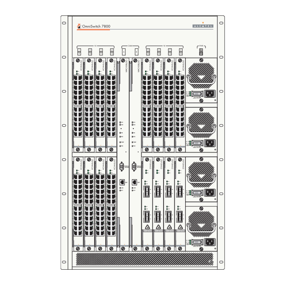
Page 9: Omniswitch 7800
OmniSwitch 7800 The OmniSwitch 7800 is an 18-slot switch designed for the medium enterprise core or large wiring closet. The OmniSwitch 7800 offers up to 384 10/100 Ethernet ports. Alternatively, it can be equipped with up to 192 Gigabit Ether- net ports. -
Page 10: Installing The Hardware
Installing the Hardware Items Required Electrical Requirements Grounding wrist strap (included) OmniSwitch 7700/7800 switches have the following general • electrical requirements: Phillips screwdriver • Each switch requires one grounded electrical outlet for • Flat-blade screwdriver each power supply installed in the chassis (up to three for •... -
Page 11: Weight Considerations
Unpacking and Installing the Switch Weight Considerations When fully-populated (i.e., with all CMM and NI modules and Unpacking the Chassis power supplies installed), the OmniSwitch 7700 weighs approximately 128 lbs (58 Kgs); the OmniSwitch 7800 weighs approximately 188 lbs (85 Kgs). To protect your switch components from electrostatic discharge (ESD) and physical damage, read all unpacking recommendations and instructions carefully before beginning. - Page 12 The overpack is the outer shell of the packaging. Lift the overpack straight up until it slides free from the rest of the packaging. This allows easy access to the chassis. 0 /1 /6 0 /2 5 .0 /7 .0 /3 Carefully remove the protective plastic from the switch chassis.
-
Page 13: Lifting The Chassis
Lifting the Chassis Once its weight has been reduced by removing the power 0 /1 /6 0 /2 5 .0 /7 .0 /3 supplies, the chassis can be lifted from the packaging material and moved to the location where it is to be installed (see important note below). -
Page 14: Rack-Mounting
Rack-Mounting Refer to the important guidelines below before installing the Rear. 6 inches minimum OmniSwitch chassis in a rack. at rear of chassis fan unit. Rack-mounting the chassis requires three people—two • people to hold the chassis and position it in the rack and a Sides. -
Page 15: Optional Rack-Mounting Hardware
Using two people, lift and position the chassis until the Once the screws at the bottom of each flange are rack-mount flanges are flush with the rack post. secure, install the remaining screws. Be sure that all screws are securely tightened. Align the holes in the flanges with the rack holes you marked in step 1. -
Page 16: Standalone
Installing Power Supplies Standalone The OmniSwitch 7700/7800 can be installed unmounted as a Next, reinstall the power supplies in the chassis power supply standalone unit. Be sure that the installation location is a bays by following the steps below. stable, flat surface that can accommodate the fully-populated weight of all switches being installed. - Page 17 Continue sliding the power supply back until the front Once the power cord is looped through the retainer, panel meets the front of the chassis. Do not force the plug the power cord connector into the power supply’s power supply into the bay. Otherwise you can damage the socket and then plug the power cord into an easily-acces- connectors.
-
Page 18: Using The Grounding Wrist Strap And Chassis
Using the Grounding Wrist Strap and Note. The grounding lug diagram at left is a general diagram only. It is intended to show the location of the Chassis Grounding Lug grounding lug. No NI modules or CMMs should be Because electrostatic discharge (ESD) can damage switch installed in your chassis at this time. -
Page 19: Installing The Network Interface (Ni) And Chassis Management Modules (Cmms)
Installing the Network Interface (NI) and To install an NI or CMM module, follow the steps below. Chassis Management Modules (CMMs) Note. To further reduce exposure to electrostatic discharge Once you are properly grounded, you may begin installing the (ESD) and physical damage, do not remove more than one Network Interface (NI) and CMM(s). - Page 20 The module should slide in easily. Do not force the Once the module is firmly seated, secure the module to module into the slot. If any resistance is encountered, the chassis by tightening the two captive screws. Be sure ensure the module is aligned properly in the card guide. not to overtighten the captive screws.
-
Page 21: Installing Gbic Connectors
Caution. Do not force the GBIC into the slot. If the GBIC Installing GBIC Connectors does not slide easily into position, verify that the GBIC grooves are aligned properly. Forcing the GBIC into the If you are installing an OS7-GNI-U2 module, you must install slot can damage the unit, as well as components on your Gigabit Interface Converters (GBICs) as required. -
Page 22: Blank Cover Plates
Blank Cover Plates Note. The diagram below is a representation only; the physical appearance of the actual MiniGBIC may vary. Blank cover plates are factory-installed in the chassis and are used to cover empty CMM and NI slots, as well as empty GNI Module power supply bays. -
Page 23: Connections And Cabling
Connections and Cabling Once your switch is properly installed, you should connect all Serial Connection Default Settings network and management cables required for your network applications. Connections may include: The factory default settings for the serial connection are as follows: Serial cable to the console port •... -
Page 24: Ethernet Management Port (Emp) Cable Requirements
Refer to the diagram below for console/modem port and EMP Ethernet Management Port (EMP) Cable Requirements locations. There are specific cable type requirements (i.e., straight- through or crossover) based on the location of the Ethernet n i S t c h Management Port (EMP) and the type of device to which it is connecting. -
Page 25: Booting The Switch
Booting the Switch NI OK2 Blinking Green Now that you have installed the switch components and connected all required cables, you can boot the switch. To boot Power Supply AC OK Solid Green the switch, simply turn the on/off switch for all installed power Power Supply DC OK Solid Green supplies to the on ( | ) position. -
Page 26: Your First Login Session
Important. You must be connected to the switch via the followed by the CLI command prompt: console port before initiating your first login session. Welcome to the Alcatel OmniSwitch 7000 Software Version 5.1.5: April 30, 2004. Copyright(c), 1994-2003 Alcatel Internetworking, Inc. -
Page 27: Setting Ip Address Information For The Emp
More Information On User Accounts. A user account Enter modify boot parameters at the CLI prompt. The includes a login name, password, and user privileges. boot prompt displays: Privileges determine whether the user has read or write Boot > access to the switch and which commands the user is authorized to execute. -
Page 28: Unlocking Session Types
Unlocking Session Types Access to the EMP. By default, only devices in the same subnet as the EMP will be able to manage the switch through that port. For information on allowing devices in Security is a key feature on OmniSwitch 7700/7800 switches. other subnets to manage the switch via the EMP, refer to As a result, when you access the switch for the first time, you the Hardware Users Guide. -
Page 29: How Many Sessions Are Allowed
Changing the Login Password To unlock WebView (HTTP) sessions only, enter the follow- ing command: Change the login password for admin user sessions by follow- -> aaa authentication http local ing the steps below: You cannot specify more than one session type in a single Be sure that you have logged into the switch as user command line. -
Page 30: Setting The System Time Zone
Setting the Date and Time All subsequent login sessions—including those through the console port—will require the new password in order to access the switch. Set the current time for the switch by entering system time, followed by the current time in hh:mm:ss. For example: User Accounts. -
Page 31: Setting Optional System Information
Setting Optional System Specifying a System Name Information The system name is a simple, user-defined text description for This section provides information on configuring optional the switch. system parameters, including: To specify a system name, enter system name, followed by a the switch’s administrative contact text description of up to 254 characters. -
Page 32: Viewing Your Changes
Viewing Your Changes Modifying the Serial Connection Settings To view your current changes, enter show system at the CLI prompt. The switch’s serial connection defaults are listed on page If you wish to modify the default serial connection settings Saving Your Changes (i.e., baud rate, parity, data bits, and stop bits), refer to the following steps. - Page 33 To change the parity value, enter boot serialparity, You can save your changes to the boot.params file by followed by the desired parity value. Options include none entering commit file at the boot prompt: (default), even, and odd. For example: Boot >...
- Page 34 Return to the CLI prompt by entering exit at the boot prompt. This completes the initial setup process. Your OmniSwitch 7700/7800 switch is now ready for additional configuration and network operation. Refer to the following sections for more information on using your switch, as well as additional built-in features.
-
Page 35: Cli Basics
CLI Basics The Command Line Interface (CLI) allows you to configure Note. The software supports vt100 terminal emulation; and monitor your switch by entering single-line commands. CLI assistance features may be limited if your terminal The CLI can be accessed through terminal or Telnet sessions. emulation software is using a setting other than vt100. -
Page 36: Command Line (?) Help
Command Line (?) Help Partial Keyword Completion The CLI provides additional help in the form of the question The CLI has a partial keyword recognition feature. Instead of mark (?) character. The ? character provides information that typing an entire keyword, you can type only the minimum helps you build your command syntax. -
Page 37: Inserting Characters
Inserting Characters Prefix Recognition To insert a character between characters that are already typed, Prefix recognition is a CLI feature that reduces redundant use the Left and Right Arrow keys to place the cursor into command line entry by storing commonly-used prefix infor- position, then type the new character. -
Page 38: Prefix Prompt
Prefix Prompt 11 ip load dvmrp 12 show arp You can set the CLI to display the current command prefix as 13 show history the command prompt by entering the following command: Note that the most recent commands are displayed lower in the ->... -
Page 39: Command Logging
Command Logging When command logging is enabled via the command-log enable syntax, a file called command.log is automatically OmniSwitch 7700/7800 switches provide command logging. created in the switch’s /flash directory. Once enabled, configu- This feature allows users to record up to 100 of the most recent ration commands entered on the command line will be commands entered via Telnet and console sessions. -
Page 40: Common Cli Commands
Common CLI Commands show cmm Displays basic hardware and status information for a stand- The following table lists some basic CLI commands that will alone switch, or for the primary help you get acquainted with the CLI interface. Enter each or secondary switches installed command exactly as shown. -
Page 41: Offline Configuring
Offline Configuring Scheduling a Configuration File to be Applied at a Later Time You can configure OmniSwitch 7700/7800 switches using an You can apply a file to the switch immediately, or you can ASCII-based text file. This is referred to as offline configur- schedule a file to be applied either at a specific date and time ing. -
Page 42: Files And Directories
Files and Directories Boot and Image Files boot.cfg File The boot.cfg file stores your network configuration parame- Although the switch’s flash memory can contain many file ters. When you first boot the switch, no boot.cfg file is types (e.g., log and snapshot files), there are three specific file present. -
Page 43: Image Files
Image Files Feni.img Provides support for 10/100, Fast Ether- net, and Gigabit Ethernet. Image files (those files with .img extensions) contain execut- Fdiag.img Provides enhanced hardware diagnostics able code that provides support for the system, NI modules, for the switch. and network functions. -
Page 44: Working And Certified Directories
Working and Certified configuring your switch are saved to the boot.cfg file in the /flash/working directory. Directories Once the /flash/working directory’s configuration and image files are road-tested and considered valid and reliable for your OmniSwitch 7700/7800 switches are shipped with 32 MB of network, they can be copied to the /flash/certified directory. -
Page 45: How Can I Tell Which Directory The Switch Is Currently Using
tested, the contents of the /flash/working directory can be How can I tell which directory the switch is currently using? copied to the /flash/certified directory via the copy working certified command. When you first boot the switch, the /flash/working directory is What happens when the switch boots? used;... -
Page 46: Working And Certified Are Different
Working and Certified Are Different My Working and Certified directories are different. Can I force a reboot from the Working directory? If the software in the /flash/working directory differs even slightly from the software in the /flash/certified directory, the Yes. If its configuration and image files are known to be reli- switch will automatically run from the /flash/certified direc- able, you can override the default and initiate a reboot from the tory... -
Page 47: Loading Software
Loading Software The following section describes the procedure for loading new Using your FTP client or the CLI’s rm command, release software to your switch. Note that the procedure varies delete all .img files from the /flash/working directory. slightly for non-redundant (single CMM) and redundant (dual You can use the asterisk (*) wildcard to delete all .img CMM) configurations. -
Page 48: Redundant Configurations
Redundant Configurations Use the install command after the software files have been transferred to the switch via FTP. For example: Verify that the OK1 LED is solid green and the OK2 -> install /flash/working/*.img LED is flashing green on both the primary and secondary CMM modules. - Page 49 Using your FTP client, upload all required .img files During this reload, the secondary CMM takes over the primary from the new software release to the primary CMM’s role and the switch runs from the /flash/working directory /flash/working directory. (i.e., the new release software) until the next system reboot. Meanwhile, the software in the /flash/certified directory Use the install command after the software files have remains unchanged and available as a last known good version...
-
Page 50: Using Webview
Using WebView Required Image Files The switch can be configured and monitored using WebView, Alcatel’s Web-based device management tool. WebView soft- ware is pre-installed in the switch; you are not required to load In order to access WebView, the following image files must be additional software. -
Page 51: Logging In To Webview
Logging In to WebView Remember, if you have already changed the user name and password for your switch, be sure to use the new information. If you have not changed your user name or password, the Note. Before attempting to establish a WebView session, factory defaults are admin and switch, respectively. - Page 52 Navigate the application by clicking on the “Configuration Refine your navigation by selecting “Configuration Options” Group” buttons in the left-hand toolbar for each group from the items displayed in the grey, horizon- tal navigation bar: “Configuration Options” Toolbar. (In this case, the option “Device”...
-
Page 53: Online Help
Online Help Troubleshooting The WebView login screen does not display. General online help is available through the main Help link located in the top WebView banner: This suggests either a physical or network connection issue. Try the following options: Be sure that you have a good physical Ethernet cable •... -
Page 54: Hardware Basics
Hardware Basics Chassis Slot Numbering The term “slot” refers to the position at which a module is installed in the chassis. CMM slot positions are designated as OmniSwitch 7800 Slots A and B. For the OS7700, NI slot numbers range from 1 to 8. -
Page 55: Chassis Management Module (Cmm)
CMM Redundancy Chassis Management Module (CMM) CMM redundancy is an important resiliency feature. For CMM redundancy, two fully-operational CMM modules must The Chassis Management Module (CMM) is the management be installed in the chassis at all times. unit for OmniSwitch 7700/7800 switches. In its role as the management unit, the CMM provides key system services, When two CMMs are running in the switch, one CMM has the including:... -
Page 56: Cmm Slot Locations
CMM Slot Locations CMM Slot A CMM Slot B CMM Slot A CMM Slot B OmniSwitch 7700 OmniSwitch 7800 Hardware Basics March 2005... -
Page 57: Cmm Front Panel
CMM Front Panel Module Status LEDs OK1. Hardware Status. Displays solid green when powered on and the CMM has passed hardware diagnostic tests. Displays solid amber when powered on and the CMM has failed hardware diagnos- tic tests. OK2. Software Status. Blinks green when the CMM is operational. Displays solid amber when a system software failure occurs. -
Page 58: Network Interface (Ni) Modules
GNI Modules Network Interface (NI) Modules The Gigabit Ethernet Network Interface (GNI) modules provide up to twelve 1000 Mbps (1 Gbps) connections per The following section outlines front panel information for module. GNI modules can be used for backbone connections Network Interface (NI) modules, including LED and port in networks where Gigabit Ethernet is used as the backbone descriptions. -
Page 59: Gigabit Interface Converters (Gbics)
Gigabit Interface Converters (GBICs) Miniature Gigabit Interface Converters (MiniGBICs) The OS7-GNI-U2 module provides two Gigabit Interface Converters (GBIC) slots. A GBIC is a Gigabit Ethernet port The OS7-GNI-U12 module provides 12 MiniGBIC slots. A module that is hot-pluggable—i.e., it can be installed or MiniGBIC is a Gigabit Ethernet port module that is hot-plug- removed while the GNI is powered on and operating without gable—i.e., it can be installed or removed while the GNI is... -
Page 60: Os7-Eni-C24 Front Panel
OS7-ENI-C24 Front Panel Module Status LEDs OK1. Hardware Status. Displays solid green when powered on and the ENI has passed hardware diagnostic tests. Dis- plays solid amber when powered on and the ENI has failed hardware diagnostic tests. Module Status LEDs OK2. -
Page 61: Os7-Eni-Fm12 Front Panel
OS7-ENI-FM12 Front Panel Module Status LEDs OK1. Hardware Status. Displays solid green when powered on and the ENI has passed hardware diagnostic tests. Displays solid amber when powered on and the ENI Module has failed hardware diagnostic tests. Status LEDs OK2. -
Page 62: Os7-Eni-P24 Front Panel
OS7-ENI-P24 Front Panel OK1. Hardware Status. Displays solid green when powered on and the ENI has passed hardware diagnostic tests. Displays solid amber when powered on and the ENI has failed hardware diagnostic tests. OK2. Software Status. Blinks green when Module Status the ENI is operational and has successfully... -
Page 63: Os7-Gni-U2 Front Panel
OS7-GNI-U2 Front Panel Module Status LEDs OK1. Hardware Status. Displays solid green when powered on and the GNI has passed hardware diagnostic tests. Displays solid amber when powered on and the GNI has failed hardware diagnostic tests. Module Status OK2. Software Status. Blinks green when LEDs the GNI is operational and has successfully loaded software. -
Page 64: Os7-Gni-U12 Front Panel
OS7-GNI-U12 Front Panel Module Status LEDs OK1. Hardware Status. Displays solid green when powered on and the GNI has passed hardware diagnostic tests. Displays solid amber when powered on and the GNI has failed hardware diagnostic tests. Module Status OK2. Software Status. Blinks green when LEDs the GNI is operational and has successfully loaded software. -
Page 65: Os7-Gni-C12 Front Panel
OS7-GNI-C12 Front Panel Module Status LEDs OK1. Hardware Status. Displays solid green when powered on and the GNI has passed hardware diagnostic tests. Displays solid amber when powered on and the GNI has failed hardware diagnostic tests. Module Status OK2. Software Status. Blinks green when LEDs the GNI is operational and has successfully loaded software. - Page 66 that accompanies this Getting Started Guide contains OmniSwitch 7700/7800/8800 Switch Management • comprehensive Alcatel user documentation, including the Guide following manuals: Includes procedures for readying an individual switch OmniSwitch 7700/7800 Getting Started Guide for integration into a network. Topics include the soft- •...
-
Page 67: User Documentation On Cd
User Documentation on CD March 2005 User Documentation on CD... -
Page 68: General Information
OmniSwitch 7700/7800/8800 Advanced Routing If you cannot locate a button with the document image behind • Configuration Guide the binoculars (as shown), then the global search feature is not available in the version of Acrobat Reader you are currently Includes network configuration procedures and using.
Need help?
Do you have a question about the OMNISWITCH 7000 and is the answer not in the manual?
Questions and answers