
Related Manuals for Alcatel OS6850-P48


Summary of Contents for Alcatel OS6850-P48
- Page 1 Part No. 060209-10, Rev. K June 2011 OmniSwitch 6850/6850E Series Hardware Users Guide www.alcatel-lucent.com...
- Page 2 This user guide documents OmniSwitch 6850/6850E Series hardware, including The specifications described in this guide are subject to change without notice. Copyright © 2011 by Alcatel-Lucent. All rights reserved. This document may not be reproduced in whole or in part without the express written permission of Alcatel-Lucent.
-
Page 3: Table Of Contents
Contents Contents About This Guide Supported Platforms ... ix Who Should Read this Manual? ... xi When Should I Read this Manual? ... xi What is in this Manual? ... xi What is Not in this Manual? ... xi How is the Information Organized? ... xii Documentation Roadmap ... - Page 4 10/100/1000 LEDs ...2-54 100/1000 SFP LEDs ...2-54 10000 XFP1 LEDs ...2-54 10000 XFP2 LEDs ...2-54 Rear Panel ...2-55 Mounting the Switch ...2-56 Airflow Considerations ...2-56 Chassis Airflow ...2-57 Blank Cover Panels ...2-58 Installation Options ...2-59 Installing the Switch on a Tabletop or Bench ...2-59 Rack-Mounting the Switch ...2-60 Installing and Removing Combo Port SFPs ...2-61 Setting Up a Stacked Configuration ...2-62...
- Page 5 Contents OmniSwitch 6850E-P48 ...3-17 OmniSwitch 6850E-P48 Rear Panel ...3-18 OS6850E-P48 Specifications ...3-19 OmniSwitch 6850E-48X ...3-20 OmniSwitch 6850E-48X Rear Panel ...3-21 OS6850E-48X Specifications ...3-22 OmniSwitch 6850E-P48X ...3-23 OmniSwitch 6850E-P48X Rear Panel ...3-24 OS6850E-P48X Specifications ...3-25 OmniSwitch 6850E-U24X ...3-26 OmniSwitch 6850E-U24X Rear Panel ...3-27 OS6850E-U24X Specifications ...3-28 OS6-XNI-U2 Module ...3-29 OmniSwitch 6850E Port Numbering ...3-30...
- Page 6 Chapter 5 Managing Power over Ethernet (PoE) In This Chapter ...5-2 Power over Ethernet Specifications ...5-3 Viewing PoE Power Supply Status ...5-4 Configuring Power over Ethernet Parameters ...5-5 Power over Ethernet Defaults ...5-5 Understanding and Modifying the Default Settings ...5-5 PoE Class Detection ...5-5 Setting the PoE Operational Status ...5-6 Configuring the Total Power Available to a Port ...5-6...
- Page 7 Contents Hot-Swapping Modules In a Stack ...6-27 Removing Switches from an Existing Stack ...6-27 Inserting Switches Into an Existing Stack ...6-27 Merging Stacks ...6-28 Reloading Switches ...6-29 Reloading the Primary Management Module ...6-29 Reloading the Secondary Management Module ...6-31 Reloading Switches with Idle Roles ...6-33 Reloading Switches in Pass-Through Mode ...6-33 Reloading All Switches in a Stack ...6-34 Software Synchronization During a Full Reload ...6-34...
- Page 8 Contents Advertencia de instalación ... A-12 Advertencia de radiación láser invisible ... A-12 Advertencia de la batería de litio ... A-12 Advertencia sobre la tensión de operación ... A-12 Advertencia sobre la desconexión de la fuente ... A-12 Advertencia sobre una apropiada conexión a tierra ... A-13 Leer “información importante de seguridad”...
-
Page 9: About This Guide
This OmniSwitch 6850/6850E Series Hardware Users Guide describes your switch hardware components and basic switch hardware procedures. Supported Platforms This information in this guide applies to the following products: • OmniSwitch 6850-24/24L/P24/P24L/24X/P24X • OmniSwitch 6850-48/48L/P48/P48L/48X/P48X • OmniSwitch 6850-U24X • OmniSwitch 6850E-24/P24/24X/P24X •... - Page 10 Supported Platforms Unsupported Platforms The information in this guide does not apply to the following products: • OmniSwitch (original version with no numeric model name) • OmniSwitch 6600 Family • OmniSwitch 6800 Series • OmniSwitch 7700 • OmniSwitch 7800 • OmniSwitch 8800 •...
-
Page 11: Who Should Read This Manual
About This Guide Who Should Read this Manual? The audience for this users guide is network administrators and IT support personnel who need to config- ure, maintain, and monitor switches and routers in a live network. However, anyone wishing to gain knowledge on the OmniSwitch 6850/6850E Series hardware will benefit from the material in this guide. -
Page 12: How Is The Information Organized
How is the Information Organized? How is the Information Organized? This users guide provides an overview of OmniSwitch 6850/6850E Series switches, an overview and procedures for setting up and managing the switches, an overview and procedures for managing Power over Ethernet (PoE), and an overview and procedures for managing stacks. Documentation Roadmap The OmniSwitch user documentation suite was designed to supply you with information at several critical junctures of the configuration process.The following section outlines a roadmap of the manuals that will... - Page 13 About This Guide Stage 3: Integrating the Switch Into a Network Pertinent Documentation: OmniSwitch AOS Release 6 Network Configuration Guide OmniSwitch AOS Release 6 Advanced Routing Configuration Guide When you are ready to connect your switch to the network, you will need to learn how the OmniSwitch implements fundamental software features, such as 802.1Q, VLANs, and Spanning Tree.
-
Page 14: Related Documentation
Includes SFP and XFP transceiver specifications and product compatibility information. • Technical Tips, Field Notices Includes information published by Alcatel-Lucent’s Customer Support group. • Release Notes Includes critical Open Problem Re, feature exceptions, and other important information on the features supported in the current release and any limitations to their support. -
Page 15: Published / Latest Product Documentation
About This Guide Published / Latest Product Documentation All user guides are included on the Alcatel-Lucent public website. This website also includes user guides for other Alcatel-Lucent Enterprise products. The latest user guides can be found on our website at: http://enterprise.alcatel-lucent.com/?dept=UserGuides&page=Portal... - Page 16 Technical Support About This Guide page xvi OmniSwitch 6850/6850E Series Hardware Users Guide June 2011...
-
Page 17: Omniswitch 6850/6850E Series
1 OmniSwitch 6850/6850E The OmniSwitch 6850/6850E Series are an advanced fixed configuration family of stackable Ethernet switches. These switches provide wire rate layer-2 forwarding and layer-3 routing with advanced services, effective availability, resiliency, and security features and are ideal for the following network applications: •... -
Page 18: Availability Features
Availability Features Availability Features The switch provides a broad variety of availability features. Availability features are hardware and software-based safeguards that help to prevent the loss of data flow in the unlikely event of a subsystem failure. In addition, some availability features allow users to maintain or replace hardware components without powering off the switch or interrupting switch operations. -
Page 19: Hot Swapping
OmniSwitch 6850/6850E Series Hot Swapping Hot swapping refers to the action of adding, removing, or replacing components without powering off switches or disrupting other components.This feature facilitates hardware upgrades and maintenance and allows users to easily replace components in the unlikely event of hardware failure. The following hardware components can be hot swapped: •... - Page 20 Availability Features OmniSwitch 6850/6850E Series page 1-4 OmniSwitch 6850/6850E Series Hardware Users Guide June 2011...
-
Page 21: Omniswitch 6850 Series Chassis And Hardware Components
• OmniSwitch 6850-24X (OS6850-24X) • OmniSwitch 6850-48X (OS6850-48X) • OmniSwitch 6850-P24 (OS6850-P24) • OmniSwitch 6850-P48 (OS6850-P48) • OmniSwitch 6850-P24X (OS6850-P24X) • OmniSwitch 6850-P48X (OS6850-P48X) OmniSwitch 6850/6850E Series Hardware Users Guide Components 24-port 10/100 48-port 10/100 24-port 10/100 Power over Ethernet (PoE) -
Page 22: Chapter 2 Omniswitch 6850 Series Chassis And Hardware Components
This chapter includes detailed information on these chassis types. Topics include: • OmniSwitch 6850 Series chassis descriptions • Technical specifications • Switch mounting • Booting OmniSwitch 6850 Series switches • Power cords, console port, and pinout specifications • OmniSwitch 6850 Series power supplies •... -
Page 23: Omniswitch 6850-24L
Console port (RJ-45) • USB port Note. The 20 (non-combo) 10/100Base-T on the OmniSwitch 6850-24L can be upgraded to 10/100/1000Base-T. Please contact your Alcatel-Lucent representative for more information. OmniSwitch 6850/6850E Series Hardware Users Guide OmniSwitch 6850-24L June 2011 page 2-3... - Page 24 OmniSwitch 6850-24L Refer to the illustration below for more front panel information. For detailed LED descriptions, refer to page 2-53. For information on the chassis rear panel, refer to USB Port High speed USB port, which can be used for quick upgrades. OmniSwitch 6850-24L Console 10/100 Mbps and 10/100/1000Mbps...
- Page 25 OmniSwitch 6850 Series Chassis and Hardware Components OS6850-24L Specifications Total unshared 10/100Base-T per switch (1–20) Total shared 10/100/1000Base-T combo per switch (21–24) Total combo 1000Base-X combo SFP connectors per switch (21–24) Total 10/100Base-T per stack Total combo SFP connectors per stack Power Flash memory size...
- Page 26 OmniSwitch 6850-24L OS6850-24L Specifications Maximum cable distance (RJ-45) page 2-6 OmniSwitch 6850 Series Chassis and Hardware Components 100 meters OmniSwitch 6850/6850E Series Hardware Users Guide June 2011...
-
Page 27: Omniswitch 6850-48L
Console port (RJ-45) • USB port Note. The 44 (non-combo) 10/100Base-T on the OmniSwitch 6850-48L can be upgraded to 10/100/1000Base-T. Please contact your Alcatel-Lucent representative for more information. OmniSwitch 6850/6850E Series Hardware Users Guide OmniSwitch 6850-48L June 2011 page 2-7... - Page 28 OmniSwitch 6850-48L Refer to the illustration below for more front panel information. For detailed LED descriptions, refer to page 2-53. For information on the chassis rear panel, refer to Status and Slot Indicator LEDs For detailed information on OS6850-48L status and slot indicator LEDs, refer to 2-53.
- Page 29 OmniSwitch 6850 Series Chassis and Hardware Components OS6850-48L Specifications Total unshared 10/100Base-T per switch (5–48) Total shared 10/100/1000Base-T combo per switch (1–4) Total combo SFP connectors per switch Total 10/100Base-T per stack Total combo SFP connectors per stack Power Flash memory size RAM memory size Overall Width (rack-mount flanges included)
-
Page 30: Omniswitch 6850-P24L
• USB port Note. The 20 (non-combo) 10/100Base-T PoE on the OmniSwitch 6850-P24L can be upgraded to 10/100/ 1000Base-T PoE. Please contact your Alcatel-Lucent representative for more information. page 2-10 OmniSwitch 6850 Series Chassis and Hardware Components OmniSwitch 6850/6850E Series Hardware Users Guide... - Page 31 OmniSwitch 6850 Series Chassis and Hardware Components Refer to the illustration below for more front panel information. For detailed LED descriptions, refer to page 2-53. For information on the chassis rear panel, refer to USB Port High speed port, which can be used for quick upgrades.
- Page 32 OmniSwitch 6850-P24L OS6850-P24L Specifications Total unshared 10/100Base-T PoE per switch (1–20) Total shared 10/100/1000Base-T combo PoE per switch (21–24) Total combo 1000Base-X combo SFP connectors per switch (21–24) Total 10/100Base-T PoE per stack Total combo SFP connectors per stack Power Flash memory size RAM memory size Overall Width (rack-mount...
- Page 33 OmniSwitch 6850 Series Chassis and Hardware Components OS6850-P24L Specifications Cable supported (RJ-45) Power supplied to port Maximum cable distance (RJ-45) OmniSwitch 6850/6850E Series Hardware Users Guide 10BaseT: unshielded twisted-pair (UTP) 100BaseTX: unshielded twisted-pair (UTP), Category 5, EIA/TIA 568 or shielded twisted-pair (STP), Category 5, 100 ohm 1000BaseT: unshielded twisted-pair (UTP), Category 5e 15.4 watts per port 100 meters...
-
Page 34: Omniswitch 6850-P48L
• USB port Note. The 44 (non-combo) 10/100Base-T PoE on the OmniSwitch 6850-P48L can be upgraded to 10/100/ 1000Base-T PoE. Please contact your Alcatel-Lucent representative for more information. page 2-14 OmniSwitch 6850 Series Chassis and Hardware Components OmniSwitch 6850/6850E Series Hardware Users Guide... - Page 35 OmniSwitch 6850 Series Chassis and Hardware Components Refer to the illustration below for more front panel information. For detailed LED descriptions, refer to page 2-53. For information on the chassis rear panel, refer to Status and Slot Indicator LEDs For detailed information on OS6850-P48L’s status and slot indica- tor LEDs, refer to page...
- Page 36 OmniSwitch 6850-P48L OS6850-P48L Specifications Total unshared 10/100Base-T PoE per switch (5–48) Total shared 10/100/1000Base-T combo PoE per switch (1–4) Total combo 1000Base-X combo SFP connectors per switch Total 10/100Base-T PoE per stack Total combo SFP connectors per stack Power Flash memory size RAM memory size Overall Width (rack-mount flanges included)
- Page 37 OmniSwitch 6850 Series Chassis and Hardware Components OS6850-P48L Specifications Cable supported (RJ-45) Power supplied to port Maximum cable distance (RJ-45) OmniSwitch 6850/6850E Series Hardware Users Guide 10BaseT: unshielded twisted-pair (UTP) 100BaseTX: unshielded twisted-pair (UTP), Category 5, EIA/TIA 568 or shielded twisted-pair (STP), Category 5, 100 ohm 1000BaseT: unshielded twisted-pair (UTP), Category 5e 15.4 watts per port 100 meters...
-
Page 38: Omniswitch 6850-U24X
OmniSwitch 6850-U24X OmniSwitch 6850-U24X The OmniSwitch 6850-U24X is an edge/workgroup switch offering 24 1000Base-X SFP connectors, two (2) 10 Gigabit XFP connectors, as well as four combo individually configurable to 10/100/1000Base-T. The front panel of the OS6850-U24X chassis contains the following major components: •... - Page 39 OmniSwitch 6850 Series Chassis and Hardware Components Refer to the illustration below for more front panel information. For detailed LED descriptions, refer to page 2-53. For information on the chassis rear panel, refer to 1000Mbps SFP USB Port The OS6850-U24X provides 22 non-combo SFP con- High speed USB port, which nectors for 1000Base-X SFP connectors (1–22) and 2 can be used for quick upgrades.
- Page 40 OmniSwitch 6850-U24X OS6850-U24X Specifications Total unshared 1000Base-X SFP connectors per switch (1–22) Total shared 1000Base-X SFP connectors per switch (23–24) Total combo10/100/1000Base-T per switch (23–24) Total XFP Connectors (25–26) Total 1000Base-X SFP connec- tors per stack Total combo 10/100/1000Base- T per stack Power Flash memory size RAM memory size...
- Page 41 OmniSwitch 6850 Series Chassis and Hardware Components OS6850-U24X Specifications Cable supported (RJ-45) Maximum cable distance (RJ-45) OmniSwitch 6850/6850E Series Hardware Users Guide 10BaseT: unshielded twisted-pair (UTP) 100BaseTX: unshielded twisted-pair (UTP), Category 5, EIA/TIA 568 or shielded twisted-pair (STP), Category 5, 100 ohm 1000BaseT: unshielded twisted-pair (UTP), Category 5e 100 meters June 2011...
-
Page 42: Omniswitch 6850-24
OmniSwitch 6850-24 OmniSwitch 6850-24 The OmniSwitch 6850-24 is a stackable edge/workgroup switch offering 20 unshared 10/100/1000 Base- T, as well as four combo individually configurable to be 10/100/1000 Base-T or 1000 Base-X high speed connections. The front panel of the OS6850-24 chassis contains the following major components: •... - Page 43 OmniSwitch 6850 Series Chassis and Hardware Components Refer to the illustration below for more front panel information. For detailed LED descriptions, refer to page 2-53. For information on the chassis rear panel, refer to USB Port High speed USB port, which can be used for quick upgrades.
- Page 44 OmniSwitch 6850-24 OS6850-24 Specifications Total unshared 10/100/000Base- T per switch (1–20) Total shared 10/100/1000Base-T combo per switch (21–24) Total combo 1000Base-X combo SFP connectors per switch (21–24) Total 10/100/1000Base-T per stack Total combo SFP connectors per stack Power Flash memory size RAM memory size Overall Width (rack-mount flanges included)
- Page 45 OmniSwitch 6850 Series Chassis and Hardware Components OS6850-24 Specifications Maximum cable distance (RJ-45) OmniSwitch 6850/6850E Series Hardware Users Guide 100 meters June 2011 OmniSwitch 6850-24 page 2-25...
-
Page 46: Omniswitch 6850-48
OmniSwitch 6850-48 OmniSwitch 6850-48 The OmniSwitch 6850-48 is a stackable edge/workgroup switch offering 44 unshared 10/100/1000Base-T, as well as four combo individually configurable to 10/100/1000Base-T or 1000Base-X high speed connec- tions. The front panel of the OS6850-48 chassis contains the following major components: •... - Page 47 OmniSwitch 6850 Series Chassis and Hardware Components Refer to the illustration below for more front panel information. For detailed LED descriptions, refer to page 2-53. For information on the chassis rear panel, refer to Status and Slot Indicator LEDs For detailed information on OS6850-48 status and slot indicator LEDs, refer to page 2-53.
- Page 48 OmniSwitch 6850-48 OS6850-48 Specifications Total unshared 10/100/ 1000Base-T per switch (5–48) Total shared 10/100/1000Base-T combo per switch (1–4) Total combo SFP connectors per switch (1–4) Total 10/100/1000Base-T per stack Total combo SFP connectors per stack Power Flash memory size RAM memory size Overall Width (rack-mount flanges included) Chassis Width (rack-mount...
- Page 49 OmniSwitch 6850 Series Chassis and Hardware Components OS6850-48 Specifications Maximum cable distance (RJ-45) OmniSwitch 6850/6850E Series Hardware Users Guide 100 meters June 2011 OmniSwitch 6850-48 page 2-29...
-
Page 50: Omniswitch 6850-24X
OmniSwitch 6850-24X OmniSwitch 6850-24X The OmniSwitch 6850-24X is a stackable edge/workgroup switch offering 20 unshared 10/100/1000 Base- T Power over, two (2) 10 Gigabit XFP connectors, as well as four combo individually configurable to 10/ 100/1000 Base-T or 1000 Base-X high speed connections. The front panel of the OS6850-24X chassis contains the following major components: •... - Page 51 OmniSwitch 6850 Series Chassis and Hardware Components Refer to the illustration below for more front panel information. For detailed LED descriptions, refer to page 2-53. For information on the chassis rear panel, refer to 10/100/1000Mbps USB Port The OS6850-24X provides 20 fixed 10/100/1000BaseT High speed USB port, which non-combo (1–20) and 4 fixed can be used for quick upgrades.
- Page 52 OmniSwitch 6850-24X OS6850-24X Specifications Total unshared 10/100/ 1000Base-T per switch (1–20) Total shared 10/100/1000Base-T combo per switch (21–24) Total combo 1000Base-X combo SFP connectors per switch (21– Total XFP Connectors (25–26) Total 10/100/1000Base-T per stack Total combo SFP connectors per stack Power Flash memory size...
- Page 53 OmniSwitch 6850 Series Chassis and Hardware Components OS6850-24X Specifications Cable supported (RJ-45) Maximum cable distance (RJ-45) OmniSwitch 6850/6850E Series Hardware Users Guide 10BaseT: unshielded twisted-pair (UTP) 100BaseTX: unshielded twisted-pair (UTP), Category 5, EIA/TIA 568 or shielded twisted-pair (STP), Category 5, 100 ohm 1000BaseT: unshielded twisted-pair (UTP), Category 5e 100 meters June 2011...
-
Page 54: Omniswitch 6850-48X
OmniSwitch 6850-48X OmniSwitch 6850-48X The OmniSwitch 6850-48X is a stackable edge/workgroup switch offering 48 unshared 10/100/1000Base T and two (2) 10 Gigabit XFP connectors. The front panel of the OS6850-48X chassis contains the following major components: • System status and slot indicator LEDs •... - Page 55 OmniSwitch 6850 Series Chassis and Hardware Components Refer to the illustration below for more front panel information. For detailed LED descriptions, refer to page 2-53. For information on the chassis rear panel, refer to USB Port High speed USB port, which can be used for quick upgrades.
- Page 56 OmniSwitch 6850-48X OS6850-48X Specifications Total unshared 10/100/ 1000Base-T per switch (1–48) Total XFP Connectors (49–50) Total 10/100/1000Base-T per stack Power Flash memory size RAM memory size Overall Width (rack-mount flanges included) Chassis Width (rack-mount flanges not included) Height Height (rack units) Chassis Depth Weight Humidity...
-
Page 57: Omniswitch 6850-P24
OmniSwitch 6850 Series Chassis and Hardware Components OmniSwitch 6850-P24 The OmniSwitch 6850-P24 is a stackable edge/workgroup switch offering 20 unshared 10/100/1000 Base- T Power over Ethernet (PoE), as well as four combo individually configurable to 10/100/1000 Base-T PoE or 1000 Base-X high speed connections. The front panel of the OS6850-P24 chassis contains the following major components: •... - Page 58 OmniSwitch 6850-P24 Refer to the illustration below for more front panel information. For detailed LED descriptions, refer to page 2-53. For information on the chassis rear panel, refer to USB Port High speed USB port, which can be used for quick upgrades. OmniSwitch 6850-P24 Console Console Port...
- Page 59 OmniSwitch 6850 Series Chassis and Hardware Components OS6850-P24 Specifications Total unshared 10/100/1000Base-T PoE per switch (1–20) Total shared 10/100/1000Base-T PoE combo per switch (21–24) Total combo 1000Base-X combo SFP connectors per switch (21–24) Total 10/100/1000Base-T PoE per stack Total combo SFP connectors per stack Power Flash memory size...
- Page 60 OmniSwitch 6850-P24 OS6850-P24 Specifications Cable supported (RJ-45) Power supplied to port Maximum cable distance (RJ-45) page 2-40 OmniSwitch 6850 Series Chassis and Hardware Components 10BaseT: unshielded twisted-pair (UTP) 100BaseTX: unshielded twisted-pair (UTP), Category 5, EIA/TIA 568 or shielded twisted-pair (STP), Category 5, 100 ohm 1000BaseT: unshielded twisted-pair (UTP), Category 5e 15.4 watts per port 100 meters...
-
Page 61: Omniswitch 6850-P48
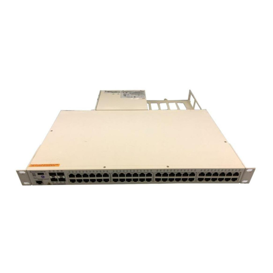
10/100/1000 Base-T Power over Ethernet (PoE), as well as four combo individually configurable to 10/ 100/1000 Base-T PoE or 1000 Base-X high speed connections. The front panel of the OS6850-P48 chassis contains the following major components: • System status and slot indicator LEDs •... - Page 62 CLASS 1 LASER PRODUCT Console Console Port Combo SFP The OS6850-P48 front panel The OS6850-P48 provides four combo SFP connec- provides one RJ-45 port for con- tors for 1000Base-X high-speed connections. sole connections. Console con- nections are used by network...
- Page 63 OmniSwitch 6850 Series Chassis and Hardware Components OS6850-P48 Specifications Total unshared 10/100/1000Base-T PoE per switch (5–48) Total shared 10/100/1000Base-T PoE combo per switch (1–4) Total combo 1000Base-X combo SFP connectors per switch (1–4) Total 10/100/1000Base-T PoE per stack Total combo SFP connectors per...
- Page 64 OmniSwitch 6850-P48 OS6850-P48 Specifications Cable supported (RJ-45) Power supplied to port Maximum cable distance (RJ-45) page 2-44 OmniSwitch 6850 Series Chassis and Hardware Components 10BaseT: unshielded twisted-pair (UTP) 100BaseTX: unshielded twisted-pair (UTP), Category 5, EIA/TIA 568 or shielded twisted-pair (STP), Category 5, 100 ohm 1000BaseT: unshielded twisted-pair (UTP), Category 5e 15.4 watts per port...
-
Page 65: Omniswitch 6850-P24X
OmniSwitch 6850 Series Chassis and Hardware Components OmniSwitch 6850-P24X The OmniSwitch 6850-P24X is a stackable edge/workgroup switch offering 20 unshared 10/100/1000 Base-T Power over Ethernet (PoE), two (2) 10 Gigabit XFP connectors, as well as four combo individu- ally configurable to 10/100/1000 Base-T PoE or 1000 Base-X high speed connections. The front panel of the OS6850-P24X chassis contains the following major components: •... - Page 66 OmniSwitch 6850-P24X Refer to the illustration below for more front panel information. For detailed LED descriptions, refer to page 2-53. For information on the chassis rear panel, refer to 10/100/1000Mbps PoE The OS6850-P24X provides 20 fixed 10/100/ USB Port 1000BaseT non-combo PoE (1–20) and 4 fixed High speed USB port, which can be 10/100/1000BaseT combo PoE (21–24).
- Page 67 OmniSwitch 6850 Series Chassis and Hardware Components OS6850-P24X Specifications Total unshared 10/100/1000Base-T PoE per switch (1–20) Total shared 10/100/1000Base-T PoE combo per switch (21–24) Total combo 1000Base-X combo SFP connectors per switch (21–24) Total XFP Connectors (25–26) Total 10/100/1000Base-T PoE per stack Total combo SFP connectors per stack...
- Page 68 OmniSwitch 6850-P24X OS6850-P24X Specifications Connections supported Cable supported (RJ-45) Power supplied to port Maximum cable distance (RJ-45) page 2-48 OmniSwitch 6850 Series Chassis and Hardware Components IP phones, Bluetooth Access Points, Internet cameras, and other devices requiring power over Ethernet 10BaseT: unshielded twisted-pair (UTP) 100BaseTX: unshielded twisted-pair (UTP), Category 5, EIA/TIA 568 or shielded twisted-pair (STP), Category 5, 100 ohm...
-
Page 69: Omniswitch 6850-P48X
OmniSwitch 6850 Series Chassis and Hardware Components OmniSwitch 6850-P48X The OmniSwitch 6850-P48X is a stackable edge/workgroup switch offering 48 unshared 10/100/ 1000Base-T Power over Ethernet (PoE) and two (2) 10 Gigabit XFP connectors. The front panel of the OS6850-P48X chassis contains the following major components: •... - Page 70 OmniSwitch 6850-P48X Refer to the illustration below for more front panel information. For detailed LED descriptions, refer to page 2-53. For information on the chassis rear panel, refer to Status and Slot Indicator LEDs For information on the OS6850-P48X’s status and slot indicator LEDs, refer to page 2-53.
- Page 71 OmniSwitch 6850 Series Chassis and Hardware Components OS6850-P48X Specifications Total unshared 10/100/1000Base-T PoE per switch (1–48) Total XFP Connectors (49–50) Total 10/100/1000Base-T PoE per stack Power Flash memory size RAM memory size Overall Width (rack-mount flanges included) Chassis Width (rack-mount flanges not included) Height Height (rack units)
- Page 72 OmniSwitch 6850-P48X OS6850-P48X Specifications Maximum cable distance (RJ-45) RJ-45 page 2-52 OmniSwitch 6850 Series Chassis and Hardware Components 100 meters OmniSwitch 6850/6850E Series Hardware Users Guide June 2011...
-
Page 73: Status Leds
OmniSwitch 6850 Series Chassis and Hardware Components Status LEDs LEDs provide visual status information. These “status lights” are used to indicate conditions, such as hardware and software status, primary role status, power supply status, primary and secondary status (stacked configurations), fan and temperature errors, 10 Gigabit uplink status (when applicable), slot number information, data speed, link integrity, and activity. -
Page 74: 10/100/1000 Leds
Status LEDs 10/100/1000 LEDs There is a single LED for each corresponding 10/100/1000 Mbps port. It displays solid green (1000 Mbps) for a valid link; displays blinking green when transmitting or receiving packets in a link up state for non- PoE. -
Page 75: Rear Panel
OmniSwitch 6850 Series Chassis and Hardware Components Rear Panel The rear panel of OmniSwitch 6850 Series switches contains the following major components: • Two DB-25 connectors for the primary power supply, which can be used for a single large (i.e. 510W) power supply or two small (i.e. 126W) power supplies •... -
Page 76: Mounting The Switch
Mounting the Switch Mounting the Switch Note. If you are relocating the switch, be sure to power it down and remove all network, stacking, and power cables before moving. Airflow Considerations Be sure that your switch is placed in a well-ventilated, static-free environment. Always allow adequate clearance at the front, rear, and sides of the switch. -
Page 77: Chassis Airflow
OmniSwitch 6850 Series Chassis and Hardware Components Chassis Airflow The fans pull air from the air intake vent located on the left-hand side of the chassis. The air is directed horizontally through the chassis and past the circuit board. Airflow is then exhausted through the fan vents at the right-hand side of the chassis. -
Page 78: Blank Cover Panels
Mounting the Switch Blank Cover Panels Blank cover panels are provided with your switch and are used to cover empty backup power supply bays and 10 Gigabit uplink bays (all OmniSwitch 6850 Series switches, except for OmniSwitch 6850-24, OmniSwitch 6850-P24, OmniSwitch 6850-48, and OmniSwitch 6850-P48). These cover panels play an important role in chassis airflow and temperature management. -
Page 79: Installation Options
OmniSwitch 6850 Series Chassis and Hardware Components Installation Options The OmniSwitch 6850 Series switches can be installed in two ways: • Tabletop installation • Rack-mount installation Installing the Switch on a Tabletop or Bench OmniSwitch 6850 Series switches can be installed freestanding as tabletop units. Place your switch on a stable, flat, and static-free surface. -
Page 80: Rack-Mounting The Switch
19-inch rack-mount installations. These flanges must be attached to the chas- sis before the switch can be rack mounted. Note. If you are installing the switch in a 23-inch-wide rack, Alcatel-Lucent offers optional 23-inch rack- mounting hardware. For more information, contact your Alcatel-Lucent representative. •... -
Page 81: Installing And Removing Combo Port Sfps
OmniSwitch 6850 Series Chassis and Hardware Components After the rack-mount flanges are secured to the chassis, mark the holes on the rack where the switch is to be installed. Lift and position the switch until the rack-mount flanges are flush with the rack post. Align the holes in the flanges with the rack holes that were marked in step 3. -
Page 82: Setting Up A Stacked Configuration
Setting Up a Stacked Configuration Setting Up a Stacked Configuration Rack Mounting Stacked Configurations To rack mount a stacked configuration, install all switches that are to be included in the stacked configura- tion as described on pages 2-60 chassis. Note. You cannot mix OS6800 and OS6850 switches in a stack. Note. - Page 83 OmniSwitch 6850 Series Chassis and Hardware Components Starting from the top of the stack, insert one end of the stacking cable into either stacking port A or stacking port B. The stacking port (A or B) depends on your preferred cabling pattern. Refer to “Managing OmniSwitch 6850/6850E Series Stacks”...
- Page 84 Setting Up a Stacked Configuration To provide added resiliency and redundancy, you must install the redundant stacking cable to connect the top switch in the stack to the bottom switch. Connect the redundant cable now. Refer to the diagram below for more information: Redundant Connection Between Top and Bottom Switches Once all stacking cable connectors are inserted, tighten the captive screws at the left- and right-hand sides of each connector as shown.
-
Page 85: Booting Omniswitch 6850 Series Switches
If any of the LED state differs from the states shown in the table above, refer to mation. Contact Alcatel-Lucent Customer Support if the LED state persists. For information on logging in and configuring your OmniSwitch 6850 Series switch, refer to the OmniSwitch 6850 Series Getting Started Guide and OmniSwitch 6800/6850/9000 Series Switch Manage- ment Guide. -
Page 86: Booting Stacked Configurations
If any of the LED state differs from the states shown in the table above, refer to mation. Contact Alcatel-Lucent Customer Support if the LED state persists. For information on logging in and configuring your OmniSwitch 6850 Series stack, refer to the OmniSwitch 6850 Series Getting Started Guide and OmniSwitch 6800/6850/9000 Series Switch Management Guide. -
Page 87: Power Cords
OmniSwitch 6850 Series Chassis and Hardware Components Power Cords Since the power cord is the switch’s only disconnect device, it should be plugged into an easily accessible outlet. In the event that your power cord is lost or damaged, refer to the specifications below. Specifications The power cord to be used with 115 Volt configuration is a minimum type SJT (SVT) 18/3, rated at 250 Volts AC, 10 Amps with a maximum length of 15 feet. -
Page 88: Console Port
Console Port Console Port The console port, located on the chassis front panel, provides a console connection to the switch and is required when logging into the switch for the first time. By default, this RJ-45 connector provides a DTE console connection. - Page 89 OmniSwitch 6850 Series Chassis and Hardware Components To change the stop bits value, enter boot serialstopbits, followed by the number of stop bits. Options include 1 (default) and 2. For example: Boot > boot serialstopbits 2 Verify your current changes by entering show at the boot prompt: Boot >...
-
Page 90: Console Port Pinouts
Console Port Console Port Pinouts 10/100 Ethernet Port – RJ-45 Pinout (non-PoE) Pin Number Description not used not used not used not used Gigabit Ethernet Port – RJ-45 Pinout Pin Number Description BI_DB+ BI_DB- BI_DA+ BI_DD+ BI_DD- BI_DA- BI_DC+ BI_DC- 10/100/1000 Mbps Power over Ethernet Port –... -
Page 91: Rj-45 Console Port - Connector Pinout
OmniSwitch 6850 Series Chassis and Hardware Components RJ-45 Console Port – Connector Pinout Pin Number Signals as DTE Console Port Ground Ground OmniSwitch 6850/6850E Series Hardware Users Guide June 2011 Console Port page 2-71... - Page 92 Console Port OmniSwitch 6850 Series Chassis and Hardware Components page 2-72 OmniSwitch 6850/6850E Series Hardware Users Guide June 2011...
-
Page 93: Omniswitch 6850E Series Chassis And Hardware Components
3 OmniSwitch 6850E Series Chassis and Hardware OmniSwitch 6850/6850E Series Switches • OmniSwitch 6850E-24 (see • OmniSwitch 6850E-P24 (see • OmniSwitch 6850E-24X (see • OmniSwitch 6850E-P24X (see • OmniSwitch 6850E-48 (see • OmniSwitch 6850E-P48 (see • OmniSwitch 6850E-48X (see • OmniSwitch 6850E-P48X (see •... -
Page 94: Chapter 3 Omniswitch 6850E Series Chassis And Hardware Components
OmniSwitch 6850E-24 O mni S witch 6850E-C24 R ear C onsole R ear Item Description LED Indicator Seven segment LED provides stack element ID. USB Port High speed USB port. System Status LEDs Provides status on hardware, software, primary and redundant power. 10/100/1000BaseT RJ-45 Ports and LEDs 10/100/1000BaseT non-combo and 10/100/1000BaseT combo ports. -
Page 95: Omniswitch 6850E-24 Rear Panel
OmniSwitch 6850E Series Chassis and Hardware Components OmniSwitch 6850E-24 Rear Panel Item Description Grounding Block Type LCD8-10A-L grounding lug Redundant Power Supply Connector DB-25 connector for optional external redundant power supply. Primary Power Supply Connector DB-25 connector for required external primary power supply. Stacking/SFP+ Uplink Module Connectors for use in stacking switches into a virtual chassis or as uplink ports. -
Page 96: Os6850E-24 Specifications
OS6850E-24 Specifications Total non-combo 10/100/ 1000Base-T ports Total 10/100/1000Base-T or SFP combo ports Maximum SFP+ ports Maximum CX4 stacking ports Power Flash memory size RAM memory size Width Height Height (rack units) Depth Weight Relative Humidity Ambient Temperature Altitude Maximum frame size Ethernet standards Maximum cable distance (RJ-45) 1. -
Page 97: Omniswitch 6850E-P24
OmniSwitch 6850E Series Chassis and Hardware Components OmniSwitch 6850E-P24 O mni S witch 6850E-P24 R ear C onsole R ear Item Description LED Indicator Seven segment LED provides stack element ID. USB Port High speed USB port. System Status LEDs Provides status on hardware, software, primary and redundant power. -
Page 98: Omniswitch 6850E-P24 Rear Panel
OmniSwitch 6850E-P24 Rear Panel Item Description Redundant Power Supply Connector DB-25 connector for optional external redundant power supply. Grounding Block Type LCD8-10A-L grounding lug Redundant Power Supply Connector DB-25 connector for optional redundant power supply. Primary Power Supply Connector DB-25 connector for required primary power supply. Stacking/SFP+ Uplink Module Connectors for use in stacking switches into a virtual chassis or as uplink ports. -
Page 99: Os6850E-P24 Specifications
OmniSwitch 6850E Series Chassis and Hardware Components OS6850E-P24 Specifications Total non-combo 10/100/ 1000Base-T PoE ports Total 10/100/1000Base-T PoE or SFP combo ports Total PoE ports (non-combo and combo) Maximum SFP+ ports Maximum CX4 stacking ports Power Flash memory size RAM memory size Width Height Height (rack units) -
Page 100: Omniswitch 6850E-24X
OmniSwitch 6850E-24X O mni S witch 6850E-C24X CLASS 1 LASER PRODUCT R ear C onsole R ear Item Description LED Indicator Seven segment LED provides stack element ID. USB Port High speed USB port. System Status LEDs Provides status on hardware, software, primary and redundant power. 10/100/1000BaseT RJ-45 Ports and LEDs 10/100/1000BaseT non-combo and 10/100/1000BaseT combo ports. -
Page 101: Omniswitch 6850E-24X Rear Panel
OmniSwitch 6850E Series Chassis and Hardware Components OmniSwitch 6850E-24X Rear Panel Item Description Grounding Block Type LCD8-10A-L grounding lug Redundant Power Supply Connector DB-25 connector for optional external redundant power supply. Primary Power Supply Connector DB-25 connector for required external primary power supply. Stacking/SFP+ Uplink Module Connectors for use in stacking switches into a virtual chassis or as uplink ports. -
Page 102: Os6850E-24X Specifications
OS6850E-24X Specifications Total non-combo 10/100/ 1000Base-T ports Total 10/100/1000Base-T or SFP combo ports Maximum SFP+ ports Maximum CX4 stacking ports Power Flash memory size RAM memory size Width Height Height (rack units) Depth Weight Relative Humidity Ambient Temperature Altitude Maximum frame size Ethernet standards Maximum cable distance (RJ-45) 1. -
Page 103: Omniswitch 6850E-P24X
OmniSwitch 6850E Series Chassis and Hardware Components OmniSwitch 6850E-P24X O mni S witch 6850E-P24X CLASS 1 LASER PRODUCT R ear C onsole R ear Item Description LED Indicator Seven segment LED provides stack element ID. USB Port High speed USB port. System Status LEDs Provides status on hardware, software, primary and redundant power. -
Page 104: Omniswitch 6850E-P24X Rear Panel
OmniSwitch 6850E-P24X Rear Panel Item Description Redundant Power Supply Connector DB-25 connector for optional external redundant power supply. Grounding Block Type LCD8-10A-L grounding lug Redundant Power Supply Connector DB-25 connector for optional external redundant power supply. Primary Power Supply Connector DB-25 connector for required external primary power supply. -
Page 105: Os6850E-P24X Specifications
OmniSwitch 6850E Series Chassis and Hardware Components OS6850E-P24X Specifications Total non-combo 10/100/ 1000Base-T PoE ports Total 10/100/1000Base-T PoE or SFP combo ports Total PoE ports (non-combo and combo) Maximum SFP+ ports Maximum CX4 stacking ports Power Flash memory size RAM memory size Width Height Height (rack units) -
Page 106: Omniswitch 6850E-48
OmniSwitch 6850E-48 O mni S witch 6850E-C48 R ear CLASS 1 LASER PRODUCT C onsole R ear Item Description LED Indicator Seven segment LED provides stack element ID. USB Port High speed USB port. System Status LEDs Provides status on hardware, software, primary and redundant power. 10/100/1000BaseT RJ-45 Ports and LEDs 10/100/1000BaseT non-combo and 10/100/1000BaseT combo ports. -
Page 107: Omniswitch 6850E-48 Rear Panel
OmniSwitch 6850E Series Chassis and Hardware Components OmniSwitch 6850E-48 Rear Panel Note. The figure shows a pre-production version of the chassis without product, safety, and compliance information labels. All production versions of the chassis have these labels. Item Description Grounding Block Type LCD8-10A-L grounding lug Redundant Power Supply Connector DB-25 connector for optional external redundant power supply. -
Page 108: Os6850E-48 Specifications
OS6850E-48 Specifications Total non-combo 10/100/ 1000Base-T PoE ports Total 10/100/1000Base-T or SFP combo ports per switch Maximum SFP+ ports Maximum CX4 stacking ports Power Flash memory size RAM memory size Width Height Height (rack units) Depth Weight Relative Humidity Ambient Temperature Altitude Maximum frame size Ethernet standards... -
Page 109: Omniswitch 6850E-P48
OmniSwitch 6850E Series Chassis and Hardware Components OmniSwitch 6850E-P48 O mni S witch 6850E-P48 R ear CLASS 1 LASER PRODUCT C onsole R ear Item Description LED Indicator Seven segment LED provides stack element ID. USB Port High speed USB port. System Status LEDs Provides status on hardware, software, primary and redundant power. -
Page 110: Omniswitch 6850E-P48 Rear Panel
OmniSwitch 6850E-P48 Rear Panel Item Description Redundant Power Supply Connector DB-25 connector for optional external redundant power supply. Grounding Block Type LCD8-10A-L grounding lug Redundant Power Supply Connector DB-25 connector for optional external redundant power supply. Primary Power Supply Connector DB-25 connector for required external primary power supply. -
Page 111: Os6850E-P48 Specifications
OmniSwitch 6850E Series Chassis and Hardware Components OS6850E-P48 Specifications Total non-combo 10/100/ 1000Base-T PoE ports Total 10/100/1000Base-T PoE or SFP combo ports per switch Total PoE ports (non-combo and combo) Maximum SFP+ ports Maximum CX4 stacking ports Power Flash memory size RAM memory size Width Height... -
Page 112: Omniswitch 6850E-48X
OmniSwitch 6850E-48X O mni S witch 6850E-48X CLASS 1 LASER PRODUCT R ear C onsole R ear Item Description LED Indicator Seven segment LED provides stack element ID. USB Port High speed USB port. System Status LEDs Provides status on hardware, software, primary and redundant power. 10/100/1000BaseT RJ-45 Ports and LEDs 10/100/1000BaseT non-combo and 10/100/1000BaseT combo ports. -
Page 113: Omniswitch 6850E-48X Rear Panel
OmniSwitch 6850E Series Chassis and Hardware Components OmniSwitch 6850E-48X Rear Panel Item Description Grounding Block Type LCD8-10A-L grounding lug Redundant Power Supply Connector DB-25 connector for optional external redundant power supply. Primary Power Supply Connector DB-25 connector for required external primary power supply. Stacking/SFP+ Uplink Module Connectors for use in stacking switches into a virtual chassis or as uplink ports OmniSwitch 6850/6850E Series Hardware Users Guide... -
Page 114: Os6850E-48X Specifications
OS6850E-48X Specifications Total non-combo 10/100/ 1000Base-T PoE ports Total 10/100/1000Base-T or SFP combo ports per switch Maximum SFP+ ports Maximum CX4 stacking ports Power Flash memory size RAM memory size Width Height Height (rack units) Depth Weight Relative Humidity Ambient Temperature Altitude Maximum frame size Ethernet standards... -
Page 115: Omniswitch 6850E-P48X
OmniSwitch 6850E Series Chassis and Hardware Components OmniSwitch 6850E-P48X O mni S witch 6850E-P48X CLASS 1 LASER PRODUCT R ear C onsole R ear Item Description LED Indicator Seven segment LED provides stack element ID. USB Port High speed USB port. System Status LEDs Provides status on hardware, software, primary and redundant power. -
Page 116: Omniswitch 6850E-P48X Rear Panel
OmniSwitch 6850E-P48X Rear Panel Item Description Redundant Power Supply Connector DB-25 connector for optional external redundant power supply. Grounding Block Type LCD8-10A-L grounding lug Redundant Power Supply Connector DB-25 connector for optional external redundant power supply. Primary Power Supply Connector DB-25 connector for required external primary power supply. -
Page 117: Os6850E-P48X Specifications
OmniSwitch 6850E Series Chassis and Hardware Components OS6850E-P48X Specifications Total non-combo 10/100/ 1000Base-T PoE ports Total 10/100/1000Base-T PoE or SFP combo ports per switch Total PoE ports (non-combo and combo) Maximum SFP+ ports Maximum CX4 stacking ports Power Flash memory size RAM memory size Width Height... -
Page 118: Omniswitch 6850E-U24X
OmniSwitch 6850E-U24X Item Description LED Indicator Seven segment LED provides stack element ID. USB Port High speed USB port. System Status LEDs Provides status on hardware, software, primary and redundant power. SFP Ports and LEDs Combo and non-combo SFP connectors for various supported SFP transceivers. Console Port RS-232 console port with an RJ-45 connector. -
Page 119: Omniswitch 6850E-U24X Rear Panel
OmniSwitch 6850E Series Chassis and Hardware Components OmniSwitch 6850E-U24X Rear Panel Item Description Grounding Block Type LCD8-10A-L grounding lug Redundant Power Supply Connector DB-25 connector for optional external redundant power supply. Primary Power Supply Connector DB-25 connector for required external primary power supply. Stacking/SFP+ Uplink Module Connectors for use in stacking switches into a virtual chassis or as uplink ports. -
Page 120: Os6850E-U24X Specifications
OS6850E-U24X Specifications Total non-combo SFP ports Maximum SFP+ ports Maximum CX4 stacking ports Power Flash memory size RAM memory size Width Height Height (rack units) Depth Weight Relative Humidity Ambient Temperature Altitude Maximum frame size Ethernet standards Maximum cable distance (RJ-45) 1. -
Page 121: Os6-Xni-U2 Module
OmniSwitch 6850E Series Chassis and Hardware Components OS6-XNI-U2 Module Item Description SFP+ Ports and LEDs Two SFP+ connectors for various supported SFP+ transceivers. Refer to “OmniSwitch 6850E LED Status Indicators” on page 3-31 Refer to “OmniSwitch 6850E Port Numbering” on page 3-30 To check the status of the uplink/stacking module use the show ni command. -
Page 122: Omniswitch 6850E Port Numbering
OmniSwitch 6850E Port Numbering The table below lists the port numbering for the OmniSwitch 6850E Series switches. Non-Combo Ports OS6850E-24 1-20 OS6850E-P24 1-20 OS6850E-24X 1-20 OS6850E-P24X 1-20 OS6850E-48 5-48 OS6850E-P48 5-48 OS6850E-48X 3-48 OS6850E-P48X 3-48 OS6850E-U24X 1-22 page 3-30 OmniSwitch 6850E Series Chassis and Hardware Components Combo Ports Non-Combo SFP+ Ports... -
Page 123: Omniswitch 6850E Led Status Indicators
OmniSwitch 6850E Series Chassis and Hardware Components OmniSwitch 6850E LED Status Indicators 10/100/1000 SFP/SFP+ Rear OmniSwitch 6850/6850E Series Hardware Users Guide OmniSwitch 6850E LED Status Indicators State Description Solid Green System software is operational. Solid Amber Hardware or System failure. Blinking Green Normal Diagnostics. -
Page 124: Console Port
Console Port Console Port The console port, located on the chassis front panel, provides a console connection to the switch and is required when logging into the switch for the first time. By default, this RJ-45 connector provides an RS- 232 DTE console connection. - Page 125 OmniSwitch 6850E Series Chassis and Hardware Components To change the stop bits value, enter boot serialstopbits, followed by the number of stop bits. Options include 1 (default) and 2. For example: Boot > boot serialstopbits 2 Verify your current changes by entering show at the boot prompt: Boot >...
-
Page 126: Port Pinouts
Console Port Port Pinouts 10/100 Ethernet Port – RJ-45 Pinout (non-PoE) Pin Number Description not used not used not used not used Gigabit Ethernet Port – RJ-45 Pinout Pin Number Description BI_DB+ BI_DB- BI_DA+ BI_DD+ BI_DD- BI_DA- BI_DC+ BI_DC- 10/100/1000 Mbps Power over Ethernet Port – RJ-45 Pinout Pin Number Description RX+ (-VDC) -
Page 127: Rj-45 Console Port - Connector Pinout
OmniSwitch 6850E Series Chassis and Hardware Components RJ-45 Console Port – Connector Pinout Pin Number Signals as DTE Console Port Ground Ground OmniSwitch 6850/6850E Series Hardware Users Guide June 2011 Console Port page 3-35... - Page 128 Console Port OmniSwitch 6850E Series Chassis and Hardware Components page 3-36 OmniSwitch 6850/6850E Series Hardware Users Guide June 2011...
-
Page 129: Chapter 4 Omniswitch 6850/6850E Series Power Supplies
4 OmniSwitch 6850/6850E Series Power Supplies OmniSwitch 6850/6850E Series switches various Power over Ethernet (PoE) and non-PoE AC and DC Power supplies. This chapter includes detailed information on these power supply types. Topics include: • Power suppy technical specifications • Power supply chassis support •... -
Page 130: Omniswitch 6850/6850E Series Power Supplies
OmniSwitch 6850/6850E Series Power Supplies OmniSwitch 6850/6850E Series Power Supplies OmniSwitch 6850/6850E Series switches support the following power supplies: • PS-900W-AC power supply (see • PS-510W-AC power supply (see • PS-510W-AC-E power supply (see • PS-360W-AC power supply (see • PS-360W-AC-E power supply (see •... -
Page 131: Power Supply Shelf
OmniSwitch 6850/6850E Series Power Supplies Power Supply Shelf Alcatel-Lucent requires the use of power supply shelf when the power supply is used in a 1U (i.e, 1.5 inches/3.8 cm) configuration. In a 2U (i.e., 3 inches/7.6 cm) configuration you can mount the power supply tray directly to a rack. -
Page 132: Ps-900Ac-P Power Supply
OmniSwitch 6850/6850E Series Power Supplies PS-900AC-P Power Supply The PS-900AC-P Power Supply provides system and PoE power and can be installed as either a primary or redundant power supply. P/S Component Model Provides Primary and Redundant System and PoE For Input Voltage Range Rated Frequency Maximum PoE Output Power... -
Page 133: Ps-510W-Ac Power Supply
OmniSwitch 6850/6850E Series Power Supplies PS-510W-AC Power Supply The PS-510W-AC Power Supply provides system and PoE power and can be installed as either a primary or redundant power supply. P/S Component Model Provides Primary and Redundant System and PoE For Input Voltage Range Rated Frequency Maximum PoE Output Power... -
Page 134: Ps-510W-Ac-E Power Supply
OmniSwitch 6850/6850E Series Power Supplies PS-510W-AC-E Power Supply The PS-510W-AC-E Power Supply provides enhanced system and PoE power and can be installed as either a primary or redundant power supply. 510W AC Enhanced System/PoE Power Supply P/S Component Model Provides Primary and Redundant System and PoE For Input Voltage Range Rated Frequency... -
Page 135: Ps-360W-Ac Power Supply
OmniSwitch 6850/6850E Series Power Supplies PS-360W-AC Power Supply The PS-360W-AC Power Supply provides system and PoE and can be installed as either a primary or redundant power supply. P/S Component Model Provides Primary and Redundant System and PoE For Input Voltage Range Rated Frequency Maximum PoE Output Power Maximum System Output Power 130 W... -
Page 136: Ps-360W-Ac-E Power Supply
OmniSwitch 6850/6850E Series Power Supplies PS-360W-AC-E Power Supply The PS-360W-AC-E Power Supply provides enhanced system and PoE and can be installed as either a primary or redundant power supply. 360W Enhanced AC System/PoE Power Supply P/S Component Model Provides Primary and Redundant System and PoE For Input Voltage Range Rated Frequency... -
Page 137: Ps-126W-Ac Power Supply
OmniSwitch 6850/6850E Series Power Supplies PS-126W-AC Power Supply The PS-126W-AC Power Supply provides system power and can be installed as a redundant system power supply. P/S Component Model Provides Primary and Redundant System and PoE For Input Voltage Range Rated Frequency Maximum Output Power Output Voltage Output Current... -
Page 138: Ps-120W-Dc Power Supply
OmniSwitch 6850/6850E Series Power Supplies PS-120W-DC Power Supply The PS-120W-DC Power Supply provides full system power and can be installed as a redundant system power supply. P/S Component Model Provides Primary and Redundant System and PoE For Input Voltage Range Input Current Maximum Output Power Output Voltage... -
Page 139: Installing Power Supplies
OmniSwitch 6850/6850E Series Power Supplies Installing Power Supplies Power supply can be installed in the following ways: • As a primary or backup supply directly connected to the back of a chassis. See Supply Directly to the Chassis” on page 4-11 •... -
Page 140: Connecting A Power Supply With A Cable
OmniSwitch 6850/6850E Series Power Supplies Carefully slide the power supply against the back of the chassis until the power connector connects. If you have installed the power shelf tighten the captive screws (or screws) located at back of the power supply to the power shelf. - Page 141 OmniSwitch 6850/6850E Series Power Supplies Carefully slide the power supply on to the power shelf and secure the power supply to the shelf using the captive screws. Attaching a Power Supply to the Power Shelf Note. A single large (i.e. 510W) power supply or up to two smaller (i.e. 126W) power supplies can be attached to a power supply shelf.
-
Page 142: Connecting The Power Supply Cable
OmniSwitch 6850/6850E Series Power Supplies Once the screws at the bottom of each flange are secure, install the remaining two rack mount screws. Be sure that all screws are securely tightened. Connecting the Power Supply Cable Follow the steps below to connect a power supply with a cable: Be sure the switch and power shelf are securely fastened to the rack. - Page 143 OmniSwitch 6850/6850E Series Power Supplies OmniSwitch 6850/6850E Series Power Supplies 1 3 . 5 i n c h e Redundant Small Power Supplies (i.e 126W) 1 3 . 5 i n c h e Redundant Large Power Supplies (i.e. 510W) OmniSwitch 6850/6850E Series Hardware Users Guide June 2011 page 4-15...
-
Page 144: Dc Power Supply Considerations
OmniSwitch 6850/6850E Series Power Supplies You can also attach the power supplies to the back of a chassis directly as well as using cables at the same time, as shown in the diagram below. DC Power Supply Considerations In addition to the installation steps described in page 4-11 “Connecting a Power Supply with a Cable”... -
Page 145: Connecting A Dc Power Source
OmniSwitch 6850/6850E Series Power Supplies Connecting a DC Power Source The DC power supply on your switch contains a power connector with three (3) square slots for connect- ing the positive, negative, and ground wires from a DC power source. Side Screws for Connector Removal OmniSwitch DC Power Supply Connector OmniSwitch 6850/6850E Series Hardware Users Guide... -
Page 146: Installing Dc Power Source Wire Leads
OmniSwitch 6850/6850E Series Power Supplies A clamp inside each slot keeps the power wire tightly in place during operation. The DC power supply has side screws that can be used to remove the connector if required. Installing DC Power Source Wire Leads These instructions describe how to connect your 3-wire DC power source to the power connector on your DC power supply. - Page 147 OmniSwitch 6850/6850E Series Power Supplies Tighten the clamp by tightening the screw above the slot into which you inserted the wire lead. The wire lead should be securely attached inside the connector. You should be able to pull on the wire and not dislodge it.
-
Page 148: Viewing The Power Supply Status
OmniSwitch 6850/6850E Series Power Supplies Viewing the Power Supply Status The switch constantly monitors the power supply operation. If either the primary or backup power source (optional) unexpectedly shuts down, the switch sends out a notification to the user. In addition, the power LED on the chassis front panel display solid amber. -
Page 149: Monitoring The Chassis
OmniSwitch 6850/6850E Series Power Supplies Monitoring the Chassis OmniSwitches can be monitored and managed via the console port using Command Line Interface (CLI) commands. The switches can also be monitored and managed via the Ethernet using CLI commands, WebView, SNMP, and OmniVista. The section below provides some examples of useful hardware-related monitoring CLI commands. -
Page 150: Checking The Fan Status
Monitoring the Chassis Checking the Fan Status To check the current status for all six fans in the chassis, use the -> show fan Chassis Fan Status -------+---+----------- Running Running Running Running Running Running For a complete list of output definitions for this command, refer to the OmniSwitch CLI Reference Guide. Checking the Power Supply Status For information on checking power supplies, refer to Additional Monitoring Commands... -
Page 151: Managing Power Over Ethernet (Poe)
As the switches fully support 10/100/1000 Ethernet connectivity, you may also attach non-PD equipment, such as computer workstations, printers, servers, etc. to the PoE ports. Important. Alcatel-Lucent recommends that PoE-enabled switches with attached IP telephones should have operational power supply redundancy at all times for 911 emergency requirements. In addition, both the switch and the power supply should be plugged into an Uninterruptible Power Source (UPS). -
Page 152: In This Chapter
Note. You can also monitor all chassis components and manage many chassis features, including Power over Ethernet, with WebView, Alcatel-Lucent’s embedded web-based device management application. WebView is an interactive and easy-to-use GUI that can be launched from the OmniVista or a web browser. -
Page 153: Power Over Ethernet Specifications
Managing Power over Ethernet (PoE) Power over Ethernet Specifications The table below lists general specifications for Alcatel-Lucent’s Power over Ethernet support. For more detailed power supply and Power Source Equipment (PSE) specifications, refer to “OmniSwitch 6850/6850E Series Power Supplies.” IEEE Standards supported... -
Page 154: Viewing Poe Power Supply Status
Viewing PoE Power Supply Status Viewing PoE Power Supply Status To view the current status of power supplies installed in the backup power supply, use the command, as shown below: -> show power Slot Wattage Type ----+----+---------+------+-----------+---------- The backup power supply will always display as “PS-2”. For detailed information on the show power command output, refer to the CLI Command Reference Guide. -
Page 155: Configuring Power Over Ethernet Parameters
Managing Power over Ethernet (PoE) Configuring Power over Ethernet Parameters Power over Ethernet Defaults The following table lists the defaults for PoE configuration: Parameter Description PoE operational status Total power available to a port Total power available to an entire slot Power priority level for a port Capacitor detection method Priority disconnect status... -
Page 156: Setting The Poe Operational Status
Configuring Power over Ethernet Parameters Setting the PoE Operational Status Enabling PoE By default, Power over Ethernet is administratively enabled in the switch’s system software. However, in order to physically activate PoE, you must issue the before any connected PDs will receive inline power. To activate power to PoE-capable in a switch, enter the corresponding slot number only. -
Page 157: Configuring The Total Power Available To A Slot
Managing Power over Ethernet (PoE) Configuring the Total Power Available to a slot Like the maximum port power allowance, the system software also provides a maximum slot-wide power allowance. By default, each slot is authorized by the system software to use a number of watts to power all devices connected to its ports depending on which power supply is used. -
Page 158: Setting The Capacitor Detection Method
Note. The capacitive detection method should only be enabled to support legacy IP phones. This feature is not compatible with IEEE specifications. Please contact your Alcatel-Lucent sales engineer or Customer Support representative to find out which Alcatel-Lucent IP phones models need capacitive detection enabled. -
Page 159: Understanding Priority Disconnect
Managing Power over Ethernet (PoE) Understanding Priority Disconnect The priority disconnect function differs from the port priority function described on applies only to the addition of powered devices (PDs) in tight power budget conditions. Priority discon- nect is used by the system software in determining whether an incoming PD will be granted or denied power when there are too few watts remaining in the PoE power budget for an additional device. -
Page 160: Priority Disconnect Is Enabled; Same Priority Level On All Pd
Understanding Priority Disconnect Priority Disconnect is Enabled; Same Priority Level on All PD Reminder. Priority disconnect examples are applicable only when there is inadequate power remaining to power an incoming device. When a PD is being connected to a port with the same priority level as all other in the slot, the physical port number is used to determine whether the incoming PD will be granted or denied power. -
Page 161: Priority Disconnect Is Disabled
Managing Power over Ethernet (PoE) Priority Disconnect is Disabled Reminder. Priority disconnect examples are applicable only when there is inadequate power remaining to power an incoming device. When priority disconnect is disabled, power will be denied to any incoming PD, regardless of its port priority status (i.e., low, high, and critical) or physical port number (i.e., 1–24). -
Page 162: Monitoring Power Over Ethernet Via Cli
Monitoring Power over Ethernet via CLI Monitoring Power over Ethernet via CLI To monitor current PoE statistics and settings, use the displays a list of all current PoE-capable, along with the following information for each port: • Maximum power available to the port, in milliwatts •... -
Page 163: Chapter 6 Managing Omniswitch 6850/6850E Series Stacks
6 Managing OmniSwitch 6850/6850E Series Stacks In addition to their working as individual stand-alone switches, an OmniSwitch can also be linked together to work as a single virtual chassis known as a stack. With stacks, users can easily expand their switching capacity simply by adding additional switches to the stack. -
Page 164: In This Chapter
Monitoring the stack on page Note. You can also manage and monitor stacks through WebView, Alcatel-Lucent’s embedded web-based device management application. WebView is an interactive and easy-to-use GUI that can be launched from OmniVista or a web browser. Please refer to WebView’s online documentation for more informa- tion. -
Page 165: Omniswitch 6850/6850E Series Stacking Specifications
Managing OmniSwitch 6850/6850E Series Stacks OmniSwitch 6850/6850E Series Stacking Specifications The following table lists OmniSwitch Stacking specifications. Models Supporting Stacking Maximum Switches in a Stack Default Chassis Mode of 6850E Default Daughter Module Mode of 6850E Note. After changing the chassis or module mode the switch must be rebooted. Changing OS6850E Chassis Mode OmniSwitch 6850E switches can be stacked with other OS6850E or OS6850 switches. - Page 166 OmniSwitch 6850/6850E Series Stacking Specifications The following example shows how to change the mode to stacking using the -> interfaces 1/25 mode stacking WED JUL 01 18:08:29 : HSM-CHASSIS (101) info message: +++ Ni 1 Port 25,26 are set to stackable for next boot:OK ->...
-
Page 167: Omniswitch 6850/6850E Series Stack Overview
Managing OmniSwitch 6850/6850E Series Stacks OmniSwitch 6850/6850E Series Stack Overview Users can configure up to eight switches, in any combination of chassis types, into a single virtual chassis known as a stack. With stacks, switching capacity can be easily expanded simply by adding additional switches to the stack. - Page 168 Roles Within the Stack Important Note. For management module redundancy to work effectively, the software on all switches operating in the stack must be synchronized at all times. Refer to page 6-39 for more information. Primary Secondary Idle Idle Offline Secondary Idle Idle...
- Page 169 Managing OmniSwitch 6850/6850E Series Stacks Primary Secondary Offline Secondary Offline Primary Secondary Primary Redundant Management Module Failover (Two Switches) OmniSwitch 6850/6850E Series Hardware Users Guide A stack of two switches is operating normally. The stack consists of a primary module and a secondary module.
-
Page 170: Primary Management Module Selection
Roles Within the Stack Primary Management Module Selection For a stack of switches to operate as a virtual chassis, there must be a mechanism for dynamically select- ing the switch within the stack that will assume the primary management role. OmniSwitch 6850/6850E Series switches use three different methods for selecting the primary switch. - Page 171 Managing OmniSwitch 6850/6850E Series Stacks Using Saved Slot Information The saved slot number is the slot number the switch will assume following a reboot. This information is stored in a switch’s boot.slot.cfg file; the switch reads its slot number assignment from this file at bootup and assumes the specified slot number within the stack.
- Page 172 Roles Within the Stack Using Switch Uptime A user can override both the MAC address and saved slot methods for determining a stack’s primary management module. This is done by controlling the uptime of switches in the stack. If all elements of a stack are powered off, the user can force a particular switch to become primary by powering on that switch and waiting a minimum of 15 seconds before powering on any other switches.
-
Page 173: Secondary Management Module Selection
Managing OmniSwitch 6850/6850E Series Stacks Secondary Management Module Selection In order to provide effective management module redundancy, all stacked configurations dynamically assign a backup, or secondary, management module during the boot process. Stacks use two different methods for selecting the secondary switch. These methods are: •... - Page 174 Roles Within the Stack Using Saved Slot Information If a stack with preassigned slot information for each switch is booted, the switch with the second lowest slot value is assigned the secondary management role. For example, if a stack of four switches is booted and the preassigned slot values for each switch are 1, 2, 3, and 4, the switch with the slot value of 2 is assigned the secondary role.
-
Page 175: Idle Module Role
Managing OmniSwitch 6850/6850E Series Stacks Idle Module Role Switches that are not assigned either the primary or secondary role in a stack are, by default, assigned the role of idle modules. These idle modules operate similarly to Network Interface (NI) modules in a chassis- based switch. -
Page 176: Pass-Through Mode
Roles Within the Stack Pass-Through Mode The pass-through mode is a state in which a switch has attempted to join a stack but has been denied primary, secondary, and idle status. When a switch is in the pass-through mode, its Ethernet are brought down (i.e, they cannot pass traffic). -
Page 177: Recovering From Pass-Through Mode (Duplicate Slot Numbers)
Managing OmniSwitch 6850/6850E Series Stacks To avoid a pass-through condition following a reboot, make sure that all saved slot values for the stack are unique. Use the stack set slot slot 3 from 2 to 3: -> stack set slot 3 saved-slot 2 Use the show stack topology command to verify the change:... - Page 178 Roles Within the Stack To resolve this pass-through condition, simply assign slot 1001 a new saved slot value and reboot the module. This can be done in either of two ways: • Use the stack set slot command to assign the new value, then use the to reboot the module: ->...
- Page 179 Managing OmniSwitch 6850/6850E Series Stacks In some pass-through conditions (for example, larger stacks where multiple switches are in pass-through mode), it might be desirable to correct any duplicate saved slot assignments and then reboot the entire stack. The recovery from pass-through can be accomplished with fewer steps than reassigning slot numbers and rebooting modules on a slot-by-slot basis.
-
Page 180: Stack Cabling
Stack Cabling Stack Cabling Switches in a stack are connected to each other by stacking cables. The stacking cables come in various sizes as listed below and provide high-speed, dual-redundant links between switches in a stack. Cable Description OS6850-CBL-30 30 centimeters long stacking cable. OS6850-CBL-60 60 centimeters long stacking cable. -
Page 181: Redundant Stacking Cable Connection
Managing OmniSwitch 6850/6850E Series Stacks Note. When planning the stack cabling configuration, keep in mind that the switch connected to stacking port A of the primary switch will be assigned the secondary management role by default. Examples of Stacking Cable Patterns (Chassis Rear Panels Shown) Redundant Stacking Cable Connection OmniSwitches allow redundant stacking cable connections between the top-most and bottom-most switches in a stack. - Page 182 Stack Cabling The figure below shows how the redundant connection between the top and bottom switches in the stack ensures that data will continue to flow throughout the stack, even in the event of a connection failure at one of the stacking cables. Stacking Cables Slot 1 Slot 2...
-
Page 183: Checking Redundant Stacking Cable Status
Managing OmniSwitch 6850/6850E Series Stacks Redundant stacking cables provide a form of dual redundancy. As shown in the figure above, the redun- dant cable allows traffic to flow in the event of a stacking link failure. The redundant cable also provides failover if a switch goes down within the stack. -
Page 184: Slot Numbering
Slot Numbering Slot Numbering For a stack of switches to operate as a virtual chassis, each module in the stack must be assigned a unique slot number. To view the current slot assignments for a stack, use the commands. The slot number is also displayed on the front panel of each switch by the LED located on the left side of the chassis (refer to There are two ways stacking modules are assigned slot numbers: •... -
Page 185: Dynamic Slot Number Assignment
Managing OmniSwitch 6850/6850E Series Stacks Dynamic Slot Number Assignment Dynamic slot number assignment occurs when there are no boot.slot.cfg files present in the switches’ /flash directories. This is the case for new, “out of the box,” switches that have not been previously booted. - Page 186 Slot Numbering If the switch with the lowest MAC address happens to be the bottom-most module in the stack, slot numbering will not resume from the top of the stack. Instead, the system software will select the second- ary module using the standard method (i.e., the switch connected to the primary’s stacking port A), then continue to number the stack from the bottom up.
-
Page 187: Manual Slot Number Assignment
Managing OmniSwitch 6850/6850E Series Stacks Manual Slot Number Assignment To manually assign slot numbers to one or more modules in a stack, use the command writes slot information to the boot.slot.cfg file located in a switch’s /flash directory. It is this saved slot information that the switch will assume following a reboot. -
Page 188: Reverting To The Dynamic Slot Numbering Model
Slot Numbering When the stack comes up following the reboot, the manually-configured slot numbers display as follows: Slot 1 - Primary Slot 2 - Secondary Slot 3 - Idle Slot 4 - Idle Slot 5 - Idle Slot 6 - Idle Slot 7 - Idle Slot 8 - Idle The stack set slot command can also be used to manually correct duplicate saved slot assignments within... -
Page 189: Hot-Swapping Modules In A Stack
Managing OmniSwitch 6850/6850E Series Stacks Hot-Swapping Modules In a Stack Modules within a virtual chassis are hot-swappable. NI modules are essentially those modules operating in the stack in idle mode. These modules can be removed from, or added to, an existing stack without disrupting other modules in the stack. -
Page 190: Merging Stacks
Hot-Swapping Modules In a Stack Merging Stacks Merging stacks involves connecting two or more operational stacks and attempting to reboot them as a single virtual chassis. In most cases, errors will result. To merge stacks without causing errors, select one stack that is to remain up and running and then add modules from the other stack(s) by following the steps below: Make sure all switches are running the same software version. -
Page 191: Reloading The Primary Management Module
Managing OmniSwitch 6850/6850E Series Stacks Reloading Switches Reloading is essentially a soft boot of a switch. Users can reload stacked modules operating in any role— i.e., primary, secondary, idle, and pass-through. Refer to the sections below for more information. Reloading the Primary Management Module If the switch with the primary management role is reloaded, the switch with the secondary role automati- cally takes over primary management functions. - Page 192 Reloading Switches If there are only two switches in the stack, the switch that was reloaded (the former primary) assumes the secondary role when it comes back up. Primary - Slot 1 Secondary - Slot 2 -> reload primary Booting... Primary - Slot 2 Secondary - Slot 1 Primary - Slot 2...
-
Page 193: Reloading The Secondary Management Module
Managing OmniSwitch 6850/6850E Series Stacks Reloading the Secondary Management Module If the switch with secondary management role is reloaded, the idle switch with the lowest slot number will automatically assume the secondary role. The reloaded switch (the former secondary) will assume an idle role when it comes back up. - Page 194 Reloading Switches If there are only two switches in the stack, the switch that was reloaded (the former secondary) resumes the secondary role when it comes back up. Primary - Slot 1 Secondary - Slot 2 -> reload secondary Primary - Slot 1 Booting...
-
Page 195: Reloading Switches With Idle Roles
Managing OmniSwitch 6850/6850E Series Stacks Reloading Switches with Idle Roles Similar to reloading Network Interface (NI) modules on chassis-based switches modules operating in idle status within a stack can be reloaded via the CLI. Note. Any traffic being passed on the module’s Ethernet will be interrupted during the reboot. Other modules within the stack will continue to operate without interruption. -
Page 196: Reloading All Switches In A Stack
Reloading Switches Reloading All Switches in a Stack Reloading all switches in the stack is essentially a full reboot of the virtual chassis. This can be useful in restoring a stack’s previously configured topology—i.e., the stack’s saved slot numbers and management roles. - Page 197 Managing OmniSwitch 6850/6850E Series Stacks No Switches In the Stack Have Saved Slot Information If a full reload is issued and no switches in the stack have unique slot numbers, slot numbers will be assigned beginning with the switch with the lowest MAC address. (This can occur if the boot.slot.cfg file has been deleted from each switch’s /flash directory—e.g., by issuing the modules in the stack.) The switch with the lowest MAC address is assigned slot number 1 and given the primary management...
-
Page 198: Avoiding Split Stacks
Reloading Switches Avoiding Split Stacks The term “splitting” a stack refers to the creation of isolated modules within the virtual chassis. A split stack can result from the following conditions: • Two or more non-adjacent switches are reloaded simultaneously • The stack is reloaded without a redundant stacking cable connection The sections below offer simple guidelines for avoiding splitting the stack during the reload process. -
Page 199: Changing The Secondary Module To Primary
Managing OmniSwitch 6850/6850E Series Stacks Changing the Secondary Module to Primary Stacks allow users to manually force the secondary switch to assume the primary management role. This is referred to as “takeover.” The behavior of a takeover is similar to that of reloading the primary manage- ment module (see page 6-29). - Page 200 Changing the Secondary Module to Primary If there are only two switches in the stack, the former primary switch resumes the secondary role when it comes back up following the takeover. Primary - Slot 1 Secondary - Slot 2 -> takeover Booting...
-
Page 201: Synchronizing Switches In A Stack
Managing OmniSwitch 6850/6850E Series Stacks Synchronizing Switches in a Stack Management module synchronization refers to the process of copying all files in the /flash/working and /flash/certified directories of the primary management module to the /flash/working and /flash/certified directories of all the other switches in the stack. The system and configuration software on the non- primary switches—i.e., the secondary management module and any modules operating in idle—is over- written. -
Page 202: Monitoring The Stack
Monitoring the Stack Monitoring the Stack As shown in the previous sections, monitoring the current status and operation of all elements in a stack can help users avoid unexpected stack conditions. The table below includes CLI commands that are useful in monitoring stack conditions. -
Page 203: Appendix A Regulatory Compliance And Safety Information
A Regulatory Compliance and Safety Information This appendix provides information on regulatory agency compliance and safety for OmniSwitch 6850/ 6850E switches. Declaration of Conformity: CE Mark This equipment is in compliance with the essential requirements and other provisions of Directive 2004/108/EC (EMC), 2006/95/EC (LVD), 91/263/EEC (Telecom Terminal Equipment, if applicable), 1999/5/EC (R&TTE, if applicable) as amended by Directive 93/68/EEC (CE Mark Directive). -
Page 204: China Rohs: Hazardous Substance Table
对销售之日的所售产品, 本表显示, 阿尔卡特朗讯公司供应链的电子信息产品可能包含这些物质。注意: 在所售产 品中可能会也可能不会含有所有所列的部件。 This table shows where these substances may be found in the supply chain of Alcatel-Lucent electronic information products, as of the date of sale of the enclosed product. Note that some of the component types listed above may or may not be a part of the enclosed product. - Page 205 Regulatory Compliance and Safety Information China RoHS: Hazardous Substance Table Products are packaged using one or more of the following packaging materials: Corrugated Cardboard Corrugated Fiberboard Low-Density Polyethylene OmniSwitch 6850/6850E Hardware Users Guide June 2011 page A-3...
-
Page 206: Standards Compliance
Standards Compliance Standards Compliance The product bears the CE mark. In addition it is in compliance with the following other safety and EMC standards: All hardware switching modules used in an OmniSwitch 6850/6850E switch comply with Class A standards. Modules with copper connectors meet Class A requirements using unshielded (UTP) cables. Safety Standards •... -
Page 207: Environmental Standards
Regulatory Compliance and Safety Information Environmental Standards • ETS 300 019 Storage Class 1.1 • ETS 300 019 Transportation Class 2.3 • ETS 300 019 Stationary Use Class 3.1 FCC Class A, Part 15 This equipment has been tested and found to comply with the limits for Class A digital device pursuant to Part 15 of the FCC Rules.These limits are designed to provide reasonable protection against harmful interference when the equipment is operated in a commercial environment.This equipment generates, uses, and can radiate radio frequency energy and, if not installed and used in accordance with the instructions in... -
Page 208: Cispr22 Class A Warning
Standards Compliance CISPR22 Class A warning This is a Class A product. In a domestic environment, this product may cause radio interference. Under such circumstances, the user may be requested to take appropriate countermeasures. VCCI This is a Class A product based on the standard of the Voluntary Control Council for Interference by Information Technology Equipment (VCCI). -
Page 209: Translated Safety Warnings
Regulatory Compliance and Safety Information Translated Safety Warnings Chassis Lifting Warning Two people are required when lifting the chassis. Due to its weight, lifting the chassis unassisted can cause personal injury. Also be sure to bend your knees and keep your back straight when assisting with the lifting of the chassis. -
Page 210: Installation Warning
Translated Safety Warnings Installation Warning Only personnel knowledgeable in basic electrical and mechanical procedures should install or maintain this equipment. Français: Toute installation ou remplacement de l'appareil doit être réalisée par du personnel qualifié et compétent. Deutsch: Dieses Gerät soll nur von Personal installiert oder gewartet werden, welches in elektrischen und mechanischen Grundlagen ausgebildet ist. -
Page 211: Power Disconnection Warning
Regulatory Compliance and Safety Information Power Disconnection Warning Your switch is equipped with multiple power supplies. To reduce the risk of electrical shock, be sure to disconnect all power connections before servicing or moving the unit. Français: Il se peut que cette unité soit équipée de plusieurs raccordements d'alimentation. Pour supprimer tout courant électrique de l'unité, tous les cordons d'alimentation doivent être débranchés. -
Page 212: Dc Power Supply Connection Warning
DC Power Supply Connection Warning DC Power Supply Connection Warning For EMC/EMI, each DC/DC power supply requires that the ground wire is connected from each DC/DC power supply to Common Earth Ground. Français: Pour EMC/EMI, pour chaque alimentation DC/DC, il est impératif que le fil de terre soit branché... -
Page 213: Wrist Strap Warning
Français: L'électricité statique (ESD) peut endommager les composants du commutateur. Pour cette raison Alcatel-Lucent joint à l'envoi du châssis un bracelet antistatique à brancher sur la prise mise à la terre située en bas à droite du commutateur. Vous devrez mettre ce bracelet avant toute intervention hardware. -
Page 214: Instrucciones De Seguridad En Español
Deseche las baterías usadas según las instrucciones del fabricante. Las instrucciones del fabricante son como sigue: Devuelva el módulo con la batería del litio a Alcatel-Lucent. La batería del litio será substituida en la fábrica de Alcatel-Lucent. -
Page 215: Advertencia Sobre Una Apropiada Conexión A Tierra
Para este propósito, Alcatel-Lucent proporciona una pulsera antiestática y un terminal que pone a tierra situados cerca de la parte superior derecha del chasis. Para que la pulsera antiestática sea eficaz en la eliminación de ESD, las fuentes de alimentación se deben instalar en el chasis y enchufar en las salidas de CA con descarga a... - Page 216 Instrucciones de seguridad en español Regulatory Compliance and Safety Information page A-14 OmniSwitch 6850/6850E Hardware Users Guide June 2011...
- Page 217 2-26 OS6850-48L front panel OS6850-48X front panel 2-34 OS6850-P24 front panel 2-37 OS6850-P24L front panel 2-10 OS6850-P24X front panel 2-45 OS6850-P48 front panel 2-41 OS6850-P48L front panel 2-14 OS6850-P48X front panel 2-49 OS6850-U24X front panel 2-18 rack-mounting 2-60 rear panel...
- Page 218 OS6850-48 see OmniSwitch 6850-48 OS6850-48L see OmniSwitch 6850-48L OS6850-48X see OmniSwitch 6850-48X OS6850-P24 see OmniSwitch 6850-P24 OS6850-P24L see OmniSwitch 6850-P24L OS6850-P48 see OmniSwitch 6850-P48 OS6850-P48L see OmniSwitch 6850-P48L OS6850-P48X see OmniSwitch 6850-P48X OS6850-U24X see OmniSwitch 6850-U24X pass-through modules 6-14 reloading...
- Page 219 Index booting 2-66 cabling 2-62, 6-18 idle modules 6-13 management roles merging 6-28 monitoring 6-40 pass-through modules 6-14 rack-mounting 2-62 reloading 6-29, 6-34 setup 2-62 status LEDs 2-53 takeover command 6-37 technical specifications console port 2-68, 2-71, 3-32, 3-35 OmniSwitch 6850-24 2-24, 3-4 OmniSwitch 6850-24L OmniSwitch 6850-24X...
-
Page 220: Index
Index Index-4 OmniSwitch 6850 Series Hardware Users Guide June 2011...
Need help?
Do you have a question about the OS6850-P48 and is the answer not in the manual?
Questions and answers