Alcatel OmniSwitch 7700 Hardware User's Manual
Hide thumbs
Also See for OmniSwitch 7700:
- Supplemental user manual (130 pages) ,
- Troubleshooting manual (614 pages) ,
- Getting started manual (68 pages)

Related Manuals for Alcatel OmniSwitch 7700


Summary of Contents for Alcatel OmniSwitch 7700
- Page 1 Part No. 060157-10, Rev. G April 2005 OmniSwitch 7700/7800 Hardware Users Guide www.alcatel.com...
- Page 2 The specifications described in this guide are subject to change without notice. Copyright © 2005 by Alcatel Internetworking, Inc. All rights reserved. This document may not be repro- duced in whole or in part without the express written permission of Alcatel Internetworking, Inc.
-
Page 3: Table Of Contents
How is the Information Organized? .................. xi Documentation Roadmap ....................xi Related Documentation ....................xiii User Manual CD ......................xiv Technical Support ......................xiv Chapter 1 The OmniSwitch 7700 and 7800 ................1-1 Application Example .......................1-2 Availability Features .......................1-3 Hardware Redundancy .....................1-3 Smart Continuous Switching ..................1-4 Software Rollback ....................1-4... - Page 4 Power over Ethernet Overview ..................3-4 Power over Ethernet Components ...................3-6 OS7-IP-SHELF PoE Power Shelf ................3-6 OS7-IPS-600A PoE Power Supply ................3-7 Power Shelf and PoE Port Guidelines ................3-8 Non-Redundant Power Supply Configurations ............3-8 Redundant Power Supply Configurations ..............3-9 OmniSwitch 7700/7800 Hardware Users Guide April 2005...
- Page 5 Serial Connection to the Console/Modem Port ..........4-5 Configuring X-ON/X-OFF Protocol ................4-7 Converting the Console Port to a Modem Port ..........4-8 CMM Redundancy ......................4-9 CMM Failover Sequence ..................4-9 Synchronizing the Primary and Secondary CMMs ..........4-10 OmniSwitch 7700/7800 Hardware Users Guide April 2005...
- Page 6 Hot Swapping NI Modules ....................5-23 Removing and Adding Modules ...................5-24 Using the Grounding Wrist Strap and Chassis Grounding Lug ......5-24 Module Types and Slot Positions ................5-25 Removing a Module ....................5-25 Adding a Module ....................5-27 OmniSwitch 7700/7800 Hardware Users Guide April 2005...
- Page 7 Leer “información importante de seguridad” ..........A-12 Advertencia de acceso restringido ..............A-12 Advertencia de pulsera antiestática ..............A-12 Clase de seguridad ..................A-12 Advertencia de fuentes de poder ..............A-12 Index ........................Index-1 OmniSwitch 7700/7800 Hardware Users Guide April 2005...
- Page 8 Contents viii OmniSwitch 7700/7800 Hardware Users Guide April 2005...
-
Page 9: About This Guide
• OmniSwitch 7800 • The OmniSwitch 7700 includes 10 slots for high performance 10/100 Ethernet and Gigabit Ethernet Network Interface (NI) modules. The OmniSwitch 7800 includes 18 slots for high performance 10/100 Ethernet and Gigabit Ethernet NI modules. Unsupported Platforms... -
Page 10: When Should I Read This Manual
CLI commands that pertain directly to hardware configuration, but it is not intended as a software users guide. There are several OmniSwitch 7700/7800 users guides that focus on switch software configuration. Consult those guides for detailed information and examples for configuring your switch software to operate in a live network environment. -
Page 11: How Is The Information Organized
It also includes steps for common procedures, such as removing and installing switch components. The OmniSwitch 7700/7800/8800 Switch Management Guide is the primary users guide for the basic soft- ware features on a single switch. This guide contains information on the switch directory structure, basic file and directory utilities, switch access security, SNMP, and web-based management. - Page 12 When you are ready to connect your switch to the network, you will need to learn how the OmniSwitch implements fundamental software features, such as 802.1Q, VLANs, Spanning Tree, and network routing protocols. The OmniSwitch 7700/7800/8800 Network Configuration Guide contains overview informa- tion, procedures, and examples on how standard networking technologies are configured in the OmniSwitch 7700/7800.
-
Page 13: Related Documentation
About This Guide Related Documentation Related Documentation The following are the titles and descriptions of all the OmniSwitch 7700/7800 user manuals: OmniSwitch 7700/7800 Getting Started Guide • Describes the hardware and software procedures for getting an OmniSwitch 7700/7800 up and running. -
Page 14: User Manual Cd
Additionally, with 24-hour-a-day access to Alcatel’s Service and Support web page, you’ll be able to view and update any case (open or closed) that you have reported to Alcatel’s technical support, open a new case or access helpful release notes, technical bulletins, and manuals. For more infor- mation on Alcatel’s Service Programs, see our web page at eservice.ind.alcatel.com, call us at 1-800-995-... -
Page 15: The Omniswitch 7700 And 7800
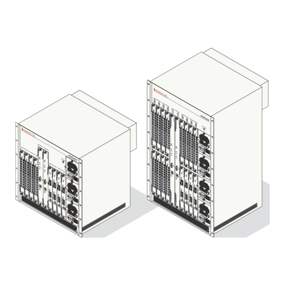
1 The OmniSwitch 7700 and 7800 OmniSwitch 7700/7800 switches offer high performance 10/100 Ethernet and Gigabit Ethernet capabili- ties, as well as embedded server load balancing for enterprise requirements. These switches come in two chassis configurations—the 10-slot OmniSwitch 7700 (OS7700) and the 18-slot OmniSwitch 7800 (OS7800). -
Page 16: Application Example
The OmniSwitch 7700 and 7800 Application Example The following application example shows one of the many ways OmniSwitch 7700 and 7800 switches can be used in an Enterprise network setting. Core Switch. In this example, an OS7800 is used as the core switch. Because the example network has •... -
Page 17: Availability Features
Power Checking Sequence • Information on software-related availability is provided in the OmniSwitch 7700/7800/8800 Switch Management Guide and the OmniSwitch 7700/7800/8800 Network Configuration Guide. Refer to the corresponding feature chapter (e.g., VRRP). Hardware Redundancy Hardware redundancy refers to backup hardware components. If primary hardware components fail or go offline for any reason, the redundant hardware automatically assumes the primary hardware functions (this is also referred to as failover). -
Page 18: Smart Continuous Switching
Availability Features The OmniSwitch 7700 and 7800 Smart Continuous Switching In redundant CMM configurations, the switch provides support for NIs during failover. In other words, if the primary CMM fails or goes offline for any reason, NI modules will continue data transmission and routing functions during the secondary CMM’s takeover process. -
Page 19: Hot Swapping
The OmniSwitch 7700 and 7800 Availability Features Hot Swapping Hot swapping refers to the action of adding, removing, or replacing certain hardware components without powering off your switch and disrupting other components in the chassis. This feature greatly facilitates hardware upgrades and maintenance and also allows you to easily replace components in the unlikely event of hardware failure. -
Page 20: Power Checking Sequence
Availability Features The OmniSwitch 7700 and 7800 Power Checking Sequence The power checking sequence is another built-in Availability feature. This feature helps regulate power in the switch whenever the switch is booted or an NI module is installed in the chassis. -
Page 21: Chapter 2 Chassis And Power Supplies
2 Chassis and Power Supplies OmniSwitch 7700 and 7800 switches come in two chassis configurations—the 10-slot OmniSwitch 7700 (OS7700) and the 18-slot OmniSwitch 7800 (OS7800). This chapter includes detailed information on each of these chassis types. Topics include: Chassis layout for OS7700 (10-slot) and OS7800 (18-slot) switches •... -
Page 22: Omniswitch 7800
100/115/250V 50/60Hz, 8.0/7.0/3.5 A LINK LINK LINK LINK AC OK DC OK OVER TEMP 100/115/250V 50/60Hz, 8.0/7.0/3.5 A Grounding Lug Network Interface (NI) Modules Air Intake Vent OmniSwitch 7800 Front View page 2-2 OmniSwitch 7700/7800 Hardware Users Guide April 2005... - Page 23 Front Rack Mount Flange Airflow Exhaust Vents (for power supplies) Fan Tray (contains three fans) for chassis temperature control and airflow exhaust Connectors for inline power supply. OmniSwitch 7800 Back View OmniSwitch 7700/7800 Hardware Users Guide April 2005 page 2-3...
- Page 24 Chassis Width (rack-mount flanges not included) 17 9/16 inches Height 29 3/4 inches Height (rack units) 17 RU Overall Depth (including required fan tray) 17 5/16 inches Chassis Depth (fan tray not included) 14 3/4 inches page 2-4 OmniSwitch 7700/7800 Hardware Users Guide April 2005...
-
Page 25: Omniswitch 7700
OmniSwitch 7700 OmniSwitch 7700 The OmniSwitch 7700 is a high performance switch offering eight slots for Ethernet and/or Gigabit Ether- net Network Interface (NI) modules. An additional two slots are reserved for primary and redundant Chassis Management Modules (CMMs). The OmniSwitch 7700 supports a maximum of three power supplies. - Page 26 Airflow Exhaust Vents control and airflow exhaust (for power supplies) Front Rack Mount Front Rack Mount Flange Flange Connectors reserved for use with inline power supply. OmniSwitch 7700 Back View page 2-6 OmniSwitch 7700/7800 Hardware Users Guide April 2005...
- Page 27 Chassis Width (rack-mount flanges not included) 17 9/16 inches Height 19 1/4 inches Height (rack units) 11 RU Overall Depth (including required fan tray) 17 5/16 inches Chassis Depth (fan tray not included) 14 3/4 inches OmniSwitch 7700/7800 Hardware Users Guide April 2005 page 2-7...
-
Page 28: Chassis Slot Numbering
CLI prompt: -> show module To view more detailed slot information, use the show module long form of this command. For example: -> show module long page 2-8 OmniSwitch 7700/7800 Hardware Users Guide April 2005... -
Page 29: Mounting The Switch
Note. Never obstruct the air intake vents located at the bottom-front and bottom-sides of the chassis or the fan unit’s air output vents located at the rear of the chassis. Clearance is not required at the top and bottom of the chassis. OmniSwitch 7700/7800 Hardware Users Guide April 2005 page 2-9... - Page 30 Mounting the Switch Chassis and Power Supplies Rack-Mounting Refer to the important guidelines below before installing the OmniSwitch 7700/7800 chassis in a rack. Be sure that all modules and power supplies are removed before rack-mounting the switch. For instruc- •...
- Page 31 For information on this optional rack mounting hardware, contact your Alcatel representative. Standalone The OmniSwitch 7700/7800 can be installed unmounted as a standalone unit. Be sure that the installation location is a stable, flat surface that can accommodate the fully-populated weight of all switches being installed.
-
Page 32: Power Supplies
Power Supplies Chassis and Power Supplies Power Supplies The OmniSwitch 7800 supports a total of four power supplies; the OmniSwitch 7700 supports a total of three power supplies (refer to page 2-23 for important redundancy information). The power supplies are installed in the power supply bays located at the right side of the chassis. - Page 33 Chassis and Power Supplies Power Supplies OmniSwitch 7700/7800 Power Supply Technical Specifications Input Voltage 100/115/220/230V Frequency 50/60Hz Input Power (per supply) 8/7/3.5/3.5 Amps maximum Input Power (per chassis) 8/7/3.5/3.5 Amps maximum (OS7700); 12/11/9/9 Amps maximum (OS7800) OmniSwitch 7700/7800 Hardware Users Guide...
-
Page 34: 600 Watt Dc-To-Dc Power Supply
A safety ground is provided on each power supply and is used to ground the OS7700/ OS7800 chassis. For information on properly connecting the ground, refer page 2-25. DC Power Supply Front Panel page 2-14 OmniSwitch 7700/7800 Hardware Users Guide April 2005... -
Page 35: Dc Power Supply Connection
Chassis and Power Supplies Power Supplies OmniSwitch 7700/7800 DC Power Supply Technical Specifications Input Voltage -48VDC to -60VDC Ambient Temperature 0–70 degrees Celsius (operating) -40–85 degrees Celsius (non-operating) Humidity 5% to 90% Relative Humidity (Operating) 0% to 95% Relative Humidity (Storage) -
Page 36: Chassis Power Supply Module Support
Four Power Supplies Provides complete power supply redundancy (if up to two power supplies are removed or go down unexpectedly). Refer to page 2-23 for more information on power supply redundancy. page 2-16 OmniSwitch 7700/7800 Hardware Users Guide April 2005... -
Page 37: Monitoring Chassis Power
Additional power errors may also occur, which can interrupt data flow on the switch. Therefore, it is important to manually check the current chassis power before adding a module. For examples, showing effective ways to check the current chassis power, refer to the examples beginning page 2-18. OmniSwitch 7700/7800 Hardware Users Guide April 2005 page 2-17... -
Page 38: Example 1: Adequate Power To Add A Module
As shown in the display, there are 288 watts of unused power in the chassis power supply budget. In this scenario, there was adequate power to add all NI modules, as well as the OS7800-CMM. page 2-18 OmniSwitch 7700/7800 Hardware Users Guide April 2005... -
Page 39: Example 2: Inadequate Power To Add A Module
8 watts. The module will not be power on until: One or more modules are removed from the chassis and the switch is rebooted • An additional power supply is added (if applicable) and the switch is rebooted • OmniSwitch 7700/7800 Hardware Users Guide April 2005 page 2-19... - Page 40 Power Control Checksum: 0x808, MAC Address: 00:d0:95:6b:0b:30, ASIC - Physical: 0x1901 0x0201 0x0201 0x001e 0x001e 0x001e Note that the module’s power requirement is 44 watts, as shown in the “Power Consumption” field. page 2-20 OmniSwitch 7700/7800 Hardware Users Guide April 2005...
-
Page 41: Checking Chassis Power Before Shutting Off Or Removing A Power Supply
Important Power Supply Redundancy Recommendation. It is strongly recommended that the switch maintains power supply redundancy whenever possible. Refer to “Power Supply Redundancy” on page 2-23 for detailed information on power supply redundancy. OmniSwitch 7700/7800 Hardware Users Guide April 2005 page 2-21... -
Page 42: Example 2: Inadequate Power To Remove A Power Supply
Additional Information. For instructions on installing and removing power supplies, refer to pages 2-24 through 2-26. For information on power supply redundancy, refer to “Power Supply Redundancy” on page 2-23. page 2-22 OmniSwitch 7700/7800 Hardware Users Guide April 2005... -
Page 43: Power Supply Redundancy
2-14 provides general power supply guidelines only. To verify that your switch has redundant power, you must follow the steps outlined beginning on page 2-17. OS7800 Power Supply Redundancy Example OmniSwitch 7700/7800 Hardware Users Guide April 2005 page 2-23... -
Page 44: Installing A Power Supply
Continue sliding the power supply back until the front panel meets the front of the chassis. Do not force the power supply into the bay. Otherwise you can damage the connectors. page 2-24 OmniSwitch 7700/7800 Hardware Users Guide April 2005... - Page 45 Once the power cord is looped through the retainer, plug the power cord connector into the power supply’s socket and then plug the power cord into an easily-accessible, properly grounded outlet. Do not use an extension cord. OmniSwitch 7700/7800 Hardware Users Guide April 2005 page 2-25...
-
Page 46: Removing A Power Supply
Be sure not to overtighten the captive screws. If you use a screwdriver, the torque used to tighten the screws must not exceed 2.3 inch pounds. page 2-26 OmniSwitch 7700/7800 Hardware Users Guide April 2005... -
Page 47: Power Cords
European cords must be Harmonized (HAR) type. Important. The specified replacement power cord for OmniSwitch 7700/7800 switches is 14-gauge (14/3). Do not use standard 18-gauge (18/3) cords such as those supplied with personal computers. -
Page 48: Redundant Ac Circuit Recommendation
DC OK OVER TEMP 100/115/250V 50/60Hz, 8.0/7.0/3.5 A LINK LINK LINK LINK LINK LINK AC Circuit 2 AC OK DC OK OVER TEMP 100/115/250V 50/60Hz, 8.0/7.0/3.5 A OS7700 Redundant AC Circuit Example page 2-28 OmniSwitch 7700/7800 Hardware Users Guide April 2005... -
Page 49: Grounding The Chassis
Temperature Range = UNDER THRESHOLD, Temperature Danger Threshold (deg C) = 80 For more information about these displays, see the “Chassis Management and Monitoring Commands” chapter in the OmniSwitch CLI Reference Guide. OmniSwitch 7700/7800 Hardware Users Guide April 2005 page 2-29... -
Page 50: Temperature Errors
See page page 2-32 for more information. • Note. When the danger threshold has been exceeded, the CMM’s TEMP LED will not reset from amber to green until after a system boot. page 2-30 OmniSwitch 7700/7800 Hardware Users Guide April 2005... -
Page 51: Chassis Fan Tray
Fan Tray Technical Specifications Power (OS7700) 107 watts (maximum) Power (OS7800) 107 watts (maximum) Important. The fan tray is a required component. Never attempt to operate the switch without the fan tray installed. OmniSwitch 7700/7800 Hardware Users Guide April 2005 page 2-31... -
Page 52: Monitoring Fan Tray Status
For detailed instructions on properly removing and installing a fan tray, refer to pages 2-33 through 2-34. Note. Fan trays are interchangeable between OS7700 and OS7800 chassis. page 2-32 OmniSwitch 7700/7800 Hardware Users Guide April 2005... -
Page 53: Removing The Fan Tray
Refer to the diagrams below for more information. Detach the fan tray by pulling it straight out and away from the chassis. Detaching the Fan Tray from the Chassis OmniSwitch 7700/7800 Hardware Users Guide April 2005 page 2-33... -
Page 54: Installing The New Fan Tray
When the attachment flanges are flush against the chassis’ rear panel, tighten the captive screws. Tighten the Captive Screws. When the attachment flanges are flush against the chassis’ rear panel, tighten the captive screws. Tightening the Captive Screws page 2-34 OmniSwitch 7700/7800 Hardware Users Guide April 2005... -
Page 55: Chassis Airflow
Fan Tray 1. Air Intake. The fan tray pulls air from the three air intake vents located at the bottom of the chassis. Air Intake Vents Airflow for OS7800 Switches OmniSwitch 7700/7800 Hardware Users Guide April 2005 page 2-35... - Page 56 1. Air Intake. The fan tray pulls air from the three air intake vents located at the bottom of the chassis. Air Intake Vents Airflow for OS7700 Switches page 2-36 OmniSwitch 7700/7800 Hardware Users Guide April 2005...
-
Page 57: Power Supply Fans
For OS7700 switches only, airflow for the top power supply is exhausted through the chassis fan tray. Airflow for Power Supplies page 2-12 for detailed power supply front panel and LED information. OmniSwitch 7700/7800 Hardware Users Guide April 2005 page 2-37... -
Page 58: Blank Cover Panels And Chassis Airflow
Air leakage due to missing cover panels Air Intake Vents Effects of Missing Blank Panels on Chassis Airflow page 2-38 OmniSwitch 7700/7800 Hardware Users Guide April 2005... -
Page 59: Managing Mac Addresses On The Switch
Managing MAC Addresses on the Switch Managing MAC Addresses on the Switch Your OmniSwitch 7700/7800 is shipped with thirty-two (32) factory-installed MAC addresses. These MAC addresses, which are stored on an EEPROM card in the chassis, are used by the switch as unique... -
Page 60: Os7700/Os7800 Mac Range Specifications
MAC address. For more infor- mation on VLAN router ports and MAC address allocation, refer to page 2-41. MAC router modes supported Multiple and single Default MAC router mode Multiple page 2-40 OmniSwitch 7700/7800 Hardware Users Guide April 2005... -
Page 61: Vlan Router Ports And Mac Address Allocation
MAC router mode. Multiple MAC router mode provides important compatibility with Alcatel’s Omni Switch/Router (OmniS/R) products. If you have OmniS/R products in your network and are using VLAN router ports on your switch, multiple MAC router mode should remain enabled. -
Page 62: Viewing Current Multiple Mac Router Mode Status
This mac alloc syntax is not a user command. Therefore, do not attempt to enter this syntax at the CLI prompt. It is system-generated syntax used to ensure that each new router port being assigned receives a unique MAC address. For more information about editing the boot.cfg file, see the OmniSwitch 7700/ 7800/8800 Switch Management Guide. - Page 63 EMP MAC address. The EMP MAC address is the last address in the range (in this example, • 00:d0:95:6b:09:5f).Although this address is also labeled CHASSIS, it can be differentiated from the base chassis MAC address because it is given an index value of 1. OmniSwitch 7700/7800 Hardware Users Guide April 2005 page 2-43...
- Page 64 Managing MAC Addresses on the Switch Chassis and Power Supplies page 2-44 OmniSwitch 7700/7800 Hardware Users Guide April 2005...
-
Page 65: Chapter 3 Installing And Managing Power Over Ethernet (Poe)
3 Installing and Managing Power over Ethernet (PoE) Power over Ethernet (PoE) is supported on OmniSwitch 7700 and 7800 switches and provides inline power directly from the switch’s Ethernet ports. Powered Devices (PDs) such as IP phones, wireless LAN stations, Ethernet hubs, and other access points can be plugged directly into the Ethernet ports. From these RJ-45 ports—provided on Alcatel’s OS7-ENI-P24 modules—the devices receive both electrical power... -
Page 66: In This Chapter
Note. You can also monitor all chassis components and manage many chassis features, including Power over Ethernet, with WebView, Alcatel’s embedded web-based device management application. WebView is an interactive and easy-to-use GUI that can be launched from OmniVista or a web browser. Please refer to WebView’s online documentation for more information. -
Page 67: Power Over Ethernet Specifications
Installing and Managing Power over Ethernet (PoE) Power over Ethernet Specifications Power over Ethernet Specifications The table below lists general specifications for Alcatel’s Power over Ethernet support. For more detailed power supply and Power Source Equipment (PSE) specifications, refer to “OS7-IP-SHELF Chassis Speci- fications”... -
Page 68: Power Over Ethernet Overview
Power Source (UPS)—to attached powered devices (PDs) located in a separate area of the building or campus. PDs include IP telephones and wireless LAN devices. Important. Alcatel recommends that PoE-enabled switches with attached IP telephones should have oper- ational power supply redundancy at all times for 911 emergency requirements. In addition, both the chas- sis and the power shelf should be plugged into an Uninterruptible Power Source (UPS). - Page 69 Note. Because OS7-ENI-P24 modules fully support 10/100 Ethernet connectivity, you may also attach non-PD equipment—such as computer workstations, printers, servers, etc.—to the OS7-ENI-P24 ports. Chapter 5, “Network Interface (NI) Modules,” for more information on the OS7-ENI-P24. OmniSwitch 7700/7800 Hardware Users Guide April 2005 page 3-5...
-
Page 70: Power Over Ethernet Components
-40 to +85 deg C, non-operating Humidity 5% to 90% Relative Humidity (Operating) 0% to 95% Relative Humidity (Storage) Altitude 10000 feet at +32 deg C, operat- ing; 50000 feet, non-operating page 3-6 OmniSwitch 7700/7800 Hardware Users Guide April 2005... -
Page 71: Os7-Ips-600A Poe Power Supply
OS7-IPS-600A PoE Power Supply Front Panel OS7-IPS-600A Power Supply Technical Specifications Power 600 watts Input Voltage 85–270 VAC Frequency 47–63 Hz Input Power 800 watts, maximum OmniSwitch 7700/7800 Hardware Users Guide April 2005 page 3-7... -
Page 72: Power Shelf And Poe Port Guidelines
For example, a PoE configuration with 192 powered devices, each requiring 6 watts of power, uses a total of 1152 watts. Because two power supplies support up to 1043 watts only, a total of three power supplies is required for this non-redundant 1152 watt PoE application. page 3-8 OmniSwitch 7700/7800 Hardware Users Guide April 2005... -
Page 73: Redundant Power Supply Configurations
Important. Alcatel recommends that PoE-enabled switches with attached IP telephones should have oper- ational power supply redundancy at all times for 911 emergency requirements. In addition, both the chas- sis and the power shelf should be plugged into an Uninterruptible Power Source (UPS). -
Page 74: Setting Up Power Over Ethernet Hardware
OS7700 or OS7800 chassis to provide a connection. For rack-mounted installations, the power shelf may be installed either above or below the switch • chassis. page 3-10 OmniSwitch 7700/7800 Hardware Users Guide April 2005... -
Page 75: Rack-Mounting The Power Shelf
19-inch rack mount installations. These flanges must be attached to the power shelf before the power shelf can be rack mounted. Note. If you are installing the power shelf in a 23-inch wide rack, Alcatel offers optional 23-inch rack- mounting hardware. For more information, contact your Alcatel representative. - Page 76 Note. Be sure to install the screws in the bottom hole of each flange, as shown, before proceeding. Once the screws at the bottom of each flange are secure, install the remaining two rack mount screws. Be sure that all screws are securely tightened. page 3-12 OmniSwitch 7700/7800 Hardware Users Guide April 2005...
-
Page 77: Installing The Power Supplies
Continue sliding the power supply back until the front panel meets the front of the chassis. Do not force the power supply into the bay. Otherwise you can damage the connectors. OmniSwitch 7700/7800 Hardware Users Guide April 2005 page 3-13... - Page 78 AC outlet or power source; do not use an extension cord or power strip. Note. For information on removing power supplies, refer to “Removing the Power Supplies” on page 3-15. page 3-14 OmniSwitch 7700/7800 Hardware Users Guide April 2005...
-
Page 79: Removing The Power Supplies
Be sure that the captive screw is completely disengaged from the threaded hole in the chassis before continuing. Note. Alcatel provides factory-installed blank cover plates for empty module slots. Do not remove these cover plates as they play an important role in chassis ventilation. - Page 80 Set the power supply aside on a clean, static-free surface. Remove all remaining power supplies by repeating steps 1 through 5. Note. For information on removing power supplies, refer to “Installing the Power Supplies” on page 3-13. page 3-16 OmniSwitch 7700/7800 Hardware Users Guide April 2005...
-
Page 81: Connecting The Power Shelf To The Chassis
Rear of Switch Chassis (Female) DB-25 PoE Connectors (Male) DB-25 PoE Connectors Rear of Power Shelf Chassis OmniSwitch 7700/7800 Hardware Users Guide April 2005 page 3-17... -
Page 82: Power Shelf Slot Numbering
OVER TEMP TEMP TEMP TEMP Power Shelf Slot Numbering Note. For information on slot numbering as displayed via the switch’s system software, refer to “Viewing Power Shelf Status” on page 3-19 page 3-18 OmniSwitch 7700/7800 Hardware Users Guide April 2005... -
Page 83: Viewing Power Shelf Status
Installed in left-hand bay of PoE Model Name: power shelf. Description: Part Number: Hardware Revision: Serial Number: Manufacture Date: Firmware Version: Admin Status: POWER ON, Operational Status: Power Provision: (Output continued on next page) OmniSwitch 7700/7800 Hardware Users Guide April 2005 page 3-19... - Page 84 Module in slot PS-7(Power Shelf slot 4) Installed in right-hand bay of Model Name: PoE power shelf. Description: Part Number: Hardware Revision: Serial Number: Manufacture Date: Firmware Version: Admin Status: POWER ON, Operational Status: Power Provision: page 3-20 OmniSwitch 7700/7800 Hardware Users Guide April 2005...
-
Page 85: Configuring Power Over Ethernet Parameters
If power to a particular port has been disconnected via the lanpower stop command, you can reactivate power to the port by specifying both the slot and port in the command line. For example: lanpower start 3/11 OmniSwitch 7700/7800 Hardware Users Guide April 2005 page 3-21... -
Page 86: Configuring The Total Power Allocated To A Port
Increasing the total power allocated to a slot may provide more demanding Powered Devices (PDs) with additional power required for operation. Decreasing the total power allocated to a slot helps preserve inline power and assists in the overall management of the switch’s power budget. page 3-22 OmniSwitch 7700/7800 Hardware Users Guide April 2005... -
Page 87: Setting Port Priority Levels
Enter the keyword enable in the command line, as shown: -> lanpower redundant-power enable To disable the feature, use the keyword disable in the command line: -> lanpower redundant-power disable OmniSwitch 7700/7800 Hardware Users Guide April 2005 page 3-23... -
Page 88: Setting The Capacitor Detection Method
Note. The capacitive detection method should only be enabled to support legacy IP phones only—this feature is not compatible with IEEE specification 802.3af. Please contact your Alcatel sales engineer or Customer Support representative to find out which Alcatel IP phones models need capacitive detection enabled. -
Page 89: Understanding Priority Disconnect
Be sure to specify the slot number in the command line. For example, the syntax lanpower 9 priority-disconnect enable enables priority disconnect on the OS7-ENI-P24 module installed in slot 9. OmniSwitch 7700/7800 Hardware Users Guide April 2005 page 3-25... -
Page 90: Priority Disconnect Is Enabled; Same Priority Level On All Pd Ports
Port 18 Current power budget has 2 watts available Power Shelf for incoming PDs Existing Powered Devices (PDs) Priority Disconnect Example 1: Feature is Enabled; Same Priority Level on All PD Ports page 3-26 OmniSwitch 7700/7800 Hardware Users Guide April 2005... -
Page 91: Priority Disconnect Is Enabled; Incoming Pd Port Has Highest Priority Level
Incoming Powered Device (PD) requiring Current power budget approx. 3.5 watts has 2 watts available for incoming PDs Priority Disconnect Example 2: Feature is Enabled; Incoming PD Port has Highest Priority Level OmniSwitch 7700/7800 Hardware Users Guide April 2005 page 3-27... -
Page 92: Priority Disconnect Is Enabled; Incoming Pd Port Has Lowest Priority Level
Current power budget has 2 watts available Power Shelf for incoming PDs Critical Existing Powered Devices (PDs) Priority Disconnect Example 3: Feature is Enabled; Incoming PD Port has Lowest Priority Level page 3-28 OmniSwitch 7700/7800 Hardware Users Guide April 2005... -
Page 93: Priority Disconnect Is Disabled
3.5 watts Port 1 Critical Port 24 Power Shelf Current power budget has 2 watts available for incoming PDs Existing Powered Devices (PDs) Priority Disconnect Example 4: Feature is Disabled OmniSwitch 7700/7800 Hardware Users Guide April 2005 page 3-29... -
Page 94: Monitoring Power Over Ethernet Via The Cli
Powered Off 15400 3000 Powered Off 15400 3000 Powered Off 15400 3000 Powered Off 15400 3000 Powered Off 15400 3000 Powered Off 15400 3000 Powered Off (Output continued on next page) page 3-30 OmniSwitch 7700/7800 Hardware Users Guide April 2005... - Page 95 364 Watts Total Power Budget Remaining 514 Watts Total Power Budget Available 1 Power Shelf Power Supplies Available Note. For detailed information on show lanpower command output, refer to the OmniSwitch CLI Refer- ence Guide. OmniSwitch 7700/7800 Hardware Users Guide April 2005 page 3-31...
-
Page 96: Power Over Ethernet Tutorial
Also, this new wireless LAN device will undergo critical testing within the network. Unexpected downtime should be avoided at all costs. Therefore, the priority value for the corresponding port must be increased to critical: -> lanpower 3/12 priority critical page 3-32 OmniSwitch 7700/7800 Hardware Users Guide April 2005... - Page 97 PoE power is conserved. A high-use PoE slot (e.g., slot 3) will have an increased power budget from which to draw necessary power for incoming PDs. OmniSwitch 7700/7800 Hardware Users Guide April 2005...
- Page 98 Power over Ethernet Tutorial Installing and Managing Power over Ethernet (PoE) page 3-34 OmniSwitch 7700/7800 Hardware Users Guide April 2005...
-
Page 99: Chapter 4 Chassis Management Module (Cmm)
4 Chassis Management Module (CMM) The Chassis Management Module (CMM) is the management unit for OmniSwitch 7700/7800 switches. In its role as the management unit, the CMM provides key system services, including: Console, modem, and Ethernet management port connections to the switch •... -
Page 100: Cmm Slot Locations
OS7700-CMMs and OS7800-CMMs use identical processor boards. However, OS7800-CMMs use twice the number of network interface-related ASICs on the fabric board. This is because OmniSwitch 7800 switches support up to 16 network interface (NI) modules and OmniSwitch 7700 switches support up to 8 NI modules. -
Page 101: Cmm Front Panel
CMM. For more informa- ACT. Flashes green as data is transmitted or tion on redundant CMM configurations, received on the CMM’s Ethernet management refer to page 4-9. port. CMM Front Panel (OS7700-CMM version shown) OmniSwitch 7700/7800 Hardware Users Guide April 2005 page 4-3... -
Page 102: Ethernet Management Port (Emp)
Default IP Address. The default IP address for the EMP is 192.168.10.1; the default gateway address is 192.168.1.254. For information on changing the EMP’s default IP address information, refer to the OmniSwitch 7700/7800 Getting Started Guide. page 4-4 OmniSwitch 7700/7800 Hardware Users Guide... -
Page 103: Access To The Emp
Note. You must be connected to the switch via the console port before attempting to change serial connec- tion settings. Otherwise, an error message will display. Enter modify boot parameters at the CLI prompt. The boot prompt displays: Boot > OmniSwitch 7700/7800 Hardware Users Guide April 2005 page 4-5... - Page 104 You can save your changes to the boot.params file by entering commit file at the boot prompt: Boot > commit file Note. When the commit file command is used, changes will not be enabled until after the next switch reboot. page 4-6 OmniSwitch 7700/7800 Hardware Users Guide April 2005...
-
Page 105: Configuring X-On/X-Off Protocol
For example, to disable X-ON/X-OFF on a console port enter: -> session xon-xoff disable Note. To enable or disable the X-ON/X-OFF protocol on the secondary CMM you must log into the secondary CMM and then execute the session xon-xoff command. OmniSwitch 7700/7800 Hardware Users Guide April 2005 page 4-7... -
Page 106: Converting The Console Port To A Modem Port
Note. Be sure to remove only the jumpers from the J100, J101, and J102 jumper blocks. page 4-8 OmniSwitch 7700/7800 Hardware Users Guide April 2005... -
Page 107: Cmm Redundancy
Ethernet Management Ports (EMPs) and Redundancy In redundant CMM configurations, the Ethernet Management Port (EMP) is only operational on the primary CMM. For additional information on the EMP, refer to page 4-4. OmniSwitch 7700/7800 Hardware Users Guide April 2005 page 4-9... -
Page 108: Synchronizing The Primary And Secondary Cmms
To synchronize the primary and secondary CMM modules, enter the following command at the CLI prompt: -> copy flash-synchro For more information on CMM synchronization and managing the /flash/working and /flash/certified directories, refer to the “Managing CMM Directory Content” chapter in the Switch Management Guide. page 4-10 OmniSwitch 7700/7800 Hardware Users Guide April 2005... -
Page 109: Hot Swapping Cmm Modules
CMM modules are synchronized. Otherwise, data flow and switch management functions may be interrupted due to incorrect or outdated software when the secondary CMM takes over. For more information, refer to “Synchronizing the Primary and Secondary CMMs” on page 4-10. OmniSwitch 7700/7800 Hardware Users Guide April 2005 page 4-11... - Page 110 For more information, refer to “Synchronizing the Primary and Secondary CMMs” on page 4-10. Note. For detailed instructions on physically installing and removing modules (both NIs and CMMs), refer Chapter 5, “Network Interface (NI) Modules.” page 4-12 OmniSwitch 7700/7800 Hardware Users Guide April 2005...
-
Page 111: Managing Cmm Modules
CMM you are currently logged in to is primary or secondary. For example: Current running CMM : PRIMARY, Current running configuration : WORKING Certify/Restore Status : CERTIFIED, Synchronization Status : SYNCHRONIZED OmniSwitch 7700/7800 Hardware Users Guide April 2005 page 4-13... - Page 112 Otherwise, data flow and switch management functions may be interrupted due to incorrect or outdated software when the secondary CMM takes over. For more information, refer to “Synchronizing the Primary and Secondary CMMs” on page 4-10. page 4-14 OmniSwitch 7700/7800 Hardware Users Guide April 2005...
-
Page 113: Monitoring Cmm Modules
Additional information, such as power control checksum, ASIC information, and chassis MAC • Address (see page 4-17 for information on MAC address storage) For a detailed information on the show cmm command, including output table descriptions, refer to the CLI Reference Guide. OmniSwitch 7700/7800 Hardware Users Guide April 2005 page 4-15... -
Page 114: Operating Status Of Cmm-Related Components
Chassis Management and Monitoring Commands show system show cmm show module long show hardware info show ni show module status show chassis show module page 4-16 OmniSwitch 7700/7800 Hardware Users Guide April 2005... -
Page 115: Chassis-Based Mac Address
Guide. MAC EEPROM Redundancy. A second EEPROM is provided for redundancy. An EEPROM card can be removed and replaced in the field by an authorized Alcatel Support Engineer in the unlikely event of an EEPROM failure. OmniSwitch 7700/7800 Hardware Users Guide... -
Page 116: Pinouts
Not used DTR (from CMM) Ground Ground Not used DSR (to CMM) Not used RTS (from CMM) Not used CTS (to CMM) Not used Not used Shell Chassis ground Chassis ground page 4-18 OmniSwitch 7700/7800 Hardware Users Guide April 2005... -
Page 117: Network Interface (Ni) Modules
Several Ethernet Network Interface (ENI), and Gigabit Network Interface (GNI) modules are currently available for OmniSwitch 7700/7800 switches. These modules come in a variety of port speeds, including auto-sensing 10/100 Mbps Ethernet, Fast Ethernet (100 Mbps), and Gigabit Ethernet (1 Gbps). In addi-... -
Page 118: Eni Modules
• LED-based monitoring. Refer to pages 5-3, 5-5, and 5-10 for LED descriptions. • NI support during CMM failover. Refer to “Smart Continuous Switching” on page 5-21 for details. • page 5-2 OmniSwitch 7700/7800 Hardware Users Guide April 2005... -
Page 119: Os7-Eni-C24/Os7-Eni2-C24 Front Panel
10BaseT locations. or 100BaseTX. The ports use RJ-45 connectors. Refer to the Technical Specifications table on page 5-4 for more information. LED Location Ethernet Port OS7-ENI-C24 Front Panel OmniSwitch 7700/7800 Hardware Users Guide April 2005 page 5-3... - Page 120 100BaseTX: unshielded twisted-pair (UTP), Category 5, EIA/TIA 568 or shielded twisted-pair (STP), Category 5, 100 ohm Maximum cable distance 100 meters Current draw 1.8 amps at 24 volts Power 44 watts (approximate) page 5-4 OmniSwitch 7700/7800 Hardware Users Guide April 2005...
-
Page 121: Os7-Eni-Fm12 Front Panel
MT-RJ connectors. Refer to the Technical Specifications table on page 5-6 for more information. Note page 5-30 for information on proper handling of MT-RJ connectors and fiber-optic cable. OS7-ENI-FM12 Front Panel OmniSwitch 7700/7800 Hardware Users Guide April 2005 page 5-5... - Page 122 Input optical power -8 dBm (minimum) Optical receiver sensitivity -31 dBm max. (multimode) ≈ Cable distances Multimode fiber 2 km Current draw 1.5 amps at 24 volts Power 37 watts (approximate) page 5-6 OmniSwitch 7700/7800 Hardware Users Guide April 2005...
-
Page 123: Os7-Eni-P24 Front Panel
IP telephones and LAN devices. Chapter 3, “Installing and Managing Power over Ethernet (PoE),” for detailed information. Refer to the Technical Specifications table on page 5-8 for more information. OS7-ENI-P24 Front Panel OmniSwitch 7700/7800 Hardware Users Guide April 2005 page 5-7... - Page 124 1.83 amps at 24 volts Power consumption 44 watts (approximate) Note. See Chapter 3, “Installing and Managing Power over Ethernet (PoE),” for information on configuring Power over Ethernet on the OS7-ENI-P24. page 5-8 OmniSwitch 7700/7800 Hardware Users Guide April 2005...
-
Page 125: Gni Modules
Like ENI modules, GNI modules are also supported during CMM failover. Refer to “Smart Continuous Switching” on page 5-21 for details. “Handling Fiber and Fiber Optic Connectors” on page 5-30 for proper handling of SC connectors and fiber-optic cable. OmniSwitch 7700/7800 Hardware Users Guide April 2005 page 5-9... -
Page 126: Os7-Gni-U2 Front Panel
• GBIC-C—1000BaseT Copper connection, supports distances up to 100 meters; uses one RJ-45 connector. Note page 5-30 for information on proper handling of SC connectors and fiber-optic cable. OS7-GNI-U2 Front Panel page 5-10 OmniSwitch 7700/7800 Hardware Users Guide April 2005... - Page 127 Note. Connector and cable information in the above table is dependent on the type of GBIC(s) installed in the OS7-GNI-U2 module. For a technical breakdown of each GBIC type, refer to “GBIC Specifications” on page 5-12. OmniSwitch 7700/7800 Hardware Users Guide April 2005 page 5-11...
-
Page 128: Gbic Specifications
70 km GBIC-C Technical Specifications Connector types RJ-45 Standards supported 802.3z, 1000Base-T Connections supported 1000Base-T connection to backbone or server Cable supported Copper ≈ Cable distances Multimode fiber 100 m, Category 5e page 5-12 OmniSwitch 7700/7800 Hardware Users Guide April 2005... -
Page 129: Installing Gbic Connectors
Caution. Do not force the GBIC into the slot. If the GBIC does not slide easily into position, verify that the GBIC grooves are aligned properly. Forcing the GBIC into the slot can damage the unit, as well as components on your GNI module. OmniSwitch 7700/7800 Hardware Users Guide April 2005 page 5-13... -
Page 130: Os7-Gni-U12/Os7-Gni2-U12 Front Panel
MINIGBIC-LX—1000BaseLX Single mode fiber, supports distances up to 10 km; uses LC connectors. • MINIGBIC-LH-70— 1000BaseLH Long haul fiber, supports distances up to 70 km; uses LC connectors. OS7-GNI-U12 Front Panel page 5-14 OmniSwitch 7700/7800 Hardware Users Guide April 2005... - Page 131 Note. Connector and cable information in the above table is dependent on the type of MiniGBIC(s) installed in the OS7-GNI-U12 module. For a technical breakdown of each MiniGBIC type, refer to “Mini- GBIC Specifications” on page 5-16. OmniSwitch 7700/7800 Hardware Users Guide April 2005 page 5-15...
-
Page 132: Minigbic Specifications
Fiber optic cable supported Single mode Wavelength 1550 nm (typical) Output optical power 0 to +5 dBm Input optical power -23 to -3 dBm ≈ Cable distances Long reach single mode fiber 70 km page 5-16 OmniSwitch 7700/7800 Hardware Users Guide April 2005... -
Page 133: Installing Minigbic Connectors
Note. To remove a MiniGBIC, you must first open the MiniGBIC’s hinged face to approximately ninety degrees. Then, grasp the hinged face and carefully pull the MiniGBIC straight out of the slot. OmniSwitch 7700/7800 Hardware Users Guide April 2005 page 5-17... -
Page 134: Removing Minigbic Connectors
Then, grasp the hinged face and carefully pull the MiniGBIC straight out of the slot. Slide the MiniGBIC out of the OS7-GNI-U12’s port. Store the MiniGBIC in a secure, static-free location. Placing the MiniGBIC in an anti-static bag is recommended. page 5-18 OmniSwitch 7700/7800 Hardware Users Guide April 2005... -
Page 135: Os7-Gni-C12/Os7-Gni2-C12 Front Panel
Ethernet cable connection exists. Refer to the Technical Specifications Flashes green as data is transmitted or table on page 5-20 for more informa- received on the port. tion. OS7-GNI-C12 Front Panel OmniSwitch 7700/7800 Hardware Users Guide April 2005 page 5-19... - Page 136 (STP), Category 5, 100 ohm Gigabit Cable supported 1000BaseT: unshielded twisted-pair (UTP), Category 5e Maximum cable distance 100 meters, Category 5 Current draw 2.21 amps at 24 volts Power 53 watts (approximate) page 5-20 OmniSwitch 7700/7800 Hardware Users Guide April 2005...
-
Page 137: Smart Continuous Switching
-> reload ni 3 For detailed information on the no power ni, power ni, and reload ni commands, refer to the “Chassis Management and Monitoring Commands” chapter in the OmniSwitch CLI Reference Guide. OmniSwitch 7700/7800 Hardware Users Guide April 2005 page 5-21... -
Page 138: Monitoring Ni Modules
0x1901 0x0201 0x0201 0x001e 0x001e 0x001e For more information about this display and other NI monitoring commands, see the “Chassis Management and Monitoring Commands” chapter in the OmniSwitch CLI Reference Guide. page 5-22 OmniSwitch 7700/7800 Hardware Users Guide April 2005... -
Page 139: Hot Swapping Ni Modules
Note. Although presence signalling is designed to maintain data flow on the switch during the hot swap procedure, uninterrupted data flow cannot be guaranteed. As a result, you should not hot swap NI or CMM modules during critical network activity. OmniSwitch 7700/7800 Hardware Users Guide April 2005 page 5-23... -
Page 140: Removing And Adding Modules
Chassis Management Modules, you must always ground yourself properly before removing or adding a module. For this purpose, Alcatel provides a grounding wrist strap and a grounding lug located near the bottom-right of the chassis. To properly ground yourself, follow the steps below. -
Page 141: Module Types And Slot Positions
First, loosen the module’s two captive screws that secure the module to the chassis. If necessary, use a flat-blade screwdriver to loosen the screws. Be sure that both captive screws are completely disengaged from the threaded holes in the chassis before continuing. OmniSwitch 7700/7800 Hardware Users Guide April 2005 page 5-25... - Page 142 Holding the module in both hands, carefully slide it out of the chassis along the card guide. The module should slide out easily. Do not force the module from the slot. n i S tc h , 8.0 LI NK LI NK , 8.0 , 8.0 page 5-26 OmniSwitch 7700/7800 Hardware Users Guide April 2005...
-
Page 143: Adding A Module
Once the notches have grasped the rail, press both extractor levers inward simultaneously until the module is firmly seated. Chassis Attachment Rail Notch in Extractor Lever OmniSwitch 7700/7800 Hardware Users Guide April 2005 page 5-27... - Page 144 Once the module is firmly seated, secure the module to the chassis by tightening the two captive screws. Be sure not to overtighten the captive screws. If you use a screwdriver, the torque used to tighten the screws must not exceed 2.3 inch pounds. page 5-28 OmniSwitch 7700/7800 Hardware Users Guide April 2005...
-
Page 145: Pinouts
10/100 Mbps Power over Ethernet Port – RJ-45 Pinout (OS7-ENI-P24) Pin Number Description +VDC +VDC -VDC -VDC 1 Gigabit Ethernet Port – RJ-45 Pinout (OS7-GNI-U2 and OS7-GNI-C12) Pin Number Description BI_DB+ BI_DB- BI_DA+ BI_DD+ BI_DD- BI_DA- BI_DC+ BI_DC- OmniSwitch 7700/7800 Hardware Users Guide April 2005 page 5-29... -
Page 146: Handling Fiber And Fiber Optic Connectors
It can also damage the fiber, although fiber is much tougher than most would assume. Still, it is highly recommended to buy only jumper cables with 3mm Kevlar jacketing, which offer superior protection and longer life. page 5-30 OmniSwitch 7700/7800 Hardware Users Guide April 2005... - Page 147 Inline attenuators eliminate the need for additional jumper cables and thus reduce the number of connec- tion interfaces. This increases the integrity of the optical path resulting in a more accurate test. OmniSwitch 7700/7800 Hardware Users Guide April 2005 page 5-31...
- Page 148 Handling Fiber and Fiber Optic Connectors Network Interface (NI) Modules page 5-32 OmniSwitch 7700/7800 Hardware Users Guide April 2005...
-
Page 149: Appendix A Regulatory Compliance And Safety Information
73/23/EEC und des 89/336/EEC, wie von Directive 93/68/EEC geändert. Español: Este directivo equipo está en conformidad con los requisitos esenciales y otras provisiones 73/23/EEC y 89/336/EEC según la enmienda prevista por Directive 93/68/EEC. OmniSwitch 7700/7800 Hardware Users Guide April 2005 page A-1... -
Page 150: Standards Compliance
ETS 300 019 Stationary Use Class 3.1 • All hardware switching modules used in an OmniSwitch 7700/7800 comply with Class A and Class B standards for digital devices per the FCC Part 15, ICES-003, EN 55022, CISPR 22, AS/NZS 3548, and VCCI standards. -
Page 151: Fcc Class A, Part 15
CISPR22 Class A warning This is a Class A product. In a domestic environment, this product may cause radio interference. Under such circumstances, the user may be requested to take appropriate countermeasures. OmniSwitch 7700/7800 Hardware Users Guide April 2005 page A-3... -
Page 152: Vcci
This is a Class A Information Product. When used in a residential environment, it may cause radio frequency interference. Under such circumstances, the user may be requested to take appropriate counter- measure. page A-4 OmniSwitch 7700/7800 Hardware Users Guide April 2005... -
Page 153: Translated Safety Warnings
Kabel angeschlossen oder gelöst werden, sowie keinerlei Installationen, Wartungen oder Konfigurationen vorgenommen werden. Español: Para evitar peligro de descargas, no conecte o desconecte ningun cable, ni realice ninguna insta- lación, maintenimiento o reconfiguración de este producto durante una tormenta eléctrica. OmniSwitch 7700/7800 Hardware Users Guide April 2005 page A-5... -
Page 154: Installation Warning
Español: Debido a que la apertura del puerto puede emitir radiación invisible cuando no hay un cable de fibra conectado, procurar no mirar directamente a las aperturas para no exponerse a la radiación. page A-6 OmniSwitch 7700/7800 Hardware Users Guide April 2005... -
Page 155: Lithium Battery Warning
Español: Si substituye las pilas de litio en su chasis, siempre utilice el mismo modelo o el tipo equiva- lente de pila recomendada por el fabricante. Deshágase de las pilas usadas según las instrucciones del fabricante. Devuelva el módulo con la pila de litio a Alcatel. La pila de litio será substituida en la fábrica de Alcatel. -
Page 156: Power Disconnection Warning
• toma de alimentación adecuadamente cableada y con toma de tierra. Cualquier otro equipo a cual se conecte este producto también debe estar conectado a tomas de • alimentación adecuadamente cableadas. page A-8 OmniSwitch 7700/7800 Hardware Users Guide April 2005... -
Page 157: Read Important Safety Information Warning
Español: Este equipo se debe instalar en un sitio con acceso restrinjido. Un sitio con el acceso restrinjido es uno seguro y con acceso limitado al personal de servicio que tiene una clave especial u otros medios de seguridad. OmniSwitch 7700/7800 Hardware Users Guide April 2005 page A-9... -
Page 158: Wrist Strap Warning
Français: L'électricité statique (ESD) peut endommager les composants du commutateur. Pour cette raison Alcatel joint à l'envoi du châssis un bracelet antistatique à brancher sur la prise mise à la terre située en bas à droite du commutateur. Vous devrez mettre ce bracelet avant toute intervention hardware. -
Page 159: Instrucciones De Seguridad En Español
Deseche las baterías usadas según las instrucciones del fabricante. Las instrucciones del fabricante son como sigue: Devuelva el módulo con la batería del litio a Alcatel. La batería del litio será substituida en la fábrica de Alcatel. -
Page 160: Advertencia Sobre Una Apropiada Conexión A Tierra
Debido a que la descarga electrostática (ESD) puede dañar componentes del interruptor, usted debe conec- tarse a tierra correctamente antes de continuar con la instalación del equipo. Para este propósito, Alcatel proporciona una pulsera antiestática y un terminal que pone a tierra situados cerca de la parte superior derecha del chasis. - Page 161 5-12 console/modem port 4-3, 4-5 GBIC-LH70 5-12 Ethernet Management Port 4-3, 4-4 GBIC-LX 5-12 failover GBIC-SX 5-12 front panel installing 5-13 hot swapping 4-11 technical specifications 5-12 LEDs managing 4-13 monitoring 4-15 OmniSwitch 7700/7800 Hardware Users Guide April 2005 Index-1...
- Page 162 MiniGBICs 5-16 front panel installing 5-17, 5-18 LEDs MiniGBIC-LH70 5-16 ports MiniGBIC-LX 5-16 technical specifications MiniGBIC-SX 5-16 OS7-ENI-FM12 technical specifications 5-16 front panel multiple MAC router mode 2-41 LEDs ports technical specifications Index-2 OmniSwitch 7700/7800 Hardware Users Guide April 2005...
- Page 163 2-13, 2-15 power cords 2-27 temperature management 2-29 power ni command 5-21 danger threshold 2-30 Power on LAN errors 2-30 see PoE warning threshold 2-30 Power over Ethernet temp-threshold command 2-30 see PoE OmniSwitch 7700/7800 Hardware Users Guide April 2005 Index-3...
-
Page 164: Index
Index Index-4 OmniSwitch 7700/7800 Hardware Users Guide April 2005...
Need help?
Do you have a question about the OmniSwitch 7700 and is the answer not in the manual?
Questions and answers