Table of Contents
Advertisement
Advertisement
Table of Contents

Related Manuals for Fujitsu Siemens Computers D1215


Summary of Contents for Fujitsu Siemens Computers D1215
- Page 1 COMPONENT .com Additional Technical Manual System board D1215 / D1214...
- Page 2 Our Hotline: Mo-Fr: 8 a.m. - 6 p.m. Sat: 9 a.m. - 2 p.m. Tel.: ++49 (0) 180 3777 005 · your sales outlet The latest information on our products, tips, updates, etc., can be found on the Internet under: http://www.fujitsu-siemens.com/mainboard...
- Page 4 Questo manuale è stato stampato su carta da riciclaggio. Denna handbok är tryckt på recyclingpapper. Dit handboek werd op recycling-papier gedrukt. Herausgegeben von/Published by Fujitsu Siemens Computers GmbH A26361-D1215-Z181-1-7619 Bestell-Nr./Order No.: Printed in the Federal Republic of Germany AG 0102...
- Page 5 System Board D1215/D1214 Additional Technical Manual January 2002 edition...
- Page 6 All other trademarks referenced are trademarks or registered trademarks of their respective owners, whose protected rights are acknowledged. Copyright ã Fujitsu Siemens Computers GmbH 2002 All rights, including rights of translation, reproduction by printing, copying or similar methods, even of parts are reserved.
-
Page 7: Table Of Contents
Auxiliary (MPEG, TV) audio connector (internal)..............9 Fan 1 connector.........................9 Configuration ...........................10 Functions controlled by the configuration switch ..............10 Power ............................10 Power requirement......................10 Power loadability......................10 Documentation ..........................11 Installing drivers..........................11 Upgrading main memory........................11 Troubleshooting..........................12 Message BIOS update......................12 The screen stays blank......................12 A26361-D1215-Z181-1-7619... -
Page 9: Introduction
Hold components by the edge, do not touch any pins or connectors on them. Once you have installed the system board, you should remove the battery protection (i.e. the thin plastic plate between battery and contact spring). A26361-D1215-Z181-1-7619 English -... -
Page 10: Features
ü / ü LAN onboard / with Alert-on-LAN ü Thermal Management onboard ü System Monitoring onboard Fujitsu Siemens Keyboard Power Button Support ü ü / - - / ü Buzzer onboard / int. Speaker Support Internal Connectors DIMM Sockets (SDRAM) AGP Slot (1/2/4x, 32Bit, 66 MHz) PCI Slots (32Bit, 33 MHz, 5 V and 3.3 V) -
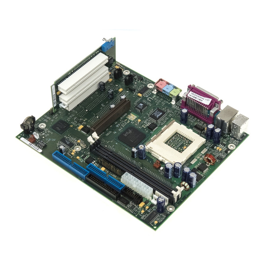
Page 11: Mechanics
4 = USB ports A and B Headphones 5 = Parallel port 9b = Audio Line-In 6 = Serial port 1 9c = Audio Micro-In The components and connectors marked are not necessarily present on the system board. English - 3 A26361-D1215-Z181-1-7619... - Page 12 14 = Cover monitoring supervised) * The components and connectors marked are not necessarily present on the system board. *) only for speed controllable fans (3 pin connector), for 2 pin processor fans use Fan2 connector only. 4 - English A26361-D1215-Z181-1-7619...
-
Page 13: Connectors
PS FAN control (low asserted) PS FAN full on (low asserted) PS FAN pulse SMB CLK SMB DATA VCC EEPROM Intrusion connector for case open detect for optional push-button (opener) Signal Case open (low asserted) Intrusion switch present (low asserted) English - 5 A26361-D1215-Z181-1-7619... -
Page 14: Serial Port 2 (Com 2)
1) Pin 8 is connected to VCC if audio is not onboard. Pin 8 is connected to GND if audio is onboard. 2) The sleep button (optional) functions only for operating systems with APM (not with ACPI). 6 - English A26361-D1215-Z181-1-7619... -
Page 15: Front Panel Connector
Pin 8 is connected to GND if audio is onboard. 2) The sleep button (optional) functions only for operating systems with APM (not with ACPI). Do not connect an internal speaker if a buzzer is onboard. English - 7 A26361-D1215-Z181-1-7619... -
Page 16: Fan 2 Connector
Shield GND VCC Dual / VCC (fused VCC Dual (fused max. max. 500mA and power 500mA and power supervision with over supervision with over current detection) current detection) Power supply on (CCR (max. 1 second low pulse) 8 - English A26361-D1215-Z181-1-7619... -
Page 17: Cd-Rom Audio Connector (Internal)
Right CD audio input Auxiliary (MPEG, TV) audio connector (internal) Signal Left AUX audio input Analog GND Analog GND Right AUX audio input Fan 1 connector Signal Controlled fan voltage (0 V / 6...12 V) Fan sense English - 9 A26361-D1215-Z181-1-7619... -
Page 18: Configuration
750 mA Keyboard port Not specified Mouse port Not specified Game port Not specified 500 mA Universal serial bus (USB) Port A 500 mA 500 mA Universal serial bus (USB) Port B 500 mA 10 - English A26361-D1215-Z181-1-7619... -
Page 19: Documentation
SDRAM modules with ECC can be plugged in but ECC is not functioning. Mix of ECC modules with non ECC modules is possible. Mix of PC100 and PC133 DIMMs is possible, but all modules will only work at PC100 speed. English - 11 A26361-D1215-Z181-1-7619... -
Page 20: Troubleshooting
If you have any problems with ACPI please ensure that all of your components are supporting ACPI S3 and S4. Operating system Hardware and drivers of controllers (e. g. audio, SCSI controllers). For further information please refer to http://developer.intel.com/technology/iapc/involve.htm. 12 - English A26361-D1215-Z181-1-7619...
Need help?
Do you have a question about the D1215 and is the answer not in the manual?
Questions and answers