Table of Contents
Advertisement
WARNING: For your safety the information in
this manual must be followed to minimize the
risk of fire or explosion or to prevent property
damage, personal injury or death.
— Do not store or use gasoline or other flammable
vapors and liquids in the vicinity of this or any
other appliance.
— WHAT TO DO IF YOU SMELL GAS:
• Do not try to light any appliance.
• Do not touch any electrical switch; do not
use any phone in your building.
• Clear the room, building or area of all
occupants.
• Immediately call your gas supplier from a
neighbor's phone. Follow the gas supplier's
instructions.
• If you cannot reach your gas supplier, call
the fire department.
— Installation and service must be performed by a
qualified installer, service agency or the gas
supplier.
122098GS/mt
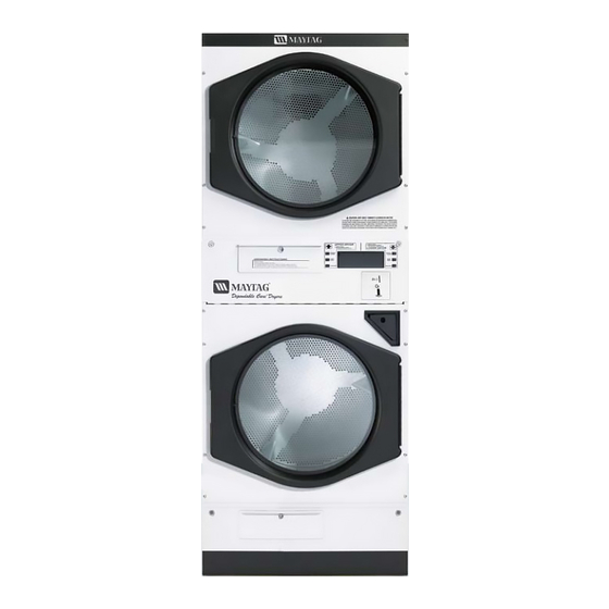
MLG32PDB
30 lb. Stacked Model
Installation Manual
RETAIN THESE INSTRUCTIONS IN A SAFE
PLACE FOR FUTURE REFERENCE
AVERTISSEMENT: Assurez-vous de bien
suivre les instructions données dans cette notice
pour réduire au minimum le risque d'incendie
ou d'explosion ou pour éviter tout dommage
matériel, toute blessure ou la mort.
— Ne pas entreposer ni utiliser d'essence ni
d'autres vapeurs ou liquides inflammables à
proximité de cet appareil ou de tout autre
appareil.
— QUE FAIRE SI VOUS SENTEZ UNE ODEUR
DE GAZ:
• Ne pas tenter d'allumer d'appareils.
• Ne touchez à aucun interrupteur. Ne pas
vous servir des téléphones se trouvant dans
le bâtiment.
• Évacuez la pièce, le bâtiment ou la zone.
• Appelez immédiatement votre fournisseur
de gaz depuis un voisin. Suivez les
instructions du fournisseur.
• Si vous ne pouvez rejoindre le fournisseur
de gaz, appelez le service des incendies.
— L'installation et l'entretien doivent être assurés par
un installateur ou un service d'entretien qualifié
ou par le fournisseur de gaz.
Part No. 113062
Advertisement
Table of Contents

Related Manuals for Maytag MLG32PDB


Summary of Contents for Maytag MLG32PDB
- Page 1 MLG32PDB 30 lb. Stacked Model Installation Manual WARNING: For your safety the information in AVERTISSEMENT: Assurez-vous de bien this manual must be followed to minimize the suivre les instructions données dans cette notice pour réduire au minimum le risque d’incendie risk of fire or explosion or to prevent property ou d’explosion ou pour éviter tout dommage...
- Page 2 Important For your convenience, log the following information: MLG32PDB DATE OF PURCHASE ________________________________ MODEL NO. __________________________________________ DEALER’S NAME __________________________________________________________________________________________ Serial Number(s)
-
Page 3: For Your Safety
IMPORTANT YOU MUST DISCONNECT AND LOCKOUT THE ELECTRIC SUPPLY AND THE GAS SUPPLY OR THE STEAM SUPPLY BEFORE ANY COVERS OR GUARDS ARE REMOVED FROM THE MACHINE TO ALLOW ACCESS FOR CLEANING, ADJUSTING, INSTALLATION, OR TESTING OF ANY EQUIPMENT PER OSHA (Occupational Safety and Health Administration) STANDARDS. - Page 4 WARNING The dryer must never be operated with any of the back guards, outer tops, or service panels removed. PERSONAL INJURY OR FIRE COULD RESULT. WARNING DRYER MUST NEVER BE OPERATED WITHOUT THE LINT FILTER/SCREEN IN PLACE, EVEN IF AN EXTERNAL LINT COLLECTION SYSTEM IS USED. IMPORTANT PLEASE OBSERVE ALL SAFETY PRECAUTIONS displayed on the equipment and/or specified in the installation manual included with the dryer.
-
Page 5: Table Of Contents
Table of Contents SECTION I IMPORTANT INFORMATION ................3 A. Receiving and Handling ....................... 3 B. Safety Precautions ........................4 SECTION II SPECIFICATIONS ..................... 6 A. Specifications ..........................6 SECTION III INSTALLATION PROCEDURES ................8 A. Unpacking/Setting Up ......................... 8 B. - Page 6 SECTION VII ROUTINE MAINTENANCE .................. 28 A. Cleaning ........................... 28 B. Adjustments ..........................29 C. Lubrication ..........................29 SECTION VIII DRYER DATA LABEL INFORMATION .............. 30 A. Data Label Location ......................... 30 B. Data Label ..........................31...
-
Page 7: Important Information
SECTION I IMPORTANT INFORMATION A. RECEIVING AND HANDLING The dryer is shipped in a protective stretch wrap cover with protective cardboard corners and top cover (or optional box) as a means of preventing damage in transit. Upon delivery, the dryer and packaging, and wooden skid should be visually inspected for shipping damage. -
Page 8: Safety Precautions
B. SAFETY PRECAUTIONS WARNING: For your safety, the information in this manual must be followed to minimize the risk of fire or explosion or to prevent property damage, personal injury, or loss of life. WARNING: The dryer must never be operated with any of the back guards, outer tops, or service panels removed. - Page 9 7. A program should be established for the inspection and cleaning of lint in the heating unit area, exhaust ductwork, and inside the dryer. The frequency of inspection and cleaning can best be determined from experience at each location. WARNING: The collection of lint in the burner area and exhaust ductwork can create a potential fire hazard.
-
Page 10: Specifications
SECTION II SPECIFICATIONS A. SPECIFICATIONS MLG32PDB MAXIMUM CAPACITY (DRY WEIGHT) 30 lbs BASKET (TUMBLER) DIAMETER 27-1/4” BASKET (TUMBLER) DEPTH 30” BASKET (TUMBLER) VOLUME (PER BASKET [TUMBLER]) 10.1 cu. ft. BASKET (TUMBLER) MOTOR (2 PLACES) 1/2 HP DOOR OPENING - DIAMETER (2 PLACES) 21-1/2”... - Page 11 Specifications MLG32PDB NOTE: Manufacturer reserves the right to make changes in specifications at any time without notice or obligation.
-
Page 12: Installation Procedures
SECTION III INSTALLATION PROCEDURES Installation should be performed by competent technicians in accordance with local and state codes. In the absence of these codes, the installation must conform to applicable American National Standards: ANSI Z223.1- LATEST EDITION (National Fuel Gas Code) or ANSI/NFPA NO. 70-LATEST EDITION (National Electrical Code) or in Canada, the installation must conform to applicable Canadian Standards: CAN/CGA-B149.1-M91 (Natural Gas) or CAN/CGA-B149.2-M91 (Liquid Propane [L.P.] Gas) or LATEST EDITION (for General Installation and Gas Plumbing) or Canadian Electrical Codes Parts 1 &... - Page 13 2. The dryer must not be installed or stored in an area where it will be exposed to water or weather. 3. The dryer is for use in noncombustible locations. 4. Provisions for adequate air supply must be provided as noted in this manual (refer to Fresh Air Supply Requirements in Section D).
-
Page 14: Dryer Enclosure Requirements
C. DRYER ENCLOSURE REQUIREMENTS Bulkheads and partitions should be made of noncombustible materials and must be located a minimum of 12-inches (18-inches or more is recommended for ease of installation, maintenance, and service) above the dryer outer top, except along the front of the dryer which may be closed in if desired. NOTE: Even though a minimum of 12-inches above the dryer outer top is acceptable, a clearance of 18-inches (or more) is suggested for ease of installation and service (electrical power connections). - Page 15 IMPORTANT: Make-up air openings should not be located near ductwork exhaust outlets. If make-up air openings are too close to the exhaust outlet, lint and fumes may be drawn back into the dryer area through these openings. NOTE: Component failure due to dry cleaning fumes will VOID THE WARRANTY.
-
Page 16: Exhaust Requirements
E. EXHAUST REQUIREMENTS Exhaust ductwork should be designed and installed by a qualified professional. Improperly sized ductwork will create excessive back pressure which results in slow drying, increased use of energy, overheating of the dryer, and shutdown of the burner by the airflow (sail) switches, burner hi-limits, or basket (tumbler) hi-heat thermostats. The dryer must be installed with a proper exhaust duct connection to the outside. - Page 17 NOTE: When the exhaust ductwork passes through a wall, ceiling, or roof made of combustible materials, the opening must be 2-inches larger than the duct (all the way around). The duct must be centered within this opening. NOTE: As per the National Fuel Gas Code, “Exhaust ducts for type 2 clothes dryers shall be constructed of sheet metal or other noncombustible material.
- Page 18 2. Multiple Dryer (Common) Venting If it is not feasible to provide separate exhaust ducts for each dryer, ducts from individual dryers may be channeled into a common main duct. The individual ducts should enter the bottom or side of the main duct at an angle not more than 45º...
- Page 19 IMPORTANT: DO NOT use screens, louvers, or caps on the outside opening of the exhaust ductwork. NOTE: In situations where a 10-inch exhaust duct is required or acceptable, to ease installation an 8-inch dryer exhaust outlet size to 10-inch exhaust duct increaser (transition piece) is available from the factory by ordering Part No.
-
Page 20: Electrical Information
F. ELECTRICAL INFORMATION 1. Electrical Requirements It is your responsibility to have ALL electrical connections made by a properly licensed and competent electrician to assure that the electrical installation is adequate and conforms to local and state regulations or codes. In the absence of such codes, ALL electrical connections, materials, and workmanship must conform to the applicable requirements of the National Electrical Code ANSI/NFPA NO. - Page 21 3. Electrical Connections A wire diagram is located on the inside of the control (service) box for connection data. a. Single-Phase (1Ø) Hookup The electrical connections on ALL single-phase (1Ø) dryers are made into the junction box located at the upper rear of the dryer. A separate circuit servicing each dryer basket (tumbler) must be provided. Single-Phase (1Ø) Electrical Connection Leads Black White...
- Page 22 Providing local codes permit, power to the dryer can be made by use of a flexible U.L. listed power cord or pigtail (wire size must conform to the rating of the dryer), or the dryer can be hard wired directly to the service breaker panel. In both cases, a strain relief must be installed where the wiring enters the dryer.
-
Page 23: Gas Information
The dryer must be connected to the type of heat or gas indicated on the dryer data label. If this information does not agree with the type of gas available, DO NOT operate the dryer. Contact the dealer who sold the dryer or contact Maytag Co. IMPORTANT: Any burner changes or conversions must be made by a qualified professional. - Page 24 2. Technical Gas Data a. Gas Specifications TYPE OF GAS NATURAL LIQUID PROPANE Manifold Pressure* 3.5 inches W.C. 10.5 inches W.C. In-Line Pressure 6.0 - 12.0 inches W.C. inches W.C. Orifice Size** Measured at gas valve pressure tap when the gas valve is on. ** For elevations up to 2,000 feet.
- Page 25 The size of the main gas supply line (header) will vary depending on the distance this line travels from the gas meter (or in the case of liquid propane [L.P.] gas, the supply tank), the number of tees, other gas-operated appliances on the supply line, etc. Specific information regarding supply line size should be determined by the gas supplier.
-
Page 26: Preparation For Operation
WARNING: Test ALL connections for leaks by brushing on a soapy water solution (liquid detergent works well). WARNING: NEVER TEST FOR LEAKS WITH A FLAME!!! It is important that gas pressure regulators meet applicable pressure requirements and that gas meters be rated for the total amount of appliance BTUs being supplied. - Page 27 NOTE: The dryer can be stopped at any time by opening the main door. To restart dryer, shut the main door and press desired fabric setting. 4) Open main door to stop the dryer, and change to a different fabric setting. Repeat this procedure, until ALL fabric selections have been tested.
-
Page 28: Shutdown Instructions
BASKET (TUMBLER) COATING The basket (tumbler) is treated with a protective coating. We suggest dampening old garments or cloth material with a solution of water and nonflammable mild detergent and tumbling them in the basket (tumbler) to remove this coating. 6. -
Page 29: Operating Instructions
SECTION IV OPERATING INSTRUCTIONS A. STARTING THE DRYER The dryer is available for use when the appropriate side of the microprocessor display reads “0 minutes” and the amount needed to start the dryer (i.e., “25”). Once the load has been put into the dryer and the main door is closed, start the dryer as follows: 1. -
Page 30: Service/Parts Information
1. Replacement parts should be purchased from the dealer from whom the Maytag equipment was purchased. If the dealer cannot be contacted or is unknown, contact the Maytag Co. for a dealer in your area. NOTE: When ordering replacement parts from the Maytag dealer or the Maytag Co. be sure to give them the correct model number and serial number so that your parts order can be processed in an expeditious manner. -
Page 31: Warranty Information
NOTE: Be sure to include the installation date when returning the warranty card(s). B. WARRANTY For a copy of the manufacturer’s commercial warranty covering your particular dryer(s), contact the Maytag dealer from whom you purchased the equipment and request a dryer warranty form. If the dealer cannot be contacted or is unknown, warranty information can be obtained from the Maytag Co. -
Page 32: Routine Maintenance
Maximum operating efficiency is dependent upon proper air circulation. The accumulation of lint can restrict this airflow. If the guidelines in this section are met, a Maytag dryer will provide many years of efficient, trouble free and most importantly safe operation. -
Page 33: Adjustments
DO NOT have a grease fitting. Provisions are made in the bearing housing for the addition of a grease fitting which can be obtained elsewhere, or from your Maytag dealer by ordering kit part no. -
Page 34: Dryer Data Label Information
SECTION VIII DRYER DATA LABEL INFORMATION A. DATA LABEL LOCATION The dryer data label is located in the upper basket (tumbler) gas train area (left middle section of dryer) as shown in the photo below. -
Page 35: Data Label
(i.e. type of gas and electric voltage, etc.). It also includes ALL the necessary data for technical support and parts information. When contacting the Maytag Co., please have the model and serial numbers available. This information is necessary to ensure proper service and parts information from the... - Page 36 THE DATA LABEL 1. MODEL NUMBER The model number is a Maytag Company number, which describes the size of the dryer and the type of heat (gas, electric, or steam). 2. SERIAL NUMBER The serial number allows the manufacturer to gather information on your particular dryer.
- Page 37 Part No. 113062 1 - 12/28/98-100 2 * 05/25/99-500 3 - 09/21/99-500 4 - 11/22/99-500 5 * 03/03/00-500 6 - 06/05/00-750 7 - 11/08/00-500 8 * 05/09/01-1,000 9 * 09/06/01-1,000 10 - 03/25/02-1,000 11 - 09/05/02-500 12 - 12/09/02-500 13 - 02/24/03-800 14 * 04/18/03-800...
Need help?
Do you have a question about the MLG32PDB and is the answer not in the manual?
Questions and answers