GE Digital Energy LP 11 Operating Manual
Uninterruptible power supply 3-5-6-8-10 kva
Hide thumbs
Also See for Digital Energy LP 11:
- Owner's manual and installation instructions (20 pages) ,
- Owner's manual and installation instructions (20 pages)

Related Manuals for GE Digital Energy LP 11


Summary of Contents for GE Digital Energy LP 11
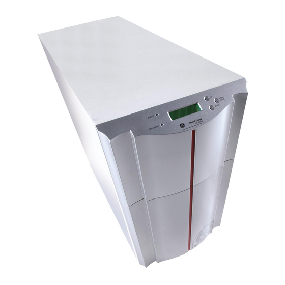
- Page 1 GE Consumer & Industrial Power Protection OPERATING MANUAL Digital Energy™ LP 11 Uninterruptible Power Supply 3-5-6-8-10 kVA...
- Page 2 The illustrations and plans describing the equipment are intended as general reference only and are not necessarily complete in every detail. The content of this publication may be subject to modification without prior notice. OPM_LPE_11X_3K0_10K_1GB_V041 GE DE LP 11 UPS: User manual 4.1 (GB)
-
Page 3: Table Of Contents
7.3 RPA-facility (Redundant Parallel Architecture) MAINTENANCE .......................31 8.1 General 8.2 Cooling fan 8.3 Batteries 8.4 Safety 8.5 Storage 8.6 Recycling the UPS at the end of service life TROUBLESHOOTING .....................32 SPECIFICATIONS....................33 APPENDIX: INSTALLATION DRAWINGS OPM_LPE_11X_3K0_10K_1GB_V041 GE DE LP 11 UPS: User manual 4.1 (GB) -
Page 4: Important Safety Instructions
By opening or removing covers you run the risk of exposure to dangerous voltages! While every care has been taken to ensure the completeness and accuracy of this manual, GE accepts no responsibility or liability for any loss or damage resulting from the use of the information contained in this document. -
Page 5: Storage
• Do not open or mutilate batteries: their contents may be extremely toxic. If exposed to electrolyte, wash immediately with plenty of water. • Proper disposal or recycling of the batteries is required. Refer to your local codes for disposal requirements. OPM_LPE_11X_3K0_10K_1GB_V041 GE DE LP 11 UPS: User manual 4.1 (GB) -
Page 6: Introduction
More than ever before, today's advanced electronic equipment, with complex integrated circuits and other sensitive electronics, needs a stable and continuous AC power supply to operate correctly. While the power coming from the wall outlet is often unreliable, a GE Digital Energy™ LP UPS provides the security of completely uninterrupted power. -
Page 7: Functional Explanation
SNMP CARD RELAY CARD OPTIONAL STANDARD FRONT INSTALLED: PANEL SYSTEM BATTERY ON/OFF RS232/ CONTACT BATTERY EXTENSION INTERFACE MICROPROCESSOR CONTROL Figure 3. Block diagram of the LP 11 UPS, utility failure OPM_LPE_11X_3K0_10K_1GB_V041 GE DE LP 11 UPS: User manual 4.1 (GB) -
Page 8: Automatic Bypass Switch
AUTOMATIC CHARGER RPA CARD BYPASS SWITCH SNMP CARD RELAY CARD OPTIONAL STANDARD FRONT INSTALLED: PANEL SYSTEM ON/OFF RS232/ BATTERY CONTACT EXTENSION INTERFACE MICROPROCESSOR CONTROL Figure 5. Bypass operation: manual bypass OPM_LPE_11X_3K0_10K_1GB_V041 GE DE LP 11 UPS: User manual 4.1 (GB) -
Page 9: Installation
The following sections describe the installation of the LP 11 UPS. LP 3/5/6-11 UPS: 4.5.1 and 4.5.2 LP 8/10-11 UPS: 4.5.3 and 4.5.4 LP 11 UPS, general: 4.5.5 OPM_LPE_11X_3K0_10K_1GB_V041 GE DE LP 11 UPS: User manual 4.1 (GB) -
Page 10: Lp 3/5/6-11: Standard Installation Procedure
(18) underneath the option slots. 11. Connect the utility power to the UPS. Figure 6. LP 3/5/6-11: 12. For a quick start proceed with section 5.2 ‘Start-up’. Standard installation procedure OPM_LPE_11X_3K0_10K_1GB_V041 GE DE LP 11 UPS: User manual 4.1 (GB) -
Page 11: Lp 3/5/6-11: Installation Of Digital Energy™ Lp Battery Extension Pack(S)
4.5.2 LP 3/5/6-11: installation of GE Digital Energy™ LP battery extension pack(s) The numbers between (brackets) refer to figures 12-13 in section 5.1. Battery extension pack(s) are shipped with all materials necessary to connect them to the UPS. The pack(s) can be connected to the DC connector (15) at the rear panel of the UPS. -
Page 12: Lp 8/10-11: Standard Installation Procedure
(18) underneath the option slots. see 4.5.5 / 7.3 11. Connect the utility power to the UPS. 12. For a quick start proceed with section 5.2 ‘Start-up’. Figure 8. LP 8/10-11: Standard installation procedure OPM_LPE_11X_3K0_10K_1GB_V041 GE DE LP 11 UPS: User manual 4.1 (GB) -
Page 13: Lp 8/10-11: Installation Of Digital Energy™ Lp Battery Extension Pack(S)
4.5.4 LP 8/10-11: installation of GE Digital Energy™ LP battery extension pack(s) The numbers between (brackets) refer to figures 12-13 in section 5.1. Battery extension pack(s) are shipped with all materials necessary to connect them to the UPS. The pack(s) can be connected to the DC connector (15) at the rear panel of the UPS. -
Page 14: Series: 2 / 3 / 4 Parallel Operating Units - Additional Info
Li/Lo: LENGTH OF I/O WIRING YELLOW NETWORK - EQUAL FOR EACH UPS CABLES AS DELIVERED - MINIMUM 3 METERS WITH THE UPS TO LOAD Figure 10. Installation of parallel operating LP 11 UPSs OPM_LPE_11X_3K0_10K_1GB_V041 GE DE LP 11 UPS: User manual 4.1 (GB) - Page 15 If the parameters mentioned in 4.5.5.1 step 6 are not set to the same value the UPS will display the following screen after start-up: AUTORESTART OFF SETTING MISMATCH In this case check and correct the setting of the parameters as mentioned in 4.5.5.1, step 6. OPM_LPE_11X_3K0_10K_1GB_V041 GE DE LP 11 UPS: User manual 4.1 (GB)
- Page 16 Separate the output of the UPS from the output junction (S1-4 in figure 10). To re-enter the unit into the system: 1. Reinstall the installation input fuse, 2. Connect the output of the UPS to the output junction, 3. Switch on the UPS. OPM_LPE_11X_3K0_10K_1GB_V041 GE DE LP 11 UPS: User manual 4.1 (GB)
-
Page 17: Operation
15 DC socket / connector. 16 Slots to fasten cable clamps. 17 Battery fuse holder. Figure 12. Front and rear panel 18 Holes to fasten data cables. top: LP 3/5/6-11 bottom: LP 8/10-11 OPM_LPE_11X_3K0_10K_1GB_V041 GE DE LP 11 UPS: User manual 4.1 (GB) - Page 18 18 Battery fuse holder(s) 7Ah: 2 fuses 14Ah: 4 fuses 19 Swivel to fasten cable in terminal cover of UPS Figure 13a. Rear panel battery extension pack (optional) equipped with swivel OPM_LPE_11X_3K0_10K_1GB_V041 GE DE LP 11 UPS: User manual 4.1 (GB)
-
Page 19: Start-Up
This way you ensure that the UPS can provide sufficient runtime in case of a mains power failure. If not yet switched on, the equipment connected to the UPS can be switched on now; operate as usual. OPM_LPE_11X_3K0_10K_1GB_V041 GE DE LP 11 UPS: User manual 4.1 (GB) -
Page 20: Use
(charging: + value, discharging: - value). 271V 1.9A The remaining battery runtime (or autonomy) during a mains failure. AUTONOMY TIME LEFT 10:30 OPERATING TIME The total operating time of the UPS. 0YEAR 29DAYS OPM_LPE_11X_3K0_10K_1GB_V041 GE DE LP 11 UPS: User manual 4.1 (GB) -
Page 21: Status And Alarm Menu
After 24 hours of charging time, the battery voltage did not reach the normal BATTERY CHARGER float voltage. This may be caused by faulty batteries, too many battery packs NO FLOAT connected or a charger fault. OPM_LPE_11X_3K0_10K_1GB_V041 GE DE LP 11 UPS: User manual 4.1 (GB) - Page 22 (see chapter 10). The remaining runtime. This figure is counted down during battery operation AUTONOMY TIME until either the mains returns or the batteries are depleted. LEFT 0:09:41 OPM_LPE_11X_3K0_10K_1GB_V041 GE DE LP 11 UPS: User manual 4.1 (GB)
-
Page 23: Service Menu
Default setting = 1 (active). For disabling this feature see 5.3.4. Start of the manual Quick Battery Test. QUICK BATTERY See for more information section 5.4.2 'Quick battery test' TEST PRESS ENTER OPM_LPE_11X_3K0_10K_1GB_V041 GE DE LP 11 UPS: User manual 4.1 (GB) - Page 24 Service set-up information about the auto-restart function. This function can AUTO RESTART be switched on or off by pressing ‘Enter/Reset’, depending on the actual ENTER/RESET CHNG status. See also 4.5.5.1 step 6. OPM_LPE_11X_3K0_10K_1GB_V041 GE DE LP 11 UPS: User manual 4.1 (GB)
-
Page 25: Set-Up Menu
The system can prompt for service to a user defined schedule. SERVICE WARNING Range: 8/12/16/20/24/28 months or DISABLED. To reset the timer: first select DISABLED “DISABLED” and subsequently set a new alarm interval. OPM_LPE_11X_3K0_10K_1GB_V041 GE DE LP 11 UPS: User manual 4.1 (GB) -
Page 26: Test Screens
NOTE: If the manual test is started immediately after installation or after a power failure, the UPS may generate a false 'replace battery' alarm as the batteries have been (partly) discharged during transport/storage or during the power failure. OPM_LPE_11X_3K0_10K_1GB_V041 GE DE LP 11 UPS: User manual 4.1 (GB) -
Page 27: Deep Battery Calibration Test
The test has been completed successfully TEST FAILED The test could not be executed properly: not all test conditions were fulfilled. The UPS system was not informed about the actual battery condition! OPM_LPE_11X_3K0_10K_1GB_V041 GE DE LP 11 UPS: User manual 4.1 (GB) -
Page 28: Other Features
'BATTERY DEPLETED' will be shown. The runtime is zero. 5.5.3 Sleep and wake-up GE Digital Energy™ UPS monitoring software allows you to program a 'sleep period' of the UPS by sending two commands to the UPS: - shut down after # minutes, and subsequently: - shut down during # hours. -
Page 29: Eco-Mode
Temperature compensated battery charging: This feature reduces the battery charge voltage with increasing temperature (-18mV/°C per 12V battery). As a result poor charging of the batteries under low temperature conditions and overcharging of the batteries under high temperature conditions are prevented. OPM_LPE_11X_3K0_10K_1GB_V041 GE DE LP 11 UPS: User manual 4.1 (GB) -
Page 30: Interfacing Features
When the mains power returns, the systems will automatically start up and will be up and running as soon as possible. For specific information on GE Digital Energy™ connectivity products please contact your dealer or internet: www.gedigitalenergy.com. -
Page 31: Optional Features
The RPA-facility allows to connect 2, 3 or 4 units in parallel. Connecting GE Digital Energy™ LP units in parallel is attractive for several reasons. Redundancy: To achieve the highest possible level of power protection in a fault-tolerant network. -
Page 32: Maintenance
It does not contain CFCs (Carbon Fluorine Chloride) of HCFCs (Halogen Carbon Fluorine Chloride). GE Digital Energy, in compliance with environment protection recommends that the UPS equipment, at the end of its service life, must be recycled conforming to the local applicable regulations. -
Page 33: Troubleshooting
UPS to save battery power. If the UPS input power is absent for several days and the UPS remains on under no-load conditions, the batteries can be discharged very deeply, resulting in a short battery life time. OPM_LPE_11X_3K0_10K_1GB_V041 GE DE LP 11 UPS: User manual 4.1 (GB) -
Page 34: Specifications
Automatic shut down (or transfer to bypass, if bypass is available) in case of - low/high DC voltage - overtemperature - overload / short circuit The output is protected against connection to the mains * according to EN 50091-1 OPM_LPE_11X_3K0_10K_1GB_V041 GE DE LP 11 UPS: User manual 4.1 (GB) - Page 35 110kg 115kg 165kg 170kg GENERAL DESIGN CRITERIA Mechanical IP20 Humidity 95% non condensing Safety EN 50091-1; EN 60950; IEC 950 EN 50091-2 Surge capability IEC 1000-4-5 (6kV 1.2/50µs, 3kA 8/20µs) OPM_LPE_11X_3K0_10K_1GB_V041 GE DE LP 11 UPS: User manual 4.1 (GB)
- Page 36 Option slot (middle) optional plug-in SNMP Card or optional Relay Card Option slot (right) optional plug-in RPA-Card (Redundant Parallel Architecture) Emergency shutdown connection Battery extension signal connection I/O terminals OPM_LPE_11X_3K0_10K_1GB_V041 GE DE LP 11 UPS: User manual 4.1 (GB)
- Page 37 LP 3/5/6-11 installation drawing Model Heat dissipation Dimensions Weight Air flow Amb. Rel. Altitude Branch Input/output Minimum free space Bottom 100% load 50% load 100% temp. humidity (max 4000m) protection wiring required load non-cond. slow front side rear Btu/hr Btu/hr m3/hr °C 3-11...
- Page 38 LP 8/10-11 installation drawing Model Heat dissipation Dimensions Weight Air flow Amb. Rel. Altitude Branch Input/output Minimum free space Bottom 100% load 50% load 100% temp. humidity (max 4000m) protec- wiring required load non-cond. tion front side rear slow Btu/hr Btu/hr m3/hr °C...
Need help?
Do you have a question about the Digital Energy LP 11 and is the answer not in the manual?
Questions and answers
How to configure output for Lp8-11 to get 240 v