Table of Contents
Advertisement
Quick Links
Advertisement
Table of Contents

Subscribe to Our Youtube Channel
Related Manuals for AirLive VoIP 400 Series


Summary of Contents for AirLive VoIP 400 Series
- Page 1 VoIP 400 Series VoIP Gateway Router User’s Guide...
-
Page 2: Fcc Notice
ITG User’s Guide FCC Notice This equipment has been tested and found to comply with the limits for a Class B digital device, pursuant to Part 15 of FCC Rules. These limits are designed to provide reasonable protection against harmful interference when the equipment is operated in a commercial environment. -
Page 3: How To Use This Manual
ITG User’s Guide How to Use This Manual This manual was designed for the non-technical users of the Internet telephony gateway (ITG). It contains information about the functions operation and basic instructions for its installation. Chapter 1: Overview This chapter provides conceptual overview and description of the ITG, explanation of how the ITG interacts with each for enabling VoIP services, and an overview of the required tasks Chapter 2: Installing the ITG This chapter describes required steps to properly and safely install and configure the ITG on... -
Page 4: Important Safety Instructions
ITG User’s Guide Important Safety Instructions Before plug into electrical outlet, carefully read installation instructions in Chapter 2. For your own safety and the safety of your equipment, always take the following precautions: Follow instructions and warnings in the documentation. ‧... -
Page 5: Documentation Abbreviations
ITG User’s Guide Documentation Abbreviations Throughout this guide, the user will come across a number of abbreviations that are common throughout the industry. The user should be familiar with the following abbreviations: ATPM Address Translation and Parsing Manager Command Line Interface Digital Signal Processor DTMF Dual Tone Multi-Frequency... -
Page 6: Notation Conventions
ITG User’s Guide Notation Conventions Throughout this guide, different type styles and characters are used. These serve a variety of purposes as described below: Convention Description boldface Commands and keywords are in boldface. italic Arguments for which you supply values are in italics. courier Messages that the ITG CLI displays are in plain courier font. -
Page 7: Table Of Contents
ITG User’s Guide Table of Contents Chapter 1 Overview Features Networking Protocols Package Contents Front Panel LED Indicators Reset Button Rear Panel LAN / Console Ports Chapter 2 Installing the ITG Network Requirements Installing the ITG Connecting to the telephony devices Connecting to the Network Providing Power to the ITG Assigning IP address to the ITG... - Page 8 ITG User’s Guide Chapter 5 Making a Call with ITG Making a call with ITG FXS Module Making a call with ITG FXO Module Making a call with ITG Application Sample Chapter 6 Application Samples Module Configuration Chapter 7 Troubleshooting Tips Appendix A Worksheets A.1 IP Parameters...
-
Page 9: Chapter 1 Overview
ITG User’s Guide Chapter 1 Overview This chapter gives an overview of the 2 ports & 4 ports desktop version Internet Telephony Gateway (ITG) and a detailed description of its front panel and rear panel. Features The ITG is a cost-effective and highly reliable analog Voice over IP (VoIP) Gateway that offers toll quality... -
Page 10: Front Panel
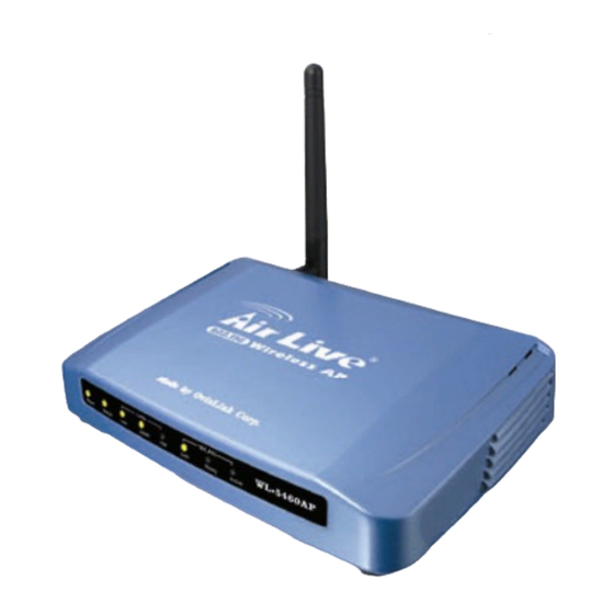
ITG User’s Guide The contents of your product should contain the following items: Internet Telephony Gateway 2 port or 4 port desk top version 100-240V Power Adapter 9-pin straight through RS-232 cable User’s guide Front Panel The front panel of the ITG contains a push button and LED indicators. The following figure illustrates the front panel of the ITG. -
Page 11: Reset Button
ITG User’s Guide SYSTEM Green Blinking The system is running. (Heartbeat LED) Green Data is presented on LAN. The gateway is connected to LAN at 100Mb/s. 100M Green The gateway is connected to LAN at 10Mb/s. Green The gateway is connected to LAN. Green Data collision is occurring on the network connection. - Page 12 ITG User’s Guide interface port, there is a 9-pin RS-232 interface port on the rear panel. Their functions are described below: Port Label Function RJ45 Connecting the ITG to a 10/100 Mbps Ethernet network Connecting the ITG to a VT-100 terminal or terminal 9-pin RS-232 User Console emulator for configuring the ITG...
-
Page 13: Chapter 2 Installing The Itg
ITG User’s Guide Chapter 2 Installing the ITG This chapter gives information on how to install the ITG. Network Requirements For the ITG to successfully operate in your network, your network must meet the following requirements: A working 10/100 Base-T Ethernet. The ITG connects to Internet via an Ethernet LAN. IP network that supports gateway, and subnet mask. -
Page 14: Assigning Ip Address To The Itg
ITG User’s Guide Connect one end of the power adapter that came with the ITG to the power receptacle on the rear panel. Connect the other end of the power adapter to an AC power outlet. The ITG will execute the memory testing and application code automatically.. Assigning IP address to the ITG The IP address is the unique logical address identifying each IP node, such as the ITG, on an IP network. -
Page 15: Chapter 3 Itg Concepts
ITG User’s Guide Chapter 3 ITG Concepts The ITG enables the transmission of voice and fax traffic over any IP network by digitizing voice and fax signals, encapsulating the information within IP packets, and then sending the packets across the IP network How the ITG Operates The TIM inside the ITG digitizes analog voice signals at 8 Kbps. -
Page 16: Dial Plan (Fxo2S2)
ITG User’s Guide might have 20 people who can handle support calls. Access to customer support is through a single phone number but the next available support person is actually connected upon each incoming call. These 20 phones would be configured as a hunt group. -
Page 17: Destination Table
ITG User’s Guide Destination Table The destination table maps a destination to a telephony port or the IP address of a remote ITG. Destination table sample Dest id Mode Destination ------------------------------------------------------- Local PORT = 0 Local PORT = 2 Local PORT = 3 H.323 Dest = 192.168.0.55/1720 TCP... -
Page 18: Chapter 4 Configuring Itg From A Web Browser
ITG User’s Guide Chapter 4 Configuring ITG from a Web Browser This chapter explains procedures for configuring the ITG from the web browser. Http setting mode This section describes the processes for setting up Internet Telephony Gateway once it has been installed. - Page 19 ITG User’s Guide Specify an IP address set ON. ‧ IP Address: 192.168.0.2 ‧ Subnet Mask: 255.255.255.0 ‧ Restart your PC and Start your WEB browser. 6. In the Address box, enter the following: HTTP://192.168.0.1 (This is a default IP in the gateway from factory) 7.
- Page 20 ITG User’s Guide 2.View System Configurations, which includes the specific information related to version, network, H.323, coder, and the channel of the gateway you are using. 3.Configure System Settings, which allows you to modify the system parameters as you wish. Select Main Menu\Dial Plan Settings , we can find the following Dial Plan Menu.
- Page 21 ITG User’s Guide We can add (delete, find or list) desired telephone number mapping to hunt group at this menu. Telephone Number Telephone number to match. This is only part of the total dialed string. Hunt Group ID For each hunt group ID, you need to assign it a unique identifier between 0 and 99.
- Page 22 ITG User’s Guide We can add (delete, find or list) desired hunt group ID mapping to destination ID at this menu. Please select Main Menu\Dial Plan\Phone/Hunt Group/Destination Settings, we can find Phone/Hunt Group/Dest. Setting Menu. We are doing the ITG destination table management. One is Remote Destination IP and the other is Local Destination Channel.
- Page 23 ITG User’s Guide This Common Parameter Settings is the same as previous ATPM system parameters description. . Please select Main Menu\Dial Plan\Clear All Dial Plan Settings Clear All Dial Plan Settings will clear all the settings you made before. However, the 'Clear All' is only temporary if you do not store to the Flash Memory afterwards.
- Page 24 ITG User’s Guide Please Back To Main Menu Please select Main Menu\View System Config. View System Config. Function Briefings. Five options available 1.Firmware Version Information, which shows the versions of each firmware component 2.Network Settings, which shows the IP-related settings, and the status of associated management tools 3.H.323 Parameter Settings, which shows the H.323-related parameters associated with the gateway...
- Page 25 ITG User’s Guide h323 h245_term_type = 60 h323 rtp_port_base = 30000 h323 out_fast_start = off h323 in_fast_start = off h323 h245_tunneling=off h323 cisco_t38=on h323 callSignalPort=1720 h323 nat_call = on h323 call_name= h323 local_alert=off h323 default_dtmf = H323 V2 Signal No Alternate IP Defined! h323 dns_ip = 0 h323 gk_mode = off h323 h245_timeout = 30000...
- Page 26 ITG User’s Guide This command can show the desired TCID setting of ITG, value is from 0 to 1 for 2 ports ITG and 0 to 3 for 4 ports ITG. Please refer the appendix C to find the factory default setting. Please Back To Main Menu Please select Main Menu\Configure System Settings System Config.
- Page 27 ITG User’s Guide Please select Main Menu\Configure System Settings\ITG IP Settings This screen can setup your ITG IP Address, Subnet Mask and Default IP Gateway Address. These values will be valid after ITG reboot. Please select Main Menu\Configure System Settings\H.323 Parameter Settings There are H.323 General Parameter Settings, H.323 GateKeeper Settings, H.323 Aliases Settings.
- Page 28 ITG User’s Guide 1. Display Name: The default string is “Customer”. This field is to set the display name information that is carried in the H.323 setup messages. Up to 48 characters can be entered. 2. Terminal Type: The default value is 60. This field is to set the H.245 terminal type, which is used as part of the master/slave determination process of H.245.
- Page 29 ITG User’s Guide 1.Gate Keeper Mode: The default setting is off. This field is to select the co-operation mode with some gatekeeper(s). Three options available: - off: disables gatekeeper co-operation, - auto: enables auto-discovery of the gatekeeper, - manual: enables gatekeeper co-operation in manual operation (the gatekeeper address must be properly assigned).
-
Page 30: Web Browser Setting Sample
ITG User’s Guide Web Browser setting sample This section describes how to use web browser to build a sample scenario dial plan in ITG. We suggest some steps to setup dial plan at web browser setting, 1. Please draw down scenario to have a VoIP call application 2. - Page 31 ITG User’s Guide 2. Key-in IP Address: 192.168.0.20, Subnet Mask: 255.255.255.0 and Default IP Gateway Address: 0.0.0.0 in the related fields. 3. And push “Save The Change” button Local gateway: local telephone number setup Gateway A FXO to PBX’s extension number 8XX setting. 8XX locates at PBX side and via Port 0 of FXO, we can access PBX’s extension.
- Page 32 ITG User’s Guide 2. Push “Complete” button. And screen will show “List All Hunt Group IDs Result:” table. 3. Purpose: add hunt group to destination ID mapping table of phone number 8 into dial plan Back To Dial-Plan Menu 1. Please select “Main Menu\ Dial Plan\ Phone/Hunt Group/Destination Settings\ Phone/Hunt Group/Dest.
- Page 33 ITG User’s Guide 2. Push “Complete” button. And screen will show “Telephone Number Added 201 OK” table. Telephone number 201 is added in gateway dial plan. 3. Purpose: add telephone address to hunt group mapping table of phone number 201 into dial plan Back To Dial-Plan Menu 1.
- Page 34 ITG User’s Guide 2. Push “Complete” button. And screen will show “Add Destination ID Result:” table The Destination ID 3 is bound to local channel 2. 3. Purpose: add destination ID to Local channel number mapping table of phone number 201 into dial plan Back To Dial-Plan Menu Gateway A’s telephone number 301 setting.
- Page 35 ITG User’s Guide 2. Push “Complete” button. And screen will show “List All Hunt Group IDs Result:” table. 3. Purpose: add hunt group to Local channel number mapping table of phone number 301 into dial plan Back To Dial-Plan Menu 1.
- Page 36 ITG User’s Guide 1. Please select “Main Menu\Dial Plan\Phone/Hunt Group/Destination Settings\Phone/Hunt Group/Dest. Setting Menu” from Main Menu 2. Key-in 20, and related information in each field. 3. Push “Complete” button. And screen will show “Telephone Number Added 20 OK” table. Remote ID number 20 is stored in gateway dial plan.
- Page 37 ITG User’s Guide Back To Dial-Plan Menu 1. Please select “Main Menu\ Dial Plan\ Phone/Hunt Group/Destination Settings\ Phone/Hunt Group/Dest. Setting Menu\ Add Remote_Destination_IP” from Main Menu 2. Push “Complete” button. And screen will show “Add Destination ID Result: The Destination ID 11 is bound to IP address 192.168.0.55 for H.323 VoIP application.”...
- Page 38 ITG User’s Guide Local gateway: local telephone number setup Gateway B’s telephone number 550 setting. 550 locates at Port 0 of 2 ports ITG 1. Please select “Main Menu\ Dial Plan\ Phone/Hunt Group/Destination Settings\ Phone/Hunt Group/Dest. Setting Menu\ Add Telephone” from Main Menu 2.
- Page 39 ITG User’s Guide 2. Push “Complete” button. And screen will show “List All Hunt Group IDs Result:” table. 3. Purpose: add hunt group to destination ID mapping table of phone number 550 into dial plan Back To Dial-Plan Menu 1. Please select “Main Menu\ Dial Plan\ Phone/Hunt Group/Destination Settings\ Phone/Hunt Group/Dest.
- Page 40 ITG User’s Guide Back To Dial-Plan Menu 1. Please select “Main Menu\ Dial Plan\ Phone/Hunt Group/Destination Settings\ Phone/Hunt Group/Dest. Setting Menu\ Add Hunt Group” from Main Menu 2. Push “Complete” button. And screen will show “List All Hunt Group IDs Result:” table. 3.
- Page 41 ITG User’s Guide Local gateway: remote gateway IP & remote telephone number setup Gateway B’s remote gateway IP & remote telephone number 301 & 201 & 800 & 801 setting Back To Dial-Plan Menu Remote Gateway ID number setting. Due to 10 is remote gateway A ID. Due to 301 & 201 & 800 &...
- Page 42 ITG User’s Guide Back To Dial-Plan Menu 1. Please select “Main Menu\ Dial Plan\ Phone/Hunt Group/Destination Settings\ Phone/Hunt Group/Dest. Setting Menu\ Add Hunt Group” from Main Menu 2. Push “Complete” button. And screen will show “List All Hunt Group IDs Result:” table. 3.
- Page 43 ITG User’s Guide Please select “Main Menu\ Dial Plan\ Phone/Hunt Group/Destination Settings\ Phone/Hunt Group/Dest. Setting Menu\ List Hunt Group” from Main Menu, we can list the above hunt group setting. Please select “Main Menu\ Dial Plan\ Phone/Hunt Group/Destination Settings\ Phone/Hunt Group/Dest.
-
Page 44: Chapter 5 Making A Call With Itg
ITG User’s Guide Chapter 5 Making a Call with ITG This chapter how to make phone calls from telephony devices connected to the ITG directly or indirectly. Making a call with ITG FXS Module ITG has two slide-in modules. FXS module can connect to analogue phone directly, and FXO module can connect to PBX. -
Page 45: Making A Call With Itg Application Sample
ITG User’s Guide 3. When the ITG is connected, the related LED will be lighted green. For Example: If the telephone set is connected to the second port of FXO. When the PBX is connected to ITG FXO port, the second LED will be green. We can dial the desired destination phone number on the telephone set. - Page 46 ITG User’s Guide Gateway B, 2 ports ITG, is configured as following: 1. Gateway B IP: 192.168.0.55, mask IP: 255.255.255.0, gateway IP 0.0.0.0 (virtual IP) 2. GW B ID=20 3. Port 0 of FXS has a telephone set connected, its phone number is 550 Port 1 of FXS has a telephone set connected, its phone number is 551 Gateway A and Gateway B dial plan setting Gateway A address translation table...
- Page 47 ITG User’s Guide ITGB destination table Dest id Mode Destination ------------------------------------------------------- Local PORT = 0 Local PORT = 1 H.323 Dest = 192.168.0.20/1720 TCP Making a call between gateway A and Gateway B Case 1: Gateway Phone to Gateway Phone, Gateway B phone 550 calls to Gateway A phone 201 Human operation at GW B Equipment operation...
- Page 48 ITG User’s Guide Ring back tone is heard Phone 12345678 is ringing Phone 12345678 picks up Enjoy VoIP Enjoy VoIP The above process is the same as Gateway A phone 201 (301) calls to phone A number (03) 12345678 Case 3: PSTN Phone to Gateway Phone, Phone A number (03) 12345678 calls to Gateway B phone 551 Human operation at Equipment operation...
-
Page 49: Chapter 6 Application Samples
ITG User’s Guide Chapter 6 Application Samples This section discusses the various environments and situations where you can use the Internet Telephony Gateway. Module Configuration Internet Telephony Gateway supports FXS and FXO modules. FXS (Foreign Exchange Station) FXS provides power and ringing signals to its interfacing equipment. It is not intended for connection to the Public Switched Telephone Network. - Page 50 ITG User’s Guide Application A: FXS Application-A has two possible connections. The A-1 connection shows the connection between the gateway to telephone set (POTS) or FAX machine. The FXS module is used in the A-1 connection. The other connection A-2, on the right hand side, is used to connect the gateway and PBX that has the CO trunk interface.
- Page 51 ITG User’s Guide Application B: FXS / FXO combination Application-B has three possible connections. The B-1 connection is a normal trunk connection between the CO switch and PBX. The B-2 connection is identical to the A-1 connection mentioned in Application A. The B-3 connection is used to connect the PBX and gateway through the internal analogue lines provided by the PBX.
-
Page 52: Chapter 7 Troubleshooting Tips
ITG User’s Guide Chapter 7 Troubleshooting Tips This section provides solutions for problems you may possibly encounter while installing and connecting your Internet Telephony Gateway. Power (PWR) LED is not illuminate 1. Check the power adapter connection. 2. If the power adapter or power cord is connected to the gateway, check that the cord is securely plugged into the power socket on the rear of the console. - Page 53 ITG User’s Guide 2. Check the destination ITG and phone is available Final Steps If the procedures in this section have not solved the problem, reset the gateway several times by turning the power on and off. If the problem still exists, contact customer support.
-
Page 54: Appendix A Worksheets
ITG User’s Guide Appendix A Worksheets A.1 IP Parameters IP address IP subnet mask Default gateway A.2 ATPM Address Table Min. # of Max. # of Digits Digits Digits to Digits to Match Hunt Prefix String Collect Collect Strip Group Command Line Interface... -
Page 55: A.3 Atpm Hunt Group Table
ITG User’s Guide A.3 ATPM Hunt Group Table Hunt Type Hunt Group ID List of Destination IDs Command Line Interface... -
Page 56: A.4 Atpm Destination Table
ITG User’s Guide A.4 ATPM Destination Table Local Destinations Port# Mode Destination ID port port port port Remote Destinations Destination ID Mode IP address IP port H323 or DNS (optional) Command Line Interface...
Need help?
Do you have a question about the VoIP 400 Series and is the answer not in the manual?
Questions and answers