
Related Manuals for Caple C993I


Summary of Contents for Caple C993I
- Page 1 Instruction manual for induction hob Model code: C993I Contact Caple on 0844 800 3830 or for spare parts www.4caple.co.uk...
-
Page 2: Control Description
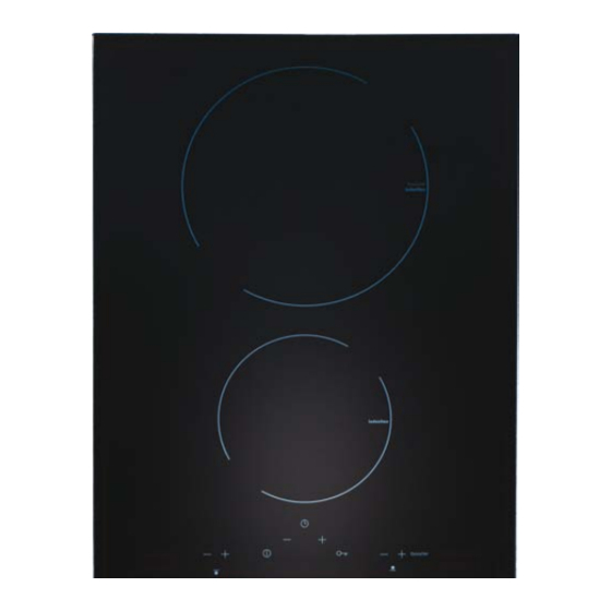
DESCRIPTION C933I DIMENSIONS: 385 X 525 Booster 1 - Cooking area Ø 145 (1600 W) 2 - Cooking area Ø 210 (2000 W - Booster "P" 3000 W) CONTROL DESCRIPTION Booster Switching on - switching off Controls functions lock Cooking area directions Cooking area controls Cooking area timer checks Cooking area power indicator... - Page 3 SAFETY AND CARE DIRECTIONS Correct use surface of the hob. Also grains of sand could cause scratches. • To avoid damages to persons and fittings please • Make sure that sugar, liquefied or solid, plastic read this manual carefully before using the hob for or silver paper are not leant on the hot cooking the first time.
- Page 4 For this purpose do not hold the wire but the plug, if present. Call the Caple service centre. Pay attention not to connect the appliance to the electrical system before repairing it.
-
Page 5: Installation
INSTALLATION General Instructions non-stationary places, like for example a ship, can be installed only by skilled technicians to • The installation and the connection must guarantee safety during the functioning. be done only by a qualified electrician. • If under the appliance there is a drawer, do not Refer only to an electrician who knows local store flamable object inside of it (i.e. - Page 6 INSTALLATION CUT-OUT DIMENSIONS VERSION 380 X 520: 350 (A) X 495 (B) HEIGHT OF ELECTRICAL CONNECTION BOX: H=75 mm • Make the cut-out on the work surface according to the model dimensions (see pictures above). • Respect the minimal distance of 50 mm towards the back side and on the right and left towards a possible lateral wall.
-
Page 7: Electrical Connection
INSTALLATION ATTENTION: To guarantee a correct functioning of the appliance it is important to provide the work surface, during the installation, of a 4mm space for the length of the recess on the front side of the furniture. This, because the electrical controls have a guard which, if the electronic system exceeds a 85°C temperature, switches off 50 min. -
Page 8: Start-Up And Use
START UP AND USE Practical advice for appliance use. To obtain the best performance from your hob: • Use flat bottom pots with elevated thickness, to • Use cooking vessels made from material that be sure that these perfectly adhere to the heating is compatible with the induction principle areas. - Page 9 START UP AND USE The hob switches on selecting the sensor on the controls area. When this sensor is selected a sound is uttered. Disconnect the key selecting the sensor. Booster Booster The heat areas switch on and all stay at “0” until a power level is selected. If this does not succeed in 10 seconds, the hob automatically switch off.
- Page 10 START UP AND USE Automatic switch-off. If during the functioning the power level is not changed, for safety reasons the cooking areas authomatically switch off after a time indicated in the table below: POWER LEVEL MAX. TIME ON (HOURS) 10 (minutes) The cooking area can be switched off also manually pushing simultaneously on (+) and (-) sensors or bringing the (-) sensor to "0"...
- Page 11 START UP AND USE Operating the timer The timer is activated by pressing the timer keys (+) or (-). The timer value can be selected between 1 and 99 minutes, and can be modified at any time. To cancel the operation of the timer, select a timer value of <00> using the sensor (-), or switch off the timer by pressing the corresponding sensors (+) and (-) at the same time.
- Page 12 START UP AND USE Change the setting of the Timer When the timer is running, you can change at any time before the scheduled time by tapping the keys (+) or (-). The countdown will stop waiting for the new setting. End of countdown timer When the timer has reached the end of the allotted time, the timer display will flash and the cooking area is brought to the value "0".
-
Page 13: Problems And Solutions
PROBLEMS AND SOLUTIONS Below are listed some possible fault messages Afterheat: for which it is necessary to seek technical support. For safety reasons these information are the most important. Cooking zone temperature sensor: • If the hob is switch off, the zones which show the power are fixed on “H”. -
Page 14: Environment Protection
ENVIRONMENT PROTECTION This product complies with EU Directive 2002/96/EC. The crossed-out dustbin symbol reported on the appliance indicates that the appliance must be disposed of separately from other domestic refuse at the end of its useful life. It must therefore be delivered to a waste recycling centre specifi cally for electric and electronic equipment or returned to the retailer at the moment of purchase of a new equivalent appliance. - Page 16 The manufacturing firm refuses all responsibility for any possible imprecision in this booklet, due to misprints or clerical errors. It reserves the right to make all the changes that it will consider necessary in its own products, without affecting the essential characteristics of functionality and safety.
Need help?
Do you have a question about the C993I and is the answer not in the manual?
Questions and answers