Table of Contents
Advertisement
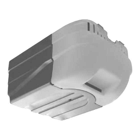
GCG , PCG, H
Series
Includes
and SERIES II Electronics
Included Wall Control MUST be installed prior to operation of this Garage
Door Operator
®
Safe-T-Beam
Safety Reverse System Must be installed to close door
NOTE: Your Residential Operator comes with a Rail Assembly which is
standard for up to a 7 foot 6 inch high door. An extension kit for an 8 foot
high door is available.
For Answers and Assistance:
1.800.354.3643
or visit www.geniecompany.com
SAVE THIS MANUAL FOR FUTURE REFERENCE
3452535556
Remote Control
®
Advertisement
Table of Contents

Related Manuals for Genie H


Summary of Contents for Genie H
-
Page 1: Remote Control
GCG , PCG, H Series Includes and SERIES II Electronics Included Wall Control MUST be installed prior to operation of this Garage Door Operator ® Safe-T-Beam Safety Reverse System Must be installed to close door NOTE: Your Residential Operator comes with a Rail Assembly which is standard for up to a 7 foot 6 inch high door. -
Page 2: Pre-Installation Checklist
The Genie Company recommends that you read and fully understand all information and instructions contained herein before choosing a “Do-it-yourself” installation. Any questions should be directed to the Genie Company or an authorized Genie Dealer. ( The issue numbers below refer to the circled numbers in the illustrations on page 3. -
Page 3: Typical Sectional Door Installation
TYPICAL SECTIONAL DOOR INSTALLATION TYPICAL SUPPORT BRACKET 48" POWER CORD 120V GROUNDED OUTLET EXTENSION SPRING TORSION SPRING TYPICAL 1-PIECE DOOR INSTALLATION FOR HELP-1.800.354.3643 OR GENIECOMPANY.COM ADDED HEADER BRACKET MOUNTING BOARD SAFE-T-BEAM ® SECTIONAL DOOR 1-PIECE DOOR BRACES... -
Page 4: Table Of Contents
TABLE OF CONTENTS SECTION ......... PAGE PRE-INSTALLATION CHECKS . -
Page 5: Recommended Tools
RECOMMENDED TOOLS Drill 5/32" Drill Bit Step ladder PARTS IDENTIFICATION - Not Shown Full Size . #6 x 1-1/4" Pan Head Phillips Wall console Screw #6 x 1-1/4" Pan Source STB Head Phillips (Red LED) Screw Wall button FASTENERS - Shown Full Size . - Page 6 1-PIECE RAIL HARDWARE EXPLODED VIEW [ 2 ] 3-PIECE RAIL HARDWARE EXPLODED VIEW [ 4 ] FOR HELP-1.800.354.3643 OR GENIECOMPANY.COM...
-
Page 7: Safety Information
If you have questions or do not understand the information presented, contact The Genie Company or an authorized Genie Dealer. In this section and those that follow, the words Danger, Warning, and Caution are used to emphasize important safety information. -
Page 8: Assembly
OPERATOR ASSEMBLY RAIL ASSEMBLY: Use a clean, flat surface. CAUTION Drive chain can slide out of rails. Do not run until operator is fully assembled. NOTE: For 1-piece rail—skip to step 4. 1. Identify the rail sections (Fig. 1-1). • First rail section (attaches to power head). –... - Page 9 CAUTION Make sure that the carriage magnet is in place in the top of the carriage slide. 5. Slip carriage into carriage slot of rail. • Flip the rail assembly up side down. • Place emergency release lever in “release” position (See below).
- Page 10 9. Attach limit switches. 2 switches included, “CLOSE” limit switch (brown wire) and “OPEN” limit switch (white wire) (Fig. 1-10). • Turn set screws (39) into threaded holes, just enough so screw stays in place. (Fig. 1-10). [ 39 ] •...
-
Page 11: Installation
To reduce the risk of severe injury or death: 1. READ AND FOLLOW ALL SAFETY, INSTALLATION AND OPERATION INSTRUCTIONS. If you have questions or do not understand an instruction, call The Genie Company or an authorized Genie Dealer. 2. Do Not install operator on an improperly balanced door. -
Page 12: Door Bracket
Contact door manufacturer or distributor for a bracing kit. The Genie Company is not responsible for damage caused due to improperly braced door (Fig. 2-6). 3. Finding door bracket mounting location. -
Page 13: Mounting The Operator
MOUNTING THE OPERATOR: 1. Getting Started. • Position rail/power head assembly (Fig. 2-7). – Rail strap leaning on wall next to header bracket. – Place material on floor under power head to protect from scratching. (A box, stool, or similar device may be needed to clear a torsion spring, as shown.) 2. - Page 14 INSTALL DOOR ARMS: OPEN YELLOW PARTS BAG 1. Attach the arms. • Fasten curved door arm to door bracket using clevis pin (24) and cotter pin (25) (Fig. 2-10). • Straight arm to carriage using clevis pin (24) and cotter pin (25) (Fig. 2-10). [24] 2.
-
Page 15: Electrical Installation
® SAFE-T-BEAM SYSTEM INSTALLATION WARNING There should be no electrical power to the operator while installing Safe-T-Beam System have plugged in the power cord—UNPLUG IT NOW. NOTE: The operator will not close the door automatically unless the Safe-T-Beam installed. 1. Mounting brackets. •... - Page 16 OPEN RED PARTS BAG 3. Wiring (cont’). • Securely fasten wires to wall as you go. – Use insulated staples (included). – Staples should be snug only. CAUTION Staples which are too tight can cut or pinch wires. Cut or pinched wires can cause the “STB”...
-
Page 17: Wall Control Installation
WALL CONTROL INSTALLATION WARNING Verify there is no power to the operator before installing wall control wires. CAUTION Use of any wall control other than the type supplied will prevent the light from working and could cause the door to operate on its own. Cut or pinched wires can cause the wall control to stop working. -
Page 18: Connect Operator To Power
• Replace motor cover and re-energize the circuit. 2. Check Safe-T-Beam alignment (Fig. 6-3). ® NOTE: The Genie Company is not responsible for charges resulting from work performed by an independent electrician. FOR HELP-1.800.354.3643 OR GENIECOMPANY.COM FIG. 6-1 Removing motor cover. - Page 19 LIMIT SWITCH / FORCE ADJUSTMENT WARNING DOOR OPENS RAPIDLY Keep the path clear Position the ladder to the side of the power head so it is clear of all moving parts of the operator and door. Always set the door operator to the minimum force required to operate the door NOTE: During operator cycling for force adjustment, the motor protector may shut off...
-
Page 20: Adjustments
CONTACT REVERSE TEST The force adjustments and limit switch settings MUST BE COMPLETED before testing contact reverse. 1. Testing. • Open garage door using wall control. – Place a 2" x 4" board (laid flat) under center of garage door opening (Fig. 7-5). –... -
Page 21: Lost Or Stolen Remote
MULTI-BUTTON REMOTE 1. Programming. NOTE: Each button on a multi-button remote is designed for use with 1 door. You cannot pro- gram 2 buttons to operate the same door, nor can you program 1 button to operate 2 doors. • For each button –... -
Page 22: Safety Instructions
• Use Self-Diagnostic STB system Troubleshooting information to maintain safe operation (Below). TROUBLESHOOTING GUIDE Use This Guide To Correct Problems With Door Operator. If These Solutions Do Not Work, Call Customer Service at 1.800.35.GENIE STB SYSTEM TROUBLESHOOTING SOURCE SENSOR RED LED... -
Page 23: Operator/Radio
TROUBLESHOOTING GUIDE (CONTINUED) CAUTION Use wall control supplied with operator. Any other wall control can cause the operator to operate unexpectedly and light not to work. Operator does • Check lock switch on wall console. not run from • Check power source. wall control. -
Page 24: Wiring Diagram
WIRING DIAGRAM FOR HELP-1.800.354.3643 OR GENIECOMPANY.COM TRANSMITTER COMPLIANCE STATEMENT Transmitters comply with all United States and Canadian legal requirements as of the date of manufacture. No warranty is made that they comply with all legal requirements of any other jurisdiction. If transmitters are to be used in another country, the importer must determine compliance with any local laws and regulations which may differ from United States and Canadian requirements prior to use. -
Page 25: Accessories
AVAILABLE AT YOUR LOCAL GENIE (GIT-1) 1-Button Remote Control with Intellicode . - Allows remote operation of one garage door. ® Controlador remoto de uno botón con Intellicode .- Proporciónar operación remoto de uno puerta del garaje. ® Télécommande de un bouton avec Intellicode . - Page 26 * Prices subject to change without notice QTÉ TOTAL * El precio está sujeto a cambios sin aviso * Les prix peuvent subir des modifications sans préavis MAIL ORDER FORM TO: The Genie Company 22790 Lake Park Blvd. Alliance, Ohio 44601...
-
Page 27: Limited Warranty
Geographic scope: This warranty applies only to Genie products purchased in the United States and Canada. What we will do: If your Genie product is defective, we will repair it or, at our option, replace it at no charge to you. If we repair your Genie product, we may use new or reconditioned replacement parts.
Need help?
Do you have a question about the H and is the answer not in the manual?
Questions and answers