Table of Contents
Advertisement
Quick Links
Advertisement
Table of Contents

Related Manuals for Gefen EXT-DVI-841DL


Summary of Contents for Gefen EXT-DVI-841DL
- Page 1 ® 8x1 DVI DL/SL Switcher EXT-DVI-841DL User Manual www.gefen.com...
-
Page 2: Asking For Assistance
Chatsworth, CA 91311 www.gefen.com support@gefen.com Gefen LLC reserves the right to make changes in the hard ware, packaging and any accompanying doc u men ta tion without prior written notice. 8x1 DVI DL/SL is a trademark of Gefen LLC © 2010 Gefen LLC, All Rights Reserved... -
Page 3: Table Of Contents
Introduction Operation Notes Features / Package Includes Panel Layout Panel Descriptions Connecting and Operating the 8x1 DVI DL/SL Switcher RMT-8IR Remote Description RMT-8IR Remote Installation IR Remote Control and 8x1 Switcher Confi guration 10 EDID Notes 11 EDID Notes, Continued 12 Dual-Link-Only Modes 13 RS-232 Serial Control Interface 14 RS-232 Serial Control Commands... -
Page 4: Introduction
Congratulations on your purchase of the 8x1 DVI DL/SL Switcher. Your complete satisfaction is very important to us. Gefen Gefen delivers innovative, progressive computer and electronics add-on solutions that harness integration, extension, distribution and conversion technologies. Gefen’s reliable, plug-and-play products supplement cross-platform computer systems, professional audio/video environments and HDTV systems of all sizes with hard-working solutions that are easy to implement and simple to operate. -
Page 5: Operation Notes
The 8x1 DVI DL/SL Switcher will take any of up to eight (8) DVI dual-link or single-link resolution inputs and switch them, one at a time, to a DVI output device such as a display/monitor or projector. Resolutions can be up to 3840x2400. -
Page 6: Features / Package Includes
Features • EDID Management • Switches easily between any eight DVI-SL or DVI-DL sources • Maintains highest resolution dual link DVI • Supports resolutions up through 3840x2400 • Extends the range of DVI video up to 50 feet • Discrete IR remote control included •... -
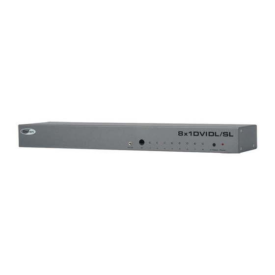
Page 7: Panel Layout
PANEL LAYOUT Front Panel Back Panel... -
Page 8: Panel Descriptions
External IR Port For connection of external IR extension device such as the Gefen IR Extender (part # EXT-RMT-EXTIR). IR Receiver Receives IR signal from the handheld Infrared remote control unit included with the product. DVI Signal Status LEDs 1-8 Provide visual confi... -
Page 9: Connecting And Operating The 8X1 Dvi Dl/Sl Switcher
Switcher’s last recorded EDID from previous activity will be used. How to Operate the 8x1 DVI DL/SL Switcher: Use the RMT-8IR remote control to remotely switch between DVI video sources. Alternatively, use a RS-232 control system such as a PC with communications software (for example, Microsoft’s Hyperterminal... - Page 10 8X1 DVI DL/SL REMOTE DESCRIPTION The RMT-8IR remote control will allow the user to select which of 8 DVI sources will be displayed. Please use the information below when selecting the desired source for output to a display or other DVI video receiving device. RMT-8IR Button DVI Source LED Indicator...
- Page 11 8X1 DVI DL/SL REMOTE INSTALLATION To use the RMT-8IR remote, remove the battery cover on the back of the remote to reveal the battery compartment. Insert the included battery into the open battery slot. The positive (+) side should be facing up. Ensure that both DIP (Dual Inline Package) switches are in the OFF position.
- Page 12 The other DIP switch (8-switch) is reserved for Gefen use only. DIP Switches 1 and 2 on the RMT-8IR directly correspond to DIP Switches 1 and 2 on the 8x1 DVI DL/SL Switcher.
-
Page 13: Edid Notes
There is an bank of 4 DIP switches located on the main circuit board on the underside of the 8x1 DVI DL/SL Switcher. DIP switch 3 can be used to set either the DS or LOCAL EDID modes. The bank of 8 DIP switches are used for the DL (dual link) only feature and are explained on page 12. - Page 14 EDID Modes The diagram below illustrates the DIP switch bank (of 4). The 8 DIP switch bank functions are outlined later on this page. 1 2 3 4 Use DIP switch 3 to set the desired EDID mode. LOCAL EDID Mode (Switch 3=OFF) DEFAULT •...
-
Page 15: Dual-Link-Only Modes
DL (DUAL LINK) ONLY MODES DL (Dual Link) Only Modes The 8 DIP switch bank, located on the underside of the 8x1 DVI DL/SL Switcher cab be used to set each individual input to work in a Dual Link Only mode. These modes should only be enabled if issues occur when using Dual Link sources and displays in the default mode. -
Page 16: Rs-232 Serial Control Interface
The 8x1 DVI DL Switcher can accept commands through the RS-232 serial communications port located on the rear panel. The current RS-232 control features are the ability to switch/route inputs to outputs without the RMT-4IR remote control. How do I use these features? These features were initially intended for utilization by custom installers in automated setups. -
Page 17: Rs-232 Serial Control Commands
RS-232 SERIAL CONTROL COMMANDS RS-232 Features RS-232 remote functions are used to control of this product’s features. Features include input to output routing, EDID storage, EDID management, etc. Functions Syntax The syntax for each function is always the same: #Character as the start fl ag → Function name → Space ( _ ) as function name end fl... - Page 18 RS-232 SERIAL CONTROL COMMANDS #EDIDDSTOLO Function The #EDIDDSTOLO function reads the downstream EDID and stores into all lo- cal inputs. Syntax: #EDIDDSTOLO Parameters: None #EDIDDSTOBA Function The #EDIDDSTOBA function reads the downstream EDID and stores it to a specifi ed EDID bank. Syntax: #EDIDDSTOBA param1 Parameters:...
- Page 19 RS-232 SERIAL CONTROL COMMANDS #DDCTODS Function The #DDCTODS function routes the input DDC to the downstream EDID (pass- through mode). Syntax: #DDCTODS Parameters: None #DDCTOLO Function The #DDCTOLO function routes the input DDC to the local EDID. Syntax: #DDCTOLO Parameters: None #DEF Function The #DEF function set the Switcher to the factory default settings.
- Page 20 RS-232 SERIAL CONTROL COMMANDS #LOEDIDTOBA Function The #LOEDIDTOBA function loads the specifi ed EDID fi le and stores it in a specifi ed EDID bank. Syntax: #LOEDIDTOBA param1 param2 param3 Parameters: param1 param2 param3 Echo mode Value Meaning Semi echo mode Full echo mode EDID size Value...
- Page 21 RS-232 SERIAL CONTROL COMMANDS #LOEDIDTOLO Function The #LOEDIDTOLO function loads the specifi ed EDID fi le to a specifi ed local input. Syntax: #LOEDIDTOLO param1 param2 Parameters: param1 param2 #PRBAEDID Function The #PRBAEDID function reads the EDID fi le from the specifi ed bank and sends it to the serial port.
- Page 22 RS-232 SERIAL CONTROL COMMANDS #PRDSEDID Function The #PRDSEDID function reads the downstream EDID and sends it to the serial port. Syntax: #PRDSEDID param1 Parameters: param1 #PRLOEDID Function The #PRLOEDID function reads the local EDID and spools it to the serial port. Syntax: #PRLOEDID param1 Parameters:...
- Page 23 The commands are not case-sensitive. Command Description Displays the function menu Switch to Input 1 Switch to Input 2 Switch to Input 3 Switch to Input 4 The ASCII character table below indicates which Switcher input will be routed to the output Display when the corresponding ASCII (numeric) character is typed.
- Page 24 2.2 EXAMPLE -- CHANGE THE ROUTED SOURCE Now you are ready to route Display input sources. At the Hyperterminal cursor prompt, type the numeral key of the input to switch to, followed by the ENTER key. Wait until you see the message “Function Done” on the Display. At this point the Display should show the correct Source corresponding to the numeral that was typed.
-
Page 25: Rack Mount Installation
RACK MOUNT INSTALLATION Rack mount ears are provided for installation of this unit into a 1U rack mount space. Locate the side screws on the unit. Remove the front 2 screws that are located closest to the front of the unit. Using the removed screws, screw the rack mounting bracket into the unit. -
Page 26: Specifications
SPECIFICATIONS Video Amplifi er Bandwidth:...165 MHz x 2 Input Video Signal:...1.2 Volts p-p Input DDC Signal:...5 Volts p-p (TTL) Maximum resolutions:...1920 x 1200 (single link), 3840 x 2400 (dual link) DVI Connector:... DVI-I 29-pin female (digital only) RS-232 port: ...DB9 Power Supply:...5V DC Power Consumption:...5 Watts (min.) / 25 Watts (max.) Dimensions:...17.1”W x 1.8”H x 4.2”D... -
Page 27: Specifi Cations
Gefen warrants the equipment it manufactures to be free from defects in material and workmanship. If equipment fails because of such defects and Gefen is notifi ed within two (2) years from the date of shipment, Gefen will, at its option, repair or replace the equipment, provided that the equipment has not been subjected to mechanical, electrical, or other abuse or modifi... - Page 29 Rev A9 20600 Nordhoff St., Chatsworth CA 91311 1-800-545-6900 818-772-9100 fax: 818-772-9120 www.gefen.com support@gefen.com This product uses UL listed power supplies.
Need help?
Do you have a question about the EXT-DVI-841DL and is the answer not in the manual?
Questions and answers