Advertisement
Table of Contents
- 1 Table of Contents
- 2 Operation
- 3 Maintenance
- 4 Exploded Parts Diagram
- 5 Replacement Parts List
- 6 Wiring Diagram
- 7 Heater Assembly Replacement
- 8 Led Light Assembly Replacement
- 9 Fan Assembly Replacement
- 10 Fan Motor and Fan Housing
- 11 Troubleshooting Guide
- Download this manual
See also:
Owner's Manual
IMPORTANT SAFETY INFORMATION: Always read this manual first before attempting to service this log grate. For your
safety, always comply with all warnings and safety instructions contained in this manual to prevent personal injury or prop-
erty damage.
Dimplex North America Limited
1367 Industrial Road Cambridge ON Canada N1R 7G8
1-888-346-7539 www.dimplex.com
In keeping with our policy of continuous product development, we reserve the right to make changes without notice.
© 2013 Dimplex North America Limited
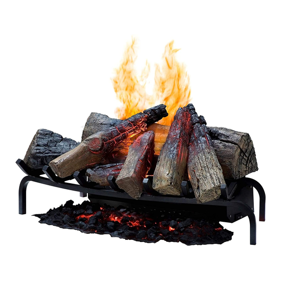
Service Manual
Model
DLGM29
Part Number
6908550000
REV
PCN
DATE
00
-
30-AUG-12
01
-
6-Aug-13
7400620000R01
Advertisement
Table of Contents

Related Manuals for Dimplex DLGM29


Summary of Contents for Dimplex DLGM29
- Page 1 Dimplex North America Limited 1367 Industrial Road Cambridge ON Canada N1R 7G8 30-AUG-12 1-888-346-7539 www.dimplex.com 6-Aug-13 In keeping with our policy of continuous product development, we reserve the right to make changes without notice. © 2013 Dimplex North America Limited 7400620000R01...
-
Page 2: Table Of Contents
NOTE: Procedures and techniques that are considered important enough to emphasize. CAUTION: Procedures and techniques which, if not carefully followed, will result in damage to the equipment. WARNING: Procedures and techniques which, if not carefully followed, will expose the user to the risk of fire, serious injury, or death. www.dimplex.com... -
Page 3: Operation
OPERATION Figure 2 Figure 1 Button Battery Button Battery Cover back on to return to Level 1 - Logs and Light only operation. The manual controls for the Log Grate are located in the Battery Replacement front right side. (Figure 1) A . -
Page 4: Maintenance
NOTE: There are tabs, on each end, that need to be turned to release the components. CAUTION: It is strongly recommended that Distilled water or softened water be used in the unit to prevent scaling of the components. Figure 3 www.dimplex.com... -
Page 5: Exploded Parts Diagram
EXPLODED PARTS DIAGRAM REPLACEMENT PARTS LIST 11. LED Light Assembly ....3001100200RP Power Adapter Set ....2100220100RP 12. -
Page 6: Wiring Diagram
WIRING DIAGRAM 1 2 3 ELEMENT TRANSDUCER 24 VDC MOTOR 7 20 8 21 1 2 3 4 1 2 3 4 LOG #2 LOG #3 LOG #4 LOG #6 LOG #5 LOG #1 EMBERBED www.dimplex.com... -
Page 7: Heater Assembly Replacement
REMOTE CONTROL RECEIVER Figure 4 REPLACEMENT Tools Required: Philips head screwdriver Flat Head Screwdriver WARNING: Disconnect power before attempting any maintenance to reduce the risk of electric shock or damage to persons. NOTE: Ensure that all of the components that contain water have been emptied before performing any maintenance. -
Page 8: Led Light Assembly Replacement
NOTE: Ensure that all of the components that contain water have been emptied before performing any maintenance. 1. Disconnect and remove all of the logs from the unit, including the light shield and associated log, and put Figure 8 Fan Motor Fan Motor www.dimplex.com... -
Page 9: Troubleshooting Guide
TROUBLESHOOTING GUIDE PROBLEM CAUSE SOLUTION General Unit turns on or off by itself Remote control has a similar frequency to Replace Remote Control. Initialize to Remote other remotes in the area. Control Receiver. Defective Remote Control Receiver Replace Remote Control Receiver. Initialize to Remote Control. - Page 10 Mist does not appear to be com- Unit is not level Level unit ing out evenly Log arrangement is blocking air flow Rearrange logs Light Lenses are not correctly oriented Adjust Lenses Light Lenses are not present Replace light lenses www.dimplex.com...
Need help?
Do you have a question about the DLGM29 and is the answer not in the manual?
Questions and answers