Advertisement
This manual covers installation, operation and maintenance. Read carefully before attempting to
install, operate or service the DX‐234 Series Unit Heater.
SAVE THESE INSTRUCTIONS FOR FUTURE REFERENCE
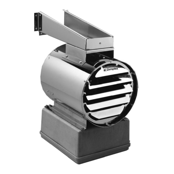
DX‐234 Series
Washdown / Corrosion Resistant
Industrial / Commercial Electric Unit Heater
Owner's Manual
IMPORTANT INSTRUCTIONS
DIMPLEX NORTH AMERICA LTD
1367 INDUSTRIAL ROAD • CAMBRIDGE, ON N3H 4W3
1‐888‐DIMPLEX (1‐888‐346‐7539)
www.dimplex.com • www.dimplex.com/customer_support
7211440100R02
Advertisement
Table of Contents

Related Manuals for Dimplex DX-234 Series


Summary of Contents for Dimplex DX-234 Series
- Page 1 DX‐234 Series Washdown / Corrosion Resistant Industrial / Commercial Electric Unit Heater Owner’s Manual This manual covers installation, operation and maintenance. Read carefully before attempting to install, operate or service the DX‐234 Series Unit Heater. IMPORTANT INSTRUCTIONS SAVE THESE INSTRUCTIONS FOR FUTURE REFERENCE DIMPLEX NORTH AMERICA LTD 1367 INDUSTRIAL ROAD • CAMBRIDGE, ON N3H 4W3 1‐888‐DIMPLEX (1‐888‐346‐7539) www.dimplex.com • www.dimplex.com/customer_support 7211440100R02...
-
Page 2: Important Instructions
IMPORTANT INSTRUCTIONS Installation and maintenance personnel should familiarize themselves with this manual and all the IMPORTANT INSTRUCTIONS before installing or working on this heater to avoid potential unsafe conditions, severe property damage, personal injury or death. 1. Read all instructions before installing and 12. Risk of fire due to high temperatures. Keep operating this heater. electrical cords, drapery, furnishings, 2. Verify that the supply voltage and phase to insulation and other combustibles at least 3 the heater matches the nameplate rating feet (0.9m) from the front of the heater and before energizing. away from the sides, rear and top. 3. Potentially lethal voltages are present. Be 13. Installation minimum mounting clearances sure to lock the branch circuit disconnect specified both on heater nameplate and in switch in the OFF position and tag the this owner’s manual must be maintained. circuit “Out for Maintenance” before 14. Use copper wire rated 90°C min. for supply working on this equipment. connections. 4. Keep electrical enclosure cover tightly 15. This heater should not be used in closed while in operation. potentially explosive atmospheres. Do not 5. Hazard of Electric Shock. Heater must be use in areas where gasoline, paint, or grounded in accordance with both local and ... -
Page 3: Installation Instructions
INSTALLATION INSTRUCTIONS RISK OF FIRE / EXPLOSION This heater should not be used in potentially explosive atmospheres. Do not use in areas where gasoline, paint or flammable liquids are used or stored. Keep electrical cords, drapery, furnishings, insulation and other combustibles at least 3 feet (0.9m) from the front of the heater and away from the sides, rear and top. Installation minimum clearances specified both on the heater nameplate and in the owner’s manual must be maintained. Do not use as a residential or household heater. These air heaters are designed for comfort heating and Large room with exposed walls and roof : should not be used in ambient temperatures exceeding 80ºF (26.7ºC). They are to be permanently mounted to the FIGURE 1 wall or ceiling for horizontal discharge. The unit is designed to give years of safe, trouble‐free operation when properly installed and maintained. A. Site Selection: The heaters are intended for elevated mounting locations so that they blow warm air down to the floor area. A mounting height should be selected so that the heater is out of the way of possible moving equipment or personnel, yet low enough to deliver warm air to the selected area. See the mechanical installation section for ... - Page 4 INSTALLATION INSTRUCTIONS – Continued B. Mechanical Installation: Once an acceptable location has been determined, see the These heaters are to be mounted for horizontal discharge following instructions to complete the mechanical only. Mounting is to be accomplished by using either (4) installation: 3/8x16 threaded rods (supplied by others) or the stainless 1. To ensure proper heating of floor surfaces, observe steel swivel mounting bracket factory supplied with the the following recommended mounting height heater. Lock washers should be used on all mounting nuts limitations (to bottom of heater): and bolts to ensure they don’t vibrate or work loose due to fan vibration or other vibration transmitted to the TABLE 3: Max. Mounting Height from Floor, feet (m) heater. <= 5 KW 5.1 to 10 10.1 to 20 20.1 to 47 KW KW KW The supporting structure that the heater is attached to 10’ (3m) 15’ (4.6m) 20’ (6.1m) 25‘ (7.6m) must have adequate strength to safely support the heater. The heater dimensions and maximum unit weights are: 2. Install the heater at least 6 feet (1.8m) from the floor and 8” (203mm) from the wall or ceiling. TABLE 1: ...
- Page 5 INSTALLATION INSTRUCTIONS – Continued Ceiling or wall mount using swivel bracket (cont): Optional Ceiling Installation using 4 threaded rods: For ceiling installation using threaded rods, secure the four rods to the ceiling using locknuts. TABLE 4: KW BH BL M 4.25” 19.50” 8.50” <= 12 (108mm) (495mm) (216mm) 7.125” 22.25” 3.25” 12.1 to 47 (181mm) (565mm) (83mm) ...
-
Page 6: Electric Shock Hazard
INSTALLATION INSTRUCTIONS ‐ Continued ELECTRIC SHOCK HAZARD Electrical installation should be made by a qualified licensed electrician. Wiring procedures, connections and grounding shall be in accordance with the national and local codes having jurisdiction. C. Electrical Installation: Follow these instructions to complete the electrical installation: 1. External branch circuit protection is required. See nameplate ratings and follow Code recommendations. 2. Follow the national and local electrical and building codes related to the installation and intended use of the heater. 3. When doing any work on a heater, including the initial electrical connection, disconnect the electrical supply at the main branch circuit switch, and lock the switch in the off (open) position. Tag the circuit "Out for Maintenance" to prevent potential lethal shock hazards. 4. Confirm that the electrical power supply matches the nameplate voltage, phase, amperage and frequency rating of the heater to be connected. 5. Field supply conductors must be sized for at least 125% of the circuit current. The circuit current in amps is calculated as follows: Single Phase Amperage = Circuit kW x 1000 Circuit Voltage Three Phase Amperage = Circuit kW x 1000 1.732 x Circuit Voltage 6. Use copper conductors rated 90°C minimum with watertight conduit fittings. 7. ... - Page 7 OPERATING INSTRUCTIONS RISK OF FIRE / EXPLOSION This heater should not be used in potentially explosive atmospheres. Do not use in areas where gasoline, paint or flammable liquids are used or stored. Keep electrical cords, drapery, furnishings, insulation and other combustibles at least 3 feet (0.9m) from the front of the heater and away from the sides, rear and top. To prevent a possible fire, do not block or allow foreign objects to enter air intakes or exhaust in any manner. ELECTRIC SHOCK HAZARD Keep electrical enclosure cover tightly closed while in operation. Do not operate heater after a malfunction. Disconnect power at service panel and have heater inspected by a reputable electrician before reusing. Use this heater only as described in this manual. Any other use is not recommended by the manufacturer and may result in fire, electric shock or personal injury. RISK OF INJURY / BURN The heater and discharge air are hot when in use. To avoid burns, do not let bare skin touch hot surfaces. Do not attempt to service or clean heater while unit is operating as there is a hazard from electric shock, injury from operating fan blade and burns from hot heating elements. The unit is designed to give years of safe, trouble‐free operation when properly installed and maintained. Please read the following guidelines to ensure reliable operation: 1. Confirm proper mechanical and electrical installation before operation of the heater. 2.
- Page 8 OPERATING INSTRUCTIONS ‐ Continued RISK OF FIRE / EXPLOSION This heater should not be used in potentially explosive atmospheres. Do not use in areas where gasoline, paint or flammable liquids are used or stored. Keep electrical cords, drapery, furnishings, insulation and other combustibles at least 3 feet (0.9m) from the front of the heater and away from the sides, rear and top. To prevent a possible fire, do not block or allow foreign objects to enter air intakes or exhaust in any manner. ELECTRIC SHOCK HAZARD Keep electrical enclosure cover tightly closed while in operation. Do not operate heater after a malfunction. Disconnect power at service panel and have heater inspected by a reputable electrician before reusing. Use this heater only as described in this manual. Any other use is not recommended by the manufacturer and may result in fire, electric shock or personal injury. RISK OF INJURY / BURN The heater and discharge air are hot when in use. To avoid burns, do not let bare skin touch hot surfaces. Do not attempt to service or clean heater while unit is operating as there is a hazard from electric shock, injury from operating fan blade and burns from hot heating elements. The unit is designed to give years of safe, trouble‐free operation when properly installed and maintained. Please read the following guidelines to ensure reliable operation: 10.
-
Page 9: Maintenance Instructions
MAINTENANCE INSTRUCTIONS ELECTRIC SHOCK HAZARD Potentially lethal voltages are present. Be sure to lock the branch circuit disconnect switch in the OFF position and tag the circuit “Out for Maintenance” before working on this equipment. RISK OF INJURY / BURN Do not attempt to service or clean heater while unit is operating as there is a hazard from electric shock, injury from operating fan blade and burns from hot heating elements. Maintenance and repair must be performed by qualified service personnel only. Electrical: Mechanical: . Inspect all terminal connections, contactors and 1. Before cleaning or servicing, ensure power has been conductor insulation for damage, looseness, fraying, turned off at the service panel and the heating etc., as applicable. Tighten any loose terminals and elements are cool. replace or repair wire that has damaged or 2. Annually check the tightness of all visible bolts and deteriorated insulation. Replace any contactor that nuts, in particular the support structure bolts and has contacts that are badly pitted, welded together, nuts. or burned. 3. Periodically, check the motor, fan, discharge 2. If reduced heat output is suspected, perform the openings, intake openings, heating elements and mechanical checks. If low heat output is still suspected control compartment for cleanliness. If necessary, after completing the mechanical checks, verify the clean by using a vacuum or compressed air. Be careful condition of the heating elements by visual inspection not to bend or distort the fan blade propeller. and by using an amperage meter to check the current ...
Need help?
Do you have a question about the DX-234 Series and is the answer not in the manual?
Questions and answers