Table of Contents
Advertisement
Advertisement
Table of Contents

Subscribe to Our Youtube Channel
Related Manuals for BC Biomedical DPM-2001


Summary of Contents for BC Biomedical DPM-2001
- Page 1 DIGITAL PRESSURE METERS DPM-2001 DPM-2001PLUS DPM-2100 USER MANUAL...
-
Page 2: Table Of Contents
DPM-2100 ......................10 SETUP MODE ......................12 INPUTS ........................13 STATUS DISPLAYS..................... 14 COMMUNICATIONS....................15 MANUAL REVISIONS....................20 WARRANTY......................... 20 SPECIFICATIONS ....................... 21 DRAWINGS DPM-2001 PHYSICAL DIAGRAM..............23 DPM-2001 PLUS PHYSICAL DIAGRAM ............24 DPM-2100 PHYSICAL DIAGRAM..............25 NOTES......................... 26... - Page 3 PERFORMANCE AND TO SUPPLY THE BEST POSSIBLE PRODUCT. THE INFORMATION IN THIS MANUAL HAS BEEN CAREFULLY CHECKED AND IS BELIEVED TO BE ACCURATE. HOWEVER, NO RESPONSIBILITY IS ASSUMED FOR INACCURACIES. Manual DPM-2001, 2001 PLUS, 2100 Copyright © 2004 www.bcgroupintl.com MADE IN THE USA...
-
Page 4: Description
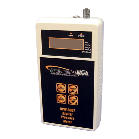
DPM-2001/2001 PLUS/2100 DIGITAL PRESSURE METERS The Model DPM-2001 Series is a Microprocessor based Digital Pressure Meter family. They measure both gas and liquid pressures and provide multiple engineering unit displays for the results. The DPM-2100 Series adds temperature measurement. The following are highlights of some of the main features. - Page 5 OPTIONAL ACCESSORIES: • BE2000PU 120 VAC BATTERY ELIMINATOR, U.S. • BE2000PE 220 VAC BATTERY ELIMINATOR, EUROPE • DPM2000C RS-232 CABLE • BC20-01004 HARD CARRYING CASE • BC20-01005 UNIVERSAL PRESSURE ADAPTER KIT...
-
Page 6: System Indicators
SYSTEM INDICATORS Four indicators are provided to identify the Current Operating Mode. PRESSURE SCALE – The pressure scale is indicated by an identifier bar. The RANGE key will toggle the pressure units among PSI, mmHG, inH O and cmH O. The following is a breakdown of the available pressure scales and the measurement range for each scale: Identifier Bar Pressure Units... -
Page 7: Dpm-2001
KEYS – DPM-2001 Four tactile-touch keys are provided for system operation. ON/SETUP – The function of this key is dependant on the Current Operating Mode as follows: POWER OFF – If this key is pressed while the power is turned OFF, the power will be turned ON PRESSURE MEASUREMENT –... - Page 8 RANGE/UP – The function of this key is dependant on the Current Operating Mode as follows: PRESSURE MEASUREMENT – If this key is pressed while the pressure is being displayed, the unit will step through the available pressure ranges (PSI, 0, cmH 0 and mmHg).
-
Page 9: Dpm-2001 Plus
KEYS – DPM-2001 PLUS Six tactile-touch keys are provided for system operation. ON/SETUP – The function of this key is dependant on the Current Operating Mode as follows: POWER OFF – If this key is pressed while the power is turned OFF, the power will be turned ON PRESSURE MEASUREMENT –... - Page 10 MAX/UP – The function of this key is dependant on the Current Operating Mode as follows: PRESSURE MEASUREMENT – If this key is pressed while the pressure is being displayed, the unit will display the maximum pressure detected since the capture register was last reset.
-
Page 11: Dpm-2100
KEYS – DPM-2100 Six tactile-touch keys are provided for system operation. ON/SETUP – The function of this key is dependant on the Current Operating Mode as follows: POWER OFF – If this key is pressed while the power is turned OFF, the power will be turned ON PRESSURE MEASUREMENT –... - Page 12 MAX/UP – The function of this key is dependant on the Current Operating Mode as follows: PRESSURE MEASUREMENT – If this key is pressed while the pressure is being displayed, the unit will display the maximum pressure detected since the capture register was last reset.
-
Page 13: Setup Mode
SETUP MODE The Setup Mode allows the user to adjust the configuration of the meter. The Setup Mode is entered by pressing The ON/SETUP key when the unit is on. The parameter and the current value will alternately flash in the display. The following table indicates the Parameters that are available, their meaning and available setting range: PARAMETER DESCRIPTION... -
Page 14: Inputs
INPUTS PRESSURE INPUT – Male luer lock connector is used for the pressure input. POWER INPUT – A 2.1 mm jack is provided for the optional 9 VDC Battery Eliminator power supply that may be used for continuous run applications. It bypasses the internal battery when plugged in. -
Page 15: Status Displays
STATUS DISPLAYS LOW BAT – This status screen displays when the battery reaches a critical low level. LOW BAT is displayed for two seconds once a minute until the battery is replaced. DEF CAL – This status screen displays on Power Up if the unit is out of Calibration. The unit will load default values. -
Page 16: Communications
NOTE: RS232 is only available on DPM-2001 Plus and DPM-2100 models. Use RS232 Cable P/N DPM2000C to connect from the RS232 connector on the top of the DPM to a DB9 Com Port connector on a PC. - Page 17 READ/WRITE COMMANDS The READ command is utilized to read from the meter any of the gathered data. The command is entered as a letter followed by 2 numbers, followed by a carriage return: R(Location)(Return) The 'R' indicates to the meter that the command is to be a READ command. The Location contains two digits that indicate the data location that is to be read.
- Page 18 0-65535 RESERVED 0-65535 RESERVED 0-65535 RESERVED 0-65535 FILTER CONSTANT 0-255 RESERVED 0-65535 0 = DPM-2001 MODEL 1 = DPM-2001+ 2 = DPM-2100 PRESSURE See Note 1 MAX PRESSURE See Note 1 MIN PRESSURE See Note 1 TEMPERATURE See Note 1...
- Page 19 UPLOAD COMMAND The Upload command allows the user to read all of the selected device data from locations 1 through 18 with a single command. The data will be transmitted as a single block with each location separated by a carriage return, linefeed ($0D,$0A). The following is the format for this command: U (Return) See the table in the Read Command section for details on the data structure.
- Page 20 VERSION COMMAND The Version command allows the user to read the Software Version that the unit is running. To read the Version, the following syntax is used: V (RETURN) CANCEL COMMAND The CANCEL command is simply a way to re-establish proper control, should an error occur or an incorrect command be transmitted.
-
Page 21: Manual Revisions
MANUAL REVISIONS Revision # Program # Revisions Made Rev 01 DT7325CA Preliminary Manual Rev 02 DT7325CA Editing/Drawing Updates Rev 03 DT7325CA Battery Eliminator Rev 04 DT7325CB Status Displays Rev 05 DT7325CD Accuracy Upgrades Rev 06 DT7325CG Program Upgrades, Color Overlays LIMITED WARRANTY : BC GROUP INTERNATIONAL, INC. -
Page 22: Specifications
SPECIFICATIONS DPM-2001/DPM-2001 PLUS/DPM-2100 DIGITAL PRESSURE METERS PRESSURE RANGE -13.50 to 100.00 PSI -701 to 5190 mmHg @ 20C -374 to 2773 inH O @ 20C -951 to 7043 cmH O @ 20C PRESSURE RESOLUTION 0.01 PSI 1 inH 1 cmH... - Page 23 SIZE 7.09 x 3.94 x 1.56 inches 180 x 100 x 40 mm (HxWxD) WEIGHT < 1 lbs. (0.45 kg) CONNECTIONS Power – 2.1mm Center Negative RS-232 – 1/8 inch phono Pressure – Male Luer Temperature – 1/4 inch phono TEMPERATURE SENSOR Directly compatible with all YSI Series 700 Temperature Probes...
-
Page 27: Notes
NOTES...
Need help?
Do you have a question about the DPM-2001 and is the answer not in the manual?
Questions and answers