Table of Contents
Advertisement
Advertisement
Table of Contents

Related Manuals for BC Biomedical ESU-2400


Summary of Contents for BC Biomedical ESU-2400
- Page 1 ELECTROSURGICAL UNIT ANALYZER ESU-2400 Series USER MANUAL...
-
Page 3: Table Of Contents
BC BIOMEDICAL ESU-2400 SERIES TABLE OF CONTENTS WARNINGS, CAUTIONS, NOTICES ................iii DESCRIPTION ......................Accessories ......................3 OVERVIEW ........................7 TYPICAL MEASUREMENT CONNECTIONS ..............8 Monopolar ......................... 8 Bipolar ........................9 External Loads ......................10 Tissue Response Test ..................... 12 Leakage Mode 1a .................... - Page 4 Load Curves Scenario 1: Bipolar, 60W, 100 to 1000 ohms, auto trigger DUT ......41 Scenario 2: Pure Cut, 300W, Load List, manual trigger DUT ........ 44 Autosequence RF Measure: 200 ohms, 315mA Limit, ±10mA ............47 Load Curve: Pure Cut, 300W, 50-5000 ohms, Manual Trigger ......50 Auto CQM ......................
- Page 5 LIMITED WARRANTY ....................164 SPECIFICATIONS ..................... 166 NOTES ........................174 CALIBRATION INTERVAL To ensure the accuracy of the ESU-2400 Series Analyzers, BC Group International, Inc. recommends that it be calibrated at least once every 12 months. Calibration must be done by qualified personnel.
- Page 6 The ESU-2400 Series is for use by skilled technical personnel only. WARNING - USE The ESU-2400 Series is intended for testing only and should never be used in diagnostics, treatment or any other capacity where it would come in contact with a patient.
- Page 7 WARNING - LIQUIDS Do not submerge or spill liquids on the ESU-2400 Series. Do not operate the ESU-2400 Series if internal components not intended for use with fluids may have been exposed to fluid, as the internal leakage may have caused...
- Page 8 CAUTION - SERVICE The ESU-2400 Series is intended to be serviced only by authorized service personnel. Troubleshooting and service procedures should only be performed by qualified technical personnel. CAUTION - ENVIRONMENT Exposure to environmental conditions outside the specifications can adversely affect the performance of the ESU-2400 Series.
- Page 10 NOTICE – SYMBOLS Symbol Description Caution (Consult Manual for Further Information Per European Council Directive 2002/95/EC, do not dispose of this product as unsorted municipal waste. NOTICE – ABBREVIATIONS AAMI Association for the Advancement of Medical Instrumentation Amps Amperes ANSI American National Standards Institute ARM™...
- Page 11 NOTICE – PERFORMING TESTS REFER TO DUT MANUFACTURER’S SERVICE MANUAL FOR TEST PROCEDURES AND MEASUREMENT LIMITS NOTICE – DISCLAIMER USER ASSUMES FULL RESPONSIBILITY FOR UNAUTHORIZED EQUIPMENT MODIFICATIONS OR APPLICATION OF EQUIPMENT OUTSIDE PUBLISHED INTENDED SPECIFICATIONS. SUCH MODIFICATIONS OR APPLICATIONS MAY RESULT IN EQUIPMENT DAMAGE OR PERSONAL INJURY. NOTICE –...
- Page 12 NOTICE – CONTACT INFORMATION BC BIOMEDICAL BC GROUP INTERNATIONAL, INC. 3081 ELM POINT INDUSTRIAL DRIVE ST. CHARLES, MO 63301 1-800-242-8428 1-314-638-3800 www.bcgroupintl.com sales@bcgroupintl.com esu.bcgroupintl.com ESU-2400 Series User Manual Copyright © 2017 www.bcgroupintl.com Made in the USA 11/17 Rev 10...
-
Page 13: Description
ELECTROSURGICAL UNIT ANALYZER This manual covers the model ESU-2400 and ESU-2400H Electrosurgical Unit Analyzers. Throughout this manual the term ESU-2400 will be used to apply to both models. Sections that are specific to the ESU-2400H model will use the term ESU-2400H exclusively. - Page 14 The following are highlights of some of the main features: • TRUE RMS READINGS USING DFA ® TECHNOLOGY • INDUSTRY STANDARD CURRENT SENSING TECHNOLOGY • mV, mV PEAK, mA, CREST FACTOR AND POWER (WATTS) RANGES, LOAD VOLTAGE(ESU-2400H only) • COLOR QVGA DISPLAY WITH TOUCHSCREEN •...
-
Page 15: Accessories
STANDARD ACCESSORIES: BC20 – 00130 Accessory Kit (Test Leads) BC20 – 21107 Universal Power Supply BC20 – 41341 Communications Cable (RS-232) BC20 – 205XX Standard Power Adapter (International Options, See Page 138 For Details) Standard Accessory Kit, BC20-00130: RECQM Lead Active Lead Lead... - Page 16 BC20 – 03005 Monopolar Hand Switch Simulator BC20 – 03006 Footswitch Cable for Olympus ESG-100 BC20 – 03007 Footswitch Cable for Olympus ESG-400 TRL – 2420 Tissue Response Load...
- Page 17 OPTIONAL ACCESSORIES (continued): Optional Accessory Kit, BC20-00131, ForceTriad PM Accessory Kit Carrying Case External Cross Coupling Load UFP Port Adapter Autobipolar Lead Cross Coupling Lead Cross Coupling Lead TRL-2420 BC20-03004 Tissue Response Load Footswitch Simulator BC20-03005 Monopolar Handpiece Simulator...
- Page 18 Note that some generators do not allow for the REM circuit to be disabled. For these generators it does not matter which cable is used. When using the ESU-2400 CQM test mode, the cable with the pin must be used. For other modes, the Dispersive ports on the ESU-2400 are shorted together and the cable without the pin should be used.
-
Page 19: Overview
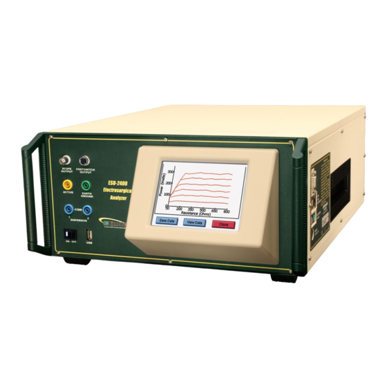
OVERVIEW This section looks at the layout of the ESU-2400 and gives descriptions of the elements that are present. Oscilloscope Footswitch Interface Durable Powder-Coated, Output Automated DUT Custom Aluminum Case Activation Safety Jacks Swivel RF Input Carrying Handle Computer Interface... -
Page 20: Typical Measurement Connections
TYPICAL MEASUREMENT CONNECTIONS The ESU-2400 Series utilizes an internal current transformer and internal precision load resistors for simple configuration of typical Electrosurgical Generator testing. Many of the world’s leading Electrosurgical generator manufacturers utilize this exact same technique when they test, service and calibrate their generators. -
Page 21: Bipolar
Bipolar: 1. Yellow Active Lead from Active Jack on ESU-2400 to DUT Bipolar Output Electrode #1. 2. Blue Lead from Dispersive1 Jack on ESU-2400 to DUT Bipolar Output Electrode #2. ESU (DUT) Bipolar Electrode #1 ESU (DUT) Bipolar Electrode #2... -
Page 22: External Loads
External Loads Monopolar: 1. Yellow Active Lead from Active Jack on ESU-2400 to DUT Output. 3. Blue Lead from Dispersive 1 Jack on ESU-2400 to External Load. 4. External Load to DUT Dispersive. ESU (DUT) Active Electrode ESU (DUT) Patient Return/... - Page 23 Bipolar 1. Yellow Active Lead from Active Jack on ESU-2400 to DUT Bipolar Output Electrode #1. 2. Blue Lead from Dispersive 1 Jack on ESU-2400 to External Load. 3. External Load to DUT Bipolar Output Electrode #2. ESU (DUT) Bipolar...
-
Page 24: Tissue Response Test
Return Active If the output terminals of the DUT are not compatible with the standard ESU-2400 safety test leads, the alligator clips supplied with the ESU-2400 accessory kit can be used to connect directly to the electrosurgical instrument as shown in the connection diagram... -
Page 25: Leakage Mode 1A
19.101b, fig, 104 and sec. 19.102, adopted by ANSI/AAMI HF18-2001. The purpose of this test is to verify that open circuit RF leakage of the DUT meets or exceeds the IEC specification. The ESU-2400 internally connects the load to earth ground. An external ground is also provided at the front panel. -
Page 26: Leakage Mode 1B
WARNING – ONE LEAD AT A TIME Only test one lead of the ESU Generator at a time, either Active or Dispersive, not both. Connections 1. Dispersive 1 Jack on ESU-2400 to DUT Dispersive Output or Bipolar 2. Earth Ground to DUT equipotential jack... -
Page 27: Leakage Mode 2
ANSI/AAMI HF18-2001. The purpose of this test is to verify that the RF leakage of the DUT meets or exceeds the IEC specification. Connections 1. Active Lead from Active Jack on ESU-2400 to DUT Active Output. 2. Dispersive Lead from Dispersive Jack on ESU-2400 to DUT Dispersive. ESU (DUT) -
Page 28: Leakage Mode 3
ANSI/AAMI HF18-2001. The purpose of this test is to verify that the RF leakage of the DUT meets or exceeds the IEC specification. Connections 1. Active Lead from Active Jack on ESU-2400 to DUT Active Output. 2. Dispersive Lead from Dispersive Jack on ESU-2400 to DUT Dispersive. ESU (DUT) -
Page 29: Getting Started
GETTING STARTED This section was written to help you get started with the ESU-2400. Examples are given for typical configurations of RF Measurement, REM/ARM/CQM testing, Load Curves and Autosequences. This section will give specific examples of how to configure the ESU-2400 plus additional modifications that might help fulfill your specific testing requirements. -
Page 30: Measure Rf Energy
Solution – 1. Select Measure RF Energy from the main menu. 2. Connect the Active output from the DUT to the Active input on the ESU-2400. If you are using the cables from the ESU-2400 accessory kit, use the Yellow Lead. - Page 31 5. Press the Test Load button to open the load configuration box. The screen should look like the following: NOTE: The ESU-2400 can be configured to use internal loads, external loads, or a combination of both. First select the Load Mode, then enter the desired internal and external loads. The total load will automatically be updated.
-
Page 32: Scenario 2: Measure Ma And Watts, 300 Ohm Load, Footswitch Triggers Dut
Solution – 1. Select Measure RF Energy from the main menu. 2. Connect one Bipolar output from the DUT to the Active input on the ESU-2400. If you are using the cables from the ESU-2400 accessory kit, use the Yellow Lead. - Page 33 6. Press the Display Parameters button and select Two Readings from the Select Screen menu. NOTE: By default mA RMS and Watts RMS are shown when Two Readings are selected. Each position can display any of the ESU-2400 measurements by pressing the corresponding measurement button.
- Page 34 BC20-03000, the output selection is dependent on how the cable is wired. 10. Press the footswitch button to trigger the DUT. The mA and Watts measurements will be shown on the ESU-2400 Screen. 11. You may either wait for the Footswitch Activation Timeout, or press the...
-
Page 35: Scenario 3: Measure Hyfrecator Ma, 200 Ohm Load, Manual Dut Trigger
Solution – 1. Select Measure RF Energy from the main menu. 2. Connect the Active output from the DUT to the Active input on the ESU-2400. If you are using the cables from the ESU-2400 accessory kit, use the Yellow Lead. - Page 36 4. Press the Test Load button to open the load configuration box. The screen should look like the following: NOTE: The ESU-2400 can be configured to use internal loads, external loads, or a combination of both. First select the Load Mode, then enter the desired internal and external loads. The total load will automatically be updated.
-
Page 37: Scenario 4: Measure Ma And Khz, 200 Ohm Load, Manual Dut, Pulse Mode 1
Solution – 1. Select Measure RF Energy from the main menu. 2. Connect the Active output from the DUT to the Active input on the ESU-2400. If you are using the cables from the ESU-2400 accessory kit, use the Yellow Lead. - Page 38 6. This will open the Pulsed Mode Configuration screen. Select Pulsed Mode 1 by clicking on the mode button or the picture. 7. A threshold should be chosen so that the pulse will be over the threshold but not too close to the maximum value to account for variations in the waveform. In this scenario 600mA is sufficient to detect the 700mA waveform.
- Page 39 11. By default mA and Watts are displayed when selecting two readings. Press the button labeled Watts and then press the button labeled kHz to change the measurement to frequency. 12. Trigger the DUT. The measurements will be displayed on the ESU-2400.
-
Page 40: Scenario 5: Measure V, Delayed Mode
Solution – 1. Select Measure RF Energy from the main menu. 2. Connect the Active output from the DUT to the Active input on the ESU-2400. If you are using the cables from the ESU-2400 accessory kit, use the Yellow Lead. - Page 41 6. This will open the Delayed Mode Configuration screen. Press the button below “Delay Time” and enter 2000 ms as the delay. 7. Click the Accept Changes button to enter your settings and return to the measurement screen.
- Page 42 8. By default mA is displayed. Press the button labeled mA and then press the button labeled V Load to change the measurement to load voltage. 9. Trigger the DUT. The measurements will be displayed on the ESU-2400H.
-
Page 43: Measure Rf Leakage
ESU-2400 accessory kit, use the Yellow Lead. 4. Connect earth ground port on the ESU-2400 to the ground lug on the back of the DUT. If you are using the cables from the ESU-2400 accessory kit, use the green cable and green alligator clip. - Page 44 5. Trigger the DUT. The ESU-2400 will show the mA RMS measurement in the display.
-
Page 45: Leakage Test 1B: Dispersive To Ground
ESU-2400. If you are using the cables from the ESU-2400 accessory kit, use the Blue cable without the clear pin. 4. Connect earth ground port on the ESU-2400 to the ground lug on the back of the DUT. If you are using the cables from the ESU-2400 accessory kit, use the green cable and green alligator clip. - Page 46 5. Trigger the DUT. The ESU-2400 will show the mA RMS measurement in the display.
-
Page 47: Leakage Test 2: Ground Referenced Dut, Active To Ground
ESU-2400. If you are using the cables from the ESU-2400 accessory kit, use the Blue cable without the clear pin. 5. Connect earth ground port on the ESU-2400 to the ground lug on the back of the DUT. If you are using the cables from the ESU-2400 accessory kit, use the green cable and green alligator clip. - Page 48 6. Trigger the DUT. The ESU-2400 will show the mA RMS measurement in the display.
-
Page 49: Leakage Test 3: Ground Referenced Dut, Dispersive To Ground
ESU-2400. If you are using the cables from the ESU-2400 accessory kit, use the Blue cable without the clear pin. 5. Connect earth ground port on the ESU-2400 to the ground lug on the back of the DUT. If you are using the cables from the ESU-2400 accessory kit, use the green cable and green alligator clip. - Page 50 6. Trigger the DUT. The ESU-2400 will show the mA RMS measurement in the display.
-
Page 51: Rem/Arm/Cqm Test
3. Connect the Dispersive output from the DUT to the Dispersive inputs on the ESU-2400. If you are using the cables from the ESU-2400 accessory kit, use the Blue cable with the center pin. 4. The DUT REM state should be Normal. -
Page 52: Scenario 2: Increase Rem By 40
4. Connect the Dispersive output from the DUT to the Dispersive inputs on the ESU-2400. If you are using the cables from the ESU-2400 accessory kit, use the Blue cable with the center pin. -
Page 53: Load Curves
Load Curve Scenario 1 – I need to run a bipolar load curve at 60 Watts with loads from 100 to 1000 ohms, measuring every 100 ohms. I am testing a ForceFx generator and want the ESU-2400 to automatically configure and trigger the DUT. Solution –... - Page 54 10. Press the DUT tab at the top of the screen to configure the settings for the DUT trigger. 11. Select the ESU-2400 option for DUT activation. This will enable features for configuring the DUT setup. The screen should look like the following: 12.
- Page 55 14. Use the dropdown arrow to set the DUT mode to the desired bipolar output mode. The screen should now look like the following: 15. Connect the ESU-2400 to the DUT. Connect the Yellow cable from the Active port on the ESU-2400 to one of the Bipolar outputs on the DUT. Connect the Green cable from the Dispersive 1 port of the ESU-2400 to the other Bipolar output on the DUT.
-
Page 56: Scenario 2: Pure Cut, 300W, Load List, Manual Trigger Dut
Load Curve Scenario 2 – I need to run a pure cut 300 Watt load curve, but there isn’t a footswitch cable available for my DUT. I need to test my DUT at 50, 300, 500, 800, and 1500 ohms. Solution –... - Page 57 8. Press the Setup Power tab at the top of the screen to configure the power setting for the test. 9. Select the Single Power Level tab to configure the test for one power setting. 10. Press the DUT Power setting button and enter 300 in the number pad. The screen should look like the following: 11.
- Page 58 13. Connect the ESU-2400 to the DUT. Connect the Yellow cable from the Active port on the ESU-2400 to active output on the DUT. Connect the Blue cable from the Dispersive ports of the ESU-2400 to the return on the DUT.
-
Page 59: Rf Measure: 200 Ohms, 315Ma Limit, ±10Ma
AUTOSEQUENCES RF Measure: I need to configure an Autosequence step to take an RF current measurement with a 200 ohm load. My measurement tolerance is 315mA, ±25mA. Solution – 1. From the Autosequence menu, select Create New Sequence. Then press Add Step. - Page 60 Additionally, if the desired reading were watts or any other measurement taken by the ESU-2400, the red button to the right of the expected reading can be pressed to change the measurement being tested. 14. Press the number button for High Limit and set the value to 25 with the number pad.
- Page 61 16. Additionally, if you would like to allow the user to override the automated limit testing, you can check the box next to Allow operator to select Pass/Fail status. 17. The screen should look like the following; the configuration is complete for this step.
-
Page 62: Load Curve: Pure Cut, 300W, 50-5000 Ohms, Manual Trigger
Load Curve– I need to run a pure cut 300 Watt load curve, and there isn’t a footswitch cable available for my DUT. I need to take 10 measurements with loads from 50 to 5000 ohms. Solution – 1. From the Autosequence menu, select Add Step. 2. - Page 63 8. Press the Load resistance setting for the First Load and enter 50 in the number pad. 9. Press the Load resistance setting for the Last Load and enter 5000 in the number pad. 10. Press the step setting in the Total Steps in Test option and enter 10 in the number pad.
-
Page 64: Auto Cqm
Auto CQM– I need to test the CQM input on my generator. My generator service manual says to increase the CQM resistance starting at 120 ohms until the CQM alarm occurs. The CQM trip resistance should be 135 ohms +/- 5 ohms. Solution –... - Page 65 8. Select the Step Values tab to configure the CQM resistance to be used. The screen should look like the following: 9. Press the First Load button and enter 120 in the number pad. 10. Press the Last Load button and enter 145 ohms. 11.
-
Page 66: Main Screen
MAIN SCREEN The ESU-2400 boots to the main screen by default. The power up screen can be changed in the System Setup screen. The main screen provides a quick way to select the desired operating mode. Autosequences This mode provides for automated DUT testing. Autosequences can consist of any combination of user instructions, RF measurements, Load Curves, or CQM tests. - Page 67 All switching for the leakage modes is performed by internal relays. System Tools This mode provides for configuration of the ESU-2400. In this mode the user can calibrate the touchscreen, update the system firmware, and adjust settings such as filter rate and system volume.
- Page 68 System Information The system information screen is shown by pressing the ESU-2400 title bar on the main screen. This window provides the basic information about the system including software versions and calibration due date. To exit the system information screen, simply press anywhere on the screen.
-
Page 69: Autosequences
AUTOSEQUENCES The autosequence is a programmable procedure for performing testing on a generator. The autosequence can consist of any combination of user instructions, RF measurements, Load Curves, or CQM tests. Once an autosequence is created, it can be saved as a secure sequence, which cannot be modified. The following image shows the main autosequence menu, where the user can load an autosequence, begin a ForceTriad PM, view previously saved test results, or create new autosequence. - Page 70 The following screen is shown after opening an autosequence setup file. When a step is selected, it is highlighted in blue and expanded to show the step details. When a step is not selected, the background is white and only the essential details of the step are shown.
- Page 71 Add Step – This button will show the add step dialog box, shown below. To add a step to the autosequence, select where to add the step and then press OK. Delete Step – This button will delete the selected step from the autosequence. Copy Step –...
- Page 72 Edit Step – This button will show the edit step window, shown below. Each step has a field for the step title and instructions to the user. These fields must be entered using an external keyboard or remotely with a PC. Each step can be configured as an Instruction Only, RF Energy / Leakage, Load Curve, or REM/ARM/CQM step by selecting the appropriate option button at the bottom of the step edit screen.
- Page 73 For RF Energy / Leakage and Load Curve steps, the user needs to configure how the DUT will be activated. For these measurements, the DUT can be activated by the Operator or the ESU-2400 as shown below. When Operator is selected, the user will be prompted when to activate or deactivate the ESU.
- Page 74 300 watts. When the DUT Setup is set to Setup by Model, the user selects the DUT manufacturer and model as well as the desired output mode. The ESU-2400 handles all of the RS-232 and footswitch output setup.
- Page 75 RF Energy / Leakage step configuration. The user must configure both the ESU-2400 meter as well as the measurement tolerance. To setup the tolerance, select the Tolerance option button at the bottom of the screen.
- Page 76 DUT Power Setting – This setting represents what the DUT should be set to for the current step. Expected Reading – This sets how the ESU-2400 determines whether a measurement passes or fails. Available settings are Equal To (%), Less Than, Greater Than, or Equal To (Value).
- Page 77 For the step based loads, the user enters the first load to be used and the last load to be used. Then the ESU-2400 steps the loads by either a fixed resistance or by a calculated amount to achieve a fixed number of steps for the test. In the previous picture, the load curve would start at 50 ohms, and increment the load by 35 ...
- Page 78 For list based loads, the following screen is shown, allowing the user to select specific resistances to be used for the test. The load configuration list can be saved to a file or loaded from a previously saved list. The loads are automatically sorted by value as they are added to the list.
- Page 79 Single Power Level Tab – For the load curve power configuration, the user can set the ESU-2400 to run the load curve at a single power level or multiple power levels. The following screen shows the configuration for a single power level.
- Page 80 Multiple Power Levels Tab – When using multiple power levels, the configuration options are similar to the Load config. The user can select either step based power levels based on a fixed change in watts or based on the number of desired steps in the test. For list based power levels, the user can enter any combination of power settings to use for the load curve, as shown below.
- Page 81 Averaging Rate. These settings are adjustable to match the waveform or device being tested. For the ESU-2400 model analyzer the load curve will always display measured power in Watts. With the model ESU-2400H analyzer the load curve can be configured to measure specific units.
- Page 82 Manual CQM Step – CQM autosequence steps can be configured as manual or automatic tests. For manual CQM autosequence steps, the user configures the initial CQM resistance and selects whether the operator will be allowed to modify the CQM resistance. When the test is running, the operator will need to determine whether the CQM test passes or fails.
- Page 83 Auto Advance on Pass – This setting allows for automatically stepping through the autosequence if the CQM status matches the expected setting. Auto Start CQM Test– When this setting is enabled the ESU-2400 will automatically trigger the CQM state evaluation to determine if the step passes or fails. If this option is disabled, the operator will have to trigger the CQM test.
- Page 84 Step Values Tab – This tab allows the user to configure a series of CQM resistances to be stepped through. The CQM resistance can be configured to step by a fixed resistance amount or by a fixed number of steps across a range or resistances. At each step, the DUT CQM state is evaluated.
- Page 85 List Values Tab – This allows the user to configure a list of CQM resistances that are used in the test. During the test the CQM resistance will be sequentially set to the values shown in the CQM resistance list. The step can be configured to stop when the CQM state is either alarm or normal.
-
Page 86: Running The Autosequence
Running the Autosequence: When an autosequence is started, the user is first prompted to enter information about the DUT. The data can be entered by pressing on one of the fields and entering the information from the onscreen keyboard, external keyboard, or barcode scanner. Instruction Only Steps –... - Page 87 RF Energy / Leakage steps – These steps will begin by showing the operator the step title and instructions. After the instructions are read, pressing the Show Meter button will allow the operator to perform the measurement. If the step is setup for the operator to trigger the DUT, the operator must activate the DUT and then press Capture to analyze the measurement and validate the step.
- Page 88 Load Curve Steps – This step will begin by showing the operator the step title and instructions. After the instructions are read, pressing the Show Meter button will allow the operator to perform the load curve. At the end of the load curve, the operator can view the measurements or rerun the load curve.
- Page 89 Manual CQM Step – This step shows both the instructions and the step configuration. If the step has been configured to allow the user to adjust the CQM resistance, the following screen will be shown. The user must manually determine the pass or fail status of this step.
-
Page 90: Autosequence Results
Autosequence Results – After all of the steps have been completed, the result screen will be shown. This screen indicates whether the test passed or failed. Save Results – This button allows the user to save the autosequence results to a file. Print Summary –... -
Page 91: Measure Rf Energy
MEASURE RF ENERGY This screen configures the ESU-2400 to measure the RF output of an Electrosurgical Generator. From this screen the user can configure the measurement, the test load, the parameters on the screen, and even trigger the DUT. The measurement mode can be configured using the keys around the top and right side of the screen. -
Page 92: Tissue Response Test
Tissue Test – This button is used to initiate the Tissue Test mode. This mode evaluates the tissue response function of the DUT. In this mode, the ESU-2400 is configured for an external TRL-2420 lamp load. The ESU-2400 is connected in series with the load as shown below. - Page 93 Screens which have 1, 2, 3, 4 and 5 display zones respectively, and a sixth screen which shows all measurements available for signals that are Continuous or Pulsed Mode 1 for the ESU-2400H model analyzer (Pulsed Mode for the ESU-2400 model analyzer). Each Display Zone can be customized to show any desired parameter available for the...
-
Page 94: Parameter Descriptions
This represents the RMS mA over one pulsed cycle. mA Pulse mA cyc (See Diagram 1) This represents the RMS Watts over one pulsed cycle. Watts Pulse Wcyc (See Diagram 1) mVcyc Toff mAcyc Wcyc Tcyc Watts Diagram 1 Pulsed mode (ESU-2400) - Page 95 ESU-2400H Only Mode Parameter Abbreviation Description This is the load voltage calculated by the load resistance and current V Load measurement. This is the converted mA measurement based on the RF transformer mV to mA attenuation ratio. Power in Watts Watts This is the computed power based on load setting and mA measured.
- Page 96 ESU-2400H Pulsed Waveform Diagrams The diagrams below show the relation of the pulsed waveform to measurements taken. Vcyc V Load Toff mAcyc Wcyc Watts Tcyc Diagram 2 (Pulsed mode 1 only) V P1 V P2 mA P1 mA P2 Watts P1 Watts P2 Tcyc Diagram 3 (Pulsed mode 2 only)
-
Page 97: Graph Screen
Show Graph –This key allows the user to display a graph of the latest RF measurement. Graphs can be saved and loaded from internal memory or external USB storage. Graph Buttons – Back Arrow – Returns to RF Measurement Screen Save –... - Page 98 Averaging – This key allows the user to select the FAST, MEDIUM, or SLOW averaging mode. Fast averaging will provide a quick response to incoming signals. Slow averaging will provide a more stable display, but will be slower to respond to small changes in the RF input signal.
-
Page 99: Footswitch Configuration
Hyfrecators do not have a return pad and rely on earth ground as the current return path. When testing these generators, select Gnd Ref and the ESU-2400 will configure the variable load to measure current from the active input to earth ground. - Page 100 Activate Footswitch – This button is used to trigger the footswitch output for the duration that is configured in the Footswitch Setup menu. The footswitch can be deactivated before the activation timeout period by pressing the Activate Footswitch button a second time.
-
Page 101: Esu-2400H Advanced Input Modes
ESU-2400H ADVANCED INPUT MODES PULSED MODE Pulsed Mode allows the ESU-2400H to measure waveforms that have long period duty cycles. The ESU-2400H can operate in three distinct Pulsed Modes in order to read various pulsed waveforms. When entering Pulsed Mode the Pulsed Mode Configuration screen will appear. - Page 102 The red “X” button in the upper right corner is the Cancel button. Selecting this will return to the Measurement screen and discard any changes made to Pulsed Mode, Threshold or Delay Timeout. The Accept Changes button sends the displayed settings to the ESU-2400H and returns to the Measurement screen.
- Page 103 The ESU-2400H is capable of measuring and analyzing the pulsed waveform. This allows the ESU-2400H to provide measurements for several parameters. Below is a typical set of measurements when “All Readings” is selected from “Display Parameters”.
- Page 104 Pulsed Mode 2: Pulsed Mode 2 is used for waveforms that have two different amplitudes to be measured. Below is an example of such a waveform. Pulse Mode 2 uses a user-selectable threshold to determine if the waveform is currently in “pulse 1”...
- Page 105 The above image shows typical measurements when “All Readings” is selected from “Display Parameters”. The voltage, current, power, and time for each “pulse” is displayed, as well as the duty cycle for “pulse 1”. Pulse Mode 3: Pulsed Mode 3 is used for waveforms that have three different amplitudes to be measured.
- Page 106 In the above illustration the red line represents the user-selectable threshold 1. The yellow line represents the user-selectable threshold 2. The purple signal represents when the waveform is above threshold 1 and the ESU-2400H is measuring it as “pulse 1”. The blue signal represents when the waveform is below threshold 1 but above threshold 2 and is being measured as “pulse 2”.
- Page 107 DELAYED MODE Delayed Mode is a special form of Continuous Mode that is used for signals that have a long settling time or other portion at the beginning of the activation that the user does not wish to measure, such as noise. The green signal represents a waveform to be measured in Delayed Mode.
- Page 108 Selecting Delayed from the Input Mode menu will open the following configuration screen. The Threshold button is pressed to set the threshold used to detect when the pulse is present. The Delay Time button is used to set the length of the delay between detection of the pulse and the beginning of the measurement.
-
Page 109: Power Load Curves
The power load curve allows the user to test and graph the power output of the DUT. The loads used and DUT power settings are programmable. The ESU-2400 can be configured to trigger the DUT using one of the five footswitch relay outputs. For further automation, the RS-232 port can be used to configure the DUT output mode and power level during the Load Curve. - Page 110 For the step based loads, the user enters the first load to be used and the last load to be used. Then the ESU-2400 steps the loads by either a fixed resistance or by a calculated amount to achieve a fixed number of steps for the test. In the picture above, the load curve would start at 50 ohms, and increment the load by 35 ...
- Page 111 Single Power Level Tab – For the load curve power configuration, the user can set the ESU-2400 to run the load curve at a single power level or multiple power levels. The following screen shows the configuration for a single power level.
- Page 112 Multiple Power Levels Tab – When using multiple power levels, the configuration options are similar to the Load config. The user can select either step based power levels based on a fixed change in watts or based on the number of desired steps in the test. For list based power levels, the user can enter any combination of power settings to use for the load curve, as shown below.
- Page 113 Averaging Rate. These settings are adjustable to match the waveform or device being tested. For the ESU-2400 model analyzer the load curve will always display measured power in Watts. With the model ESU-2400H analyzer the load curve can be configured to measure specific units.
- Page 114 DUT Setup Tab– The DUT can be triggered by the Operator or the ESU-2400, as shown below. When Operator is selected, the user will be prompted when to activate or deactivate the ESU. When ESU-2400 is selected as the trigger source, the activation can be setup manually or by DUT manufacturer and model.
- Page 115 When the DUT Setup is set to Setup by Model, the user selects the DUT manufacturer and model as well as the desired output mode. The ESU-2400 handles all of the RS-232 and footswitch output setup. As the load curve runs, the screen will be updated with the measured power from the DUT.
-
Page 116: Rem/Arm/Cqm
The REM/ARM/CQM key from the main menu will access the Return Electrode Control Quality Monitor Test. This menu allows the user to control the resistance between the blue CQM terminals on the front of the ESU-2400. CQM Resistance – The CQM resistance can be entered directly be pressing on the resistance indicator button. -
Page 117: Measure Rf Leakage
MEASURE RF LEAKAGE The RF Leakage screen allows the user to take RF leakage measurements. The measurement mode can be configured using the keys around the top and right side of the screen. The buttons on this screen are described below in a clockwise sequence starting with the back arrow. - Page 118 RF leakage of the Device Under Test (DUT) meets or exceeds the IEC specification. The ESU-2400 internally connects the load to earth ground. An external ground is also provided at the front panel.
- Page 119 RF leakage of the Device Under Test (DUT) meets or exceeds the IEC specification. The ESU-2400 internally connects the load to earth ground. An external ground is also provided at the front panel.
- Page 120 Leakage 3 – This leakage test, specified by the IEC as Earth Reference Leakage Type BF (Load from Active Electrode to Earth) is for testing the leakage to earth ground of a Ground Referenced Output type BF electrosurgical generator from the active output. This test complies with IEC 601.2.2, sec.
- Page 121 Display Parameters – This key allows the user to select the number of measurements, or zones, that are shown on the screen. 6 Screen configurations are available, 5 Display Screens which have 1, 2, 3, 4 and 5 display zones respectively, and a Measurement List Screen which shows all available measurements.
- Page 122 Test Load – This button shows a menu that allows the user to select internal load mode, external load mode, or the combination of internal/external loads. The menu also allows for the selection of the internal and external load values. Configure Footswitch –...
- Page 123 Activate Footswitch – This button is used to trigger the footswitch output for the duration that is configured in the Footswitch Setup menu. The footswitch can be deactivated before the activation timeout period by pressing the Activate Footswitch button a second time.
-
Page 124: System Tools
The top window is the ESU-2400 (C: drive). The bottom window allows the user to select the ESU-2400 (C: drive) or any available external USB flash drive (D:, E:, or F:) using the drive selection button. Highlight the folder or file to copy then press the copy arrow... -
Page 125: Time And Date Setup
Date/Time button is pressed again to accept the change. Time Zone – This setting allows the user to localize the ESU-2400 to the user’s time zone. NOTE: When changing the Time Zone, the system must be rebooted before... -
Page 126: Touchscreen Calibration
Calibrate Touchscreen – This button allows the user to calibrate the touchscreen using a 4 calibration. Once calibration is started, follow the on-screen prompts to perform the calibration... -
Page 127: System Setup
Volume – This sets the volume for the ESU-2400. Startup Screen – This selects the screen that is loaded as the ESU-2400 powers up. Serial Number – This is a read only display of the ESU-2400 serial number. -
Page 128: System Version And Updates
System Version and Updates – This screen shows the revision of all of the software running on the ESU-2400 and allows the user to update the system to new versions or restore previous versions. NOTE: Analog Version is only present in the ESU-2400H model analyzer. - Page 129 FTP site is reachable. If it is, an Update button will appear at the bottom of the screen. When the Update button is pressed, the ESU-2400 will connect to the FTP server and check for available updates to the system.
- Page 130 The process for updating the system is to download the updated files, backup the existing software, install the new software, and reboot if necessary. Downloading Updates Updating Firmware Backing Up Software Installing Updates Update Complete...
- Page 131 Update from Flash Disk – When updating from flash disk, the user must individually update the Analog, Firmware, Software, and Operating System. Analog update files should begin with the filename “FP7378H”. Firmware update files should begin with the filename DT7378 and have an extension of “.S19”. Software update files should begin with the filename “ESU-2400_”, end with the revision code and have an extension of “.exe”.
- Page 132 Restore Previous Versions – Each time the ESU-2400 is updated, it creates a backup of the previous version in case it is ever needed. The firmware, software, and operating system files are restored independently. To restore a previous version, first select the file...
-
Page 133: Networking
The network name is used when browsing the ESU- 2400 on the network. For the example above, the ESU-2400 could be viewed in Windows Explorer by typing in \\ESU2400_1011 in the address field. -
Page 134: Remote Mode
Remote Mode – This mode allows the ESU-2400 to be controlled from a remote PC on a network. To activate Remote Mode, connect the ESU-2400 to the network. Then press the Go To Remote Mode button. The ESU-2400 can guide the operator through the process of setting up the remote mode connection. - Page 135 To return to local mode, press the Go To Local Mode button either in the remote PC display or on the ESU-2400. CERHost Configuration – The PC display may flicker or show lines in it based on the ESU-2400 Operating mode.
-
Page 136: Internet Access
To send data from the ESU-2400 terminal, an external keyboard is required. The terminal can be configured by pressing the Setup button. The ESU-2400 load can be set using the Load button at the bottom of the screen. The current measurement is also shown. - Page 137 This button is used to toggle the mouse cursor when using a mouse. System Maintenance – This button is used by the manufacturer to calibrate and debug the ESU-2400. Revision Log – The revision log contains a list of changes that have been made with...
-
Page 138: Common Dialog Screens
Five dialog boxes are used for common user interface functions. The dialog boxes on the ESU-2400 are File Open, File Save, Keypad, Numpad, and Print. File Open – To open any given file, browse to it in the File List and then either double click on it or click on the file once and then on the OK button. -
Page 139: File Save
File Save – To save any given file, browse to the desired folder, then press the file name box to open the keypad dialog box. Enter the desired file name and press the OK button. Exit any time by pressing the Cancel button. Drive Selection Delete Button New Folder... -
Page 140: Keypad
Keypad – This screen allows the user to enter alphanumeric data into the ESU-2400. – SHIFT shift toggles between upper/lowercase characters numbers/symbols for a single key entry. – CAPS caps toggles between upper/lowercase characters numbers/symbols until it is manually disabled. -
Page 141: Numpad
Numpad – This screen is used for numeric data entry. Back Arrow – Deletes a single digit from the entered number. Cancel – Exits the screen without returning any data. Clear – Clears the current data entry box. Enter – Exits the screen and returns the data in the number entry window. An external keyboard may also be used to enter data into the numpad entry window. -
Page 142: Print
Printer – Select PCL Inkjet or PCL Laserjet based on the type of printer connected to the ESU-2400. Even if the printer name shows up in the list, i.e. OfficeJet H470, select the generic PCL Inkjet or Laserjet instead. - Page 143 Print Range – Leave setting at “All”. Orientation – Leave setting at “Portrait”. Margins – These are currently unused. The ESU-2400 uses margins of 0.5 inches. Network Printing – Networked printers are connected to a PC on the network. The ESU- 2400 must also be connected to the same network.
- Page 144 Printer – Select PCL Inkjet or PCL Laserjet based on the type of printer connected to the ESU-2400. Even if the printer name shows up in the list, i.e. OfficeJet H470, select the generic PCL Inkjet or Laserjet instead. Port – Select Network for network printing.
-
Page 145: Keyboard / Mouse
The ESU-2400 is compatible with USB type barcode scanners. These scanners can be helpful when entering DUT information. They will act as keyboards that convert barcode data into text. When the ESU-2400 is ready to accept the desired text, simply trigger the barcode scanner instead of typing in the barcode text. -
Page 146: Error Messages
ERROR MESSAGES The ESU-2400 continuously monitors for various system faults. If a fault occurs, the user will be notified by a warning message as shown below. When the user presses the OK button, the warning message is cleared from the screen. - Page 147 Pressing on the caution icon will display the active faults and the status of the faults. When a fault has been cleared, such as a blocked fan or system overtemp, pressing the Reset Cleared Faults button will remove the fault from the list. Once all faults are cleared, the caution icon will be removed from the main screen.
- Page 148 DUT and did not ensure that it is seated completely from DUT receive it. on the ESU-2400 and DUT. This error will occur if you are trying to use a ForceTriad PM The Autosequences are only Autosequence on a unit with...
-
Page 149: System Inputs And Outputs
SYSTEM INPUTS AND OUTPUTS SERIAL COMMUNICATION – There is a serial port on the side panel. The RS-232 Port is used to communicate with the DUT. USB COMMUNICATION – There are two USB ports on the side panel and one on the front. - Page 150 LINE POWER – A Kycon 3 position locking receptacle is provided for the 12 VDC Universal Power Supply input. Two receptacles are available, one on the side of the unit and one on the rear. NOTE: Only one power receptacle should be used at any time. The Universal Power Supply takes a Standard Power Adapter Cable with Small Standard Product Plug and Required International Connector (See Options Below).
-
Page 151: Dfa ® Technology
® TECHNOLOGY ® DFA and DFA (Patent Pending) Digital Fast Acquisition Technology are revolutionary new methods of measuring ESU generator output power. A high-speed analog to digital converter is used to digitize the high frequency, high power output of the ESU generator. An RF Current Transformer is used to convert the current signal to a voltage signal, which is read by the analog to digital converter. -
Page 152: Footswitch Connector
FOOTSWITCH OUTPUT CONNECTIONS The footswitch output enables the ESU-2400 to simulate a footswitch to trigger the DUT. The output is provided on the front panel using a 12 pin locking connector. The mating connector is manufactured by Hirose, part number HR10A-10P-12P(74). The following is the pin configuration for the connector. -
Page 153: Communication Protocol
ESU-2400. Communication Ports The ESU-2400 has three USB ports that can be used to connect to a PC. The connection must be made using an FTDI USB null modem cable (BC Part number BC20-41360). This cable allows the PC to see the connection to the ESU-2400 as a serial port. To determine the serial port number, refer to the Ports section of the Device Manager on the PC. - Page 154 Not all commands require the complexity of the full command path. For example, the Status? command doesn’t have a Node or Subnode. Some commands allow for reading and writing data and some commands are Read Only. To indicate a read function, a question mark (?) is placed at the end of the command path. For example, a write command to change the internal load resistance to 100 ohms would be “CONFigure:RFMeasure:LOAD:INTernal 100<cr>”, where <cr>...
- Page 155 ESU-2400 Model Only CONFigure Subsystem This group allows the user to setup the display and operational settings for the unit. Note that there are independent settings for the Measure RF Energy screen and the Measure RF Leakage screen. KEYWORD PARAMETER FORM...
- Page 156 CONFigure :RFLeakage :MODE LKG1A | LKG1B | LKG2 | LKG3 :DISPlay :SxZy S = display_screen_number Z = zone_number display_screen_number = 1-6 nn = Parameter for selected Zone 1 = One Parameter 0 = mV RMS 8 = kHz 2 = Two Parameters 1 = mA RMS 9 = Time-Pulse On 3 = Three Parameters...
- Page 157 CONFigure :CQM :LOAD OPEN or <numeric_value> Open circuit or 0-500 (ohms) :COHMs <numeric_value> Range 0-500, sets the amount to change the CQM resistance when the ohms UP/Down buttons are used Same as pressing Change by Ohms Up button :DOWN Same as pressing Change by Ohms Down button :POHMs <numeric_value>...
- Page 158 READ Subsystem This group allows the user to get measurements from the unit. KEYWORD PARAMETER FORM COMMENTS READ: MVrms | MArms | WArms | MVPeak | Read Only MVPP | CF | KHZ TON | TOFF | TCYC | DCYC Read Only (pulsed mode) MVCyc | MACyc | WCyc ALL?
- Page 159 Common Command Group This subsystem provides access to common SCPI commands. KEYWORD COMMENTS *IDN? Read Only, Returns the following information: Manufacturer, Model, Serial Number, Firmware Version, Software Version, OS Version. *RST Write Only, Resets unit to default power up state. If selected, the saved profile is loaded, see Profiles on page 115 *STB? Read Only, Returns the status byte information:...
-
Page 160: Communication Command Summary
ESU-2400 Communication Command Summary From PC to 2400 Subnodes Keywords Nodes Values CONFigure RFMeasure DISPlay x is the Screen # (1-5) and y is the Zone # (1-5). nn=0 to 13: 0=mV RMS 1=mA RMS 2=Watts RMS 3=mV Peak 4=mV Pk-Pk... - Page 161 ESU-2400 Communication Command Summary (Continued) Subnodes Keywords Nodes Values CONFigure RFLeakage DISPlay x is the Screen # (1-5) y is the Zone # (1-5). nn=0 to 13: 0=V Load 14=mA P1 1=mA 15=Watts P1 2=Watts 16=V Load P2 3=V Peak...
- Page 162 ESU-2400 Communication Command Summary (Continued) Subnodes Keywords Nodes Values CONFigure LOAD Set or read CQM OPEN or 0-500 (ohms) resistance COHMs Set or read Change by 0-500 (ohms) ohms amount Same as pressing change by ohms UP button Same as pressing change...
- Page 163 ESU-2400 Communication Command Summary (Continued) Subnodes Keywords Nodes Values Value Definition Hold Mode Calibration Mode Tissue Response Test Mode Tissue Response Test Completed STATus? Tissue Response Test Readings Started Error Present mV Out of Range 1024 mA Out of Range...
- Page 164 ESU-2400H Model Only CONFigure Subsystem This group allows the user to setup the display and operational settings for the unit. Note that there are independent settings for the Measure RF Energy screen and the Measure RF Leakage screen. KEYWORD PARAMETER FORM COMMENTS CONFigure :RFMeasure...
- Page 165 :PULsed MODE 1 | 2 | 3 < numeric_value > 0-10000mA PULSET1 < numeric_value > 0-10000mA PULSET2 < numeric_value > TIMEOUT 0-1000 us < numeric_value > 0-10000mA :DELayed PULSET1 DELay < numeric_value > 0-10000 ms OUTput ON, OFF :FOOTswitch DURation 5 | 10 | 15 Number of seconds footswitch is triggered SELect...
- Page 166 :PULsed MODE 1 | 2 | 3 < numeric_value > 0-10000mA PULSET1 < numeric_value > 0-10000mA PULSET2 < numeric_value > TIMEOUT 0-1000 us < numeric_value > 0-10000mA :DELayed PULSET1 DELay < numeric_value > 0-10000 ms OUTput ON, OFF :FOOTswitch DURation 5 | 10 | 15 Number of seconds footswitch is triggered SELect...
- Page 167 READ Subsystem This group allows the user to get measurements from the unit. KEYWORD PARAMETER FORM COMMENTS READ: V Load | MA | WATTS | VPeak | Read Only VPP | CF | KHZ TP1 | TOFF | TCYC | DP1 Read Only (Pulsed Mode 1) VP1 | MAP1 | WP1 VP2 | MAP2 | WP2 | VPKP2...
- Page 168 Common Command Group This subsystem provides access to common SCPI commands. KEYWORD COMMENTS *IDN? Read Only, Returns the following information: Manufacturer, Model, Serial Number, Firmware Version, Software Version, OS Version. *RST Write Only, Resets unit to default power up state. If selected, the saved profile is loaded, see Profiles on page 115 *STB? Read Only, Returns the status byte information:...
- Page 169 ESU-2400H Communication Command Summary From PC to 2400H Subnodes Keywords Nodes Values CONFigure RFMeasure DISPlay x is the Screen # (1-5) y is the Zone # (1-5). nn=0 to 13: 0=V Load 14=mA P1 1=mA 15=Watts P1 2=Watts 16=V Load P2 3=V Peak 17=mA P2 4=V Pk-Pk...
- Page 170 ESU-2400H Communication Command Summary (Continued) Nodes Keywords Subnodes Values CONFigure RFLeakage DISPlay x is the Screen # (1-5) y is the Zone # (1-5). nn=0 to 13: 0=V Load 14=mA P1 1=mA 15=Watts P1 2=Watts 16=V Load P2 3=V Peak 17=mA P2 4=V Pk-Pk 18=Watts P2...
- Page 171 ESU-2400H Communication Command Summary (Continued) Keywords Nodes Subnodes Values CONFigure RFLeakage LOAD INTernal,EXTernal, MODE INT/EXTernal INTernal 0-6400 Ohms EXTernal 0-6400 Ohms Returns combined TOTal? load based on mode Returns calibrated load value, what ACTual? the 2400 uses for Watts computations INPut RANGe 100, 1000, AUTo...
- Page 172 ESU-2400H Communication Command Summary (Continued) Subnodes Keywords Nodes Values VERsion? [read only] VOLume 0-10 FAST 1-200 (samples) SYSTem MEDium 1-200 (samples) AVERaging SLOW 1-200 (samples) WINdow 0.0 - 100.0 (mV) VLOAD? Returns: Load Voltage [read only] Returns: mA RMS [read only] WATTS? Returns: Watts RMS [read only] VPeak?
- Page 173 ESU-2400H Communication Command Summary (Continued) Subnodes Keywords Nodes Values Value Definition Hold Mode Calibration Mode Tissue Response Test Mode Tissue Response Test Completed Tissue Response Test Readings Started STATus? Error Present mV Out of Range 1024 mA Out of Range 2048 Watts Out of Range 4096...
-
Page 174: Frequently Asked Questions (Faq)
Yellow. Use the Yellow active cable to connect from the Active Active cable provided? port on the ESU-2400 to one bipolar output on the DUT. Use the Green cable to connect from Dispersive 1 on the ESU-2400 to the other bipolar output on the DUT. - Page 175 Use the Tool icon on the right most display and select alarm on the ForceTriad. Demo Mode from the menu on the left most display. The ESU-2400 shows a mV RMS No, this is the output voltage of the internal Current to Voltage measurement. Is this the load RF transformer.
-
Page 176: Manual Revisions
MANUAL REVISIONS Revision # Revisions Made Rev 01 Origination Rev 02 Miscellaneous Edits Rev 03 Changed drivers, fixed PS/2 mouse, enhanced User interface, expanded help messages, added footswitch trigger. Revised Analog Specifications. Rev 04 Added secure autosequence, ForceTriad autosequence, Hyfrecator test mode, updated formatting, misc edits. Rev 05 Specifications updated, Begin ForceTriad PM button added, Transfer Files feature added... - Page 177 This Page Intentionally Left Blank...
-
Page 178: Specifications
SPECIFICATIONS ESU-2400 (only) RF MEASUREMENT 0-6400 Ω IMPEDANCE CONNECTION 4mm Safety Jack MAXIMUM 10kV INPUT VOLTAGE 10 kHz – 10 MHz FREQUENCY MEASUREMENT Pearson current to voltage converter METHOD 0.1V : 1A 0.20 – 70.00 mV RMS 100 mV RANGE 0.01 mV Resolution... - Page 179 ESU-2400 (only) CALCULATED RANGES 2.0 - 700.0 mA RMS 100 mV RANGE 0.1 mA Resolution CURRENT 20 - 7000 mA RMS 1000 mV RANGE 1 mA Resolution 0 - 999.9 W POWER 0.1 W Resolution +/-(4% of reading + 1W) Accuracy 1.4 –...
- Page 180 ESU-2400H (only) RF MEASUREMENT 0-6400 Ω IMPEDANCE CONNECTION 4mm Safety Jack MAXIMUM 10kV INPUT VOLTAGE 10 kHz – 10 MHz FREQUENCY MEASUREMENT Pearson current to voltage converter METHOD 0.1V : 1A 0.20 – 70.00 mV RMS 100 mV RANGE 0.01 mV Resolution VOLTAGE (RMS) 2.0 –...
- Page 181 ESU-2400H (only) CALCULATED RANGES 2.0 - 700.0 mA RMS 100 mV RANGE 0.1 mA Resolution CURRENT 20 - 7000 mA RMS 1000 mV RANGE 1 mA Resolution 0 - 999.9 W POWER 0.1 W Resolution +/-(4% of reading + 1W) Accuracy 1.4 –...
- Page 182 PULSE MODE TIMING MEASUREMENT RESOLUTION 0.1 ms ACCURACY ± 0.2 ms LOAD BANK SPECIFICATIONS 0 Ω 8 A RMS MAXIMUM CURRENT 1 – 6400 Ω 3.5 A RMS RANGE 0-6400 Ohms RESOLUTION 1 Ohm ACCURACY 1% ±0.5 Ohm, Non-Inductive 1 ohm: 25W POWER 2 ohm: 50W INTERNAL LOAD...
- Page 183 EMBEDDED COMPUTER MODULE 5.7” QVGA, 320x240 Pixels Color LCD,White LED DISPLAY Backlight TOUCHSCREEN Resistive 512Mb DDR2 MEMORY DATA STORAGE 32GB, Micro SD 10/100 Ethernet EXTERNAL PORTS 3 USB 1 RS-232 OPERATING Windows CE® 7 SYSTEM EXTERNAL DEVICE Most Windows supported USB flash disks, printers, SUPPORT keyboard/mouse / etc.
- Page 184 PHYSICAL, ENVIRONMENTAL, AND ELECTRICAL 15 - 30 °C OPERATING (59 - 86 °F) RANGE 20 - 80% RH, Non-Condensing -20 - 60 °C STORAGE RANGE (-4 – 140 °F) 7.8 x 15.0 x 22.5 inches SIZE 198.1 x 381 x 571.5 mm WEIGHT 31 lbs (14 kg) 12 VDC, minimum 4A...
- Page 185 ESU ANALYZER MODES RF MEASUREMENT Allows use as a general purpose RF meter, including current, MODE voltage, power and timing measurement Tests the open circuit leakage of an Isolated Type CF LEAKAGE TEST 1A generator. The test complies with IEC 601.2.2, sec. 19.101b, fig, 104 and sec.
-
Page 186: Notes
NOTES... - Page 187 NOTES...
- Page 188 NOTES...
- Page 190 BC GROUP INTERNATIONAL, INC. 3081 ELM POINT INDUSTRIAL DRIVE ST. CHARLES, MO 63301 1-800-242-8428 1-314-638-3800 www.bcgroupintl.com sales@bcgroupintl.com esu.bcgroupintl.com ESU-2400 Series User Manual 11/17 – Rev 10 LM-7378X-UM Copyright © 2017 Made in the USA...
Need help?
Do you have a question about the ESU-2400 and is the answer not in the manual?
Questions and answers